The question of where the cooling fan relay is located on a VAZ 2114 confuses many car owners. Those who like to tinker under the hood of their own vehicle believe that if there is a fuse in the mounting block, then it must correspond to a contact relay. But, as it turns out, this cooling device has two fuses, and both of them are located in different parts of the car. In this article, the reader will learn how to find the fan relay, where its first and second fuses are located, for what reasons the engine cooling device does not work, how to troubleshoot some problems in its electrical circuit, and in the cooling mechanism itself.
Where is the fan relay located?
To access it, follow this algorithm:
- On the interior side, we find a bolt located at the left leg of the front passenger, on the side of the center console. We unscrew it, after which it will be possible to dismantle the decorative trim.
We unscrew the bolt and gain access to the relay.
Varieties
- Where there is one relay and one cooling fan speed.
One fan relay in the diagram.
Block on LUX
This is what the additional relay block looks like on the Luxury version of the Lada Kalina.
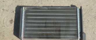
Cooling fan fuse for Lada Kalina
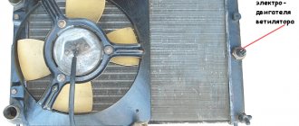
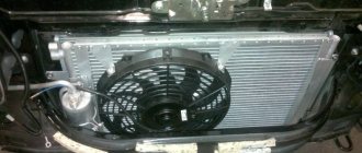
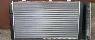
The fan is necessary for forced cooling of the antifreeze in the radiator in case of excessive engine heating. In the summer, turning on the fan is a common occurrence, and its failure can lead to boiling of the coolant .
While driving, there is a natural flow of air around the radiator. The fan is activated based on the temperature sensor readings. Thus, if the fan does not turn on, then the fault is either the sensor or the fuse.
On the Lada Kalina, the fan circuit is protected by both a fuse and a relay.
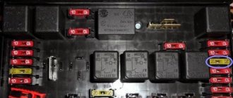
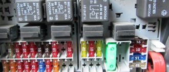
Power fuses
The power fuse box is located under the hood and is located between the battery, strut support and coolant reservoir. Looks like a vertically mounted box. By removing the top cover, access to the power fuses appears.
F1 (50 A) - electric power steering . If the steering wheel turns hard, also check fuse F32.
F2 (30 A) - heater fan
F3 (60 A) - generator . If the battery discharges quickly or the discharge lamp is on, check this fuse, as well as the operation of the generator itself and its brush.
F4 (60 A) - generator
F5 (30 A) - low beam headlights . Also check relay K9 and fuses F12, F13.
When troubleshooting any electrical problems, use caution. Replace fuses and relays only with the engine off and the ignition off.
If your fleet contains not only Grants, you can also read about Kalina fuses and relays.
Most electrical circuits in modern cars are protected by fuses. Firstly, this protects the electrical device itself from damage, and secondly, it prevents the threat of fire due to overheating or short circuit.
Where to find the cooling fan fuse
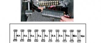
The fuse is located in an additional mounting block in the passenger compartment. The place is not very convenient. We specifically took out the block and took a photo.
It is located to the right of the instrument panel, near the air duct. To open you need:
- Unscrew the corner screw from the decorative (protective) trim, then open the cover and put it aside.
The self-tapping screw is marked with a circle.
The main difficulty is that you need to protect the wiring and carefully remove the block.
One fan relay in the diagram.
Cooling fan fuse diagram.
Articles
If after inspecting and replacing the fuse the problem is not solved, you will probably have to change the relay or the fan itself by purchasing an electric motor with an impeller. Before choosing, be sure to find out the original number, which happens:
- 1118-1308008;
- 1118-1300025;
- 21230-1300025-00;
- 2123-1300025 (for 2 motors).
There are analogues of no worse quality, but from other manufacturers.
Connection diagram
Knowing the electrical diagram for turning on the radiator fan, it will be easier to find problems in its electrical circuit.
The cooling fan has 2 inputs: the first input leads to the generator through fuse F5 and the connection busbars in the mounting block (2). The harness block (3), nicknamed the chip by drivers, connects the electric fan via a relay to the injection controller connected to the ignition relay. From the wire coming from the controller, a branch leads to an auxiliary relay with a fuse.
Where is the radiator cooling fan relay located on Lada Kalina?
Car : Lada Kalina. Asks : Abramov Sergey. The essence of the question : the radiator cooling fan is not working, the fault is with the fan relay, where is it?
Hello, my radiator cooling fan has stopped turning on. I think the relay has failed, but I don't know exactly where it is located. Please tell me!
Or maybe it's not the fan relay?
In order to accurately determine the cause of such a malfunction, it is necessary first of all to check all fan contacts for the presence of oxides and traces of rust, as well as the wiring for breaks and abrasions.
Fan relay and fuse, where are they?
The additional fuse box is marked with an arrow in the photo.
If these manipulations did not bring any success, then it is necessary to look at the fuse and relay responsible for the operation of the cooling fan.
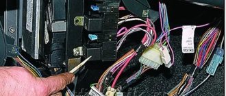
- Finding them is not difficult; you just need to unscrew one bolt located on the side of the center console near the left foot of the front passenger.
- When the decorative trim is dismantled, we will need a “10” key to remove the fuse box from its place of fixation and bring it out.
- This work may cause some inconvenience, because thick wire harnesses are connected to the relay block.
- This is how it looks after removal, now all that remains is to check their functionality and put everything back in the reverse order.
When they are dismantled from their place, you can easily carry out work on them.
- Low speed cooling fan relay.
- Main relay.
- High speed cooling fan relay.
- 50 Amp fuse.
- Relay for turning on the pump (fuel).
Source
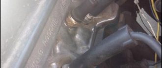
How to check the fan switch sensor
The need to check the sensor arises after the engine overheats or there is a suspicion of poor performance of the cooling system. First of all, it is necessary to check not the sensor, but the wires and relays that turn on the fan. To do this, remove the wires suitable for the sensor and short-circuit them; if there are not two, but three wires, then you need to short-circuit the middle one and each of the outer ones one by one. The fan should turn on at low and high speed, depending on which contacts are closed. If the fan turns on, it means that the wires and relays are working properly and you can start checking the sensor; if not, you need to find and eliminate the malfunction (broken wires, poor contact, blown fuse, burnt out relays or fan motor).
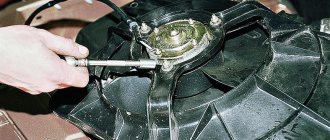
After making sure that the relay, motor and wires are working properly, proceed to checking the sensor. To do this, you will need a basin for coolant, a 30 key, a thermometer up to 100 degrees, a pan of water, a stove and a multimeter. Remove the terminal from the battery and place a basin under the car so that the coolant from the radiator does not pour onto the ground, but into it. Wait until the radiator cools down to 45 - 50 degrees, then unscrew the drain plug (it is located at the bottom of the radiator on the left or right side). After the liquid has drained, screw the plug into place. Remove the wires from the sensor (if there are 3 of them, then mark each one so that when installing a new sensor you do not mix them up), then unscrew the sensor with a 30 mm wrench.
Pour water into a saucepan so that it covers the working part of the sensor (up to the nut) and place it on the stove. Monitor the water temperature with a thermometer.
Use a multimeter to check the sensor contacts are triggered. For a three-pin one, it is advisable to use two multimeters. Turn the multimeter into resistance measurement mode with a sound signal and connect it to the sensor terminals. When the bimetallic strip closes the contacts, the multimeter will start beeping. Turn off the stove and wait until the multimeters turn off. Compare the thermometer readings at the moment the sensor contacts activate and turn off. If the deviation from the values written on the sensor body is more than 5%, it is advisable to replace it. If the deviation is more than 10%, or the sensor does not work at all, it must be replaced. Installation proceeds in the following order - screwing in the sensor, filling in coolant, connecting the battery.
Lada Kalina - fuse and relay blocks
Lada Kalina 1
The first generation was produced in 2004, 2005, 2006, 2007, 2008, 2009, 2010, 2011, 2012 and 2013 under the internal serial numbers
VAZ-1117, VAZ-1118, VAZ-1119
with sedan, hatchback, and station wagon bodies. In this article we will show a description of fuses and relays of the 1st generation Lada Kalina with block diagrams and photographs. Note the fuse responsible for the cigarette lighter.
The design of the blocks and the purpose of the elements in them may differ from those presented and depend on the year of manufacture and level of equipment of your Lada Kalina. Check the description with yours, printed on the back of the protective cover, or other technical documentation.
Main block
The main block with fuses and relays is located under the instrument panel on the driver's side, behind the protective cover.
Scheme Option 1
Scheme Option 2
Description of fuses
p, blockquote 10,0,0,0,0 —>
| F1 | 15A Electronic engine control unit, cooling fan relay, fuel injectors |
| F2 | 30A Electric windows |
| F3 | 15A Hazard alarm |
| F4 | 20A Windshield wiper, airbag |
| F5 | 25A Heater (viburnum heater fuse), Electric power steering control unit, Windshield washer |
| F6 | 20A Horn |
| F7 | 10A LCD instrument cluster indicator, Brake light switch and lamps, Interior lighting |
| F8 | 20A Heated rear window |
| F9 | 5A Side light bulbs on the right side, Glove box light bulb |
| F10 | 5A Side light bulbs on the left side, Outside lighting indicator in the instrument cluster, License plate light bulbs |
| F11 | 7.55A Rear fog light, Immobilizer control unit |
| F12 | 7.5A Low beam lamp right block - headlights |
| F13 | 7.5A Low beam lamp left block - headlights |
| F14 | 10A High beam lamp right block - headlights |
| F15 | 10A High beam lamp left block - headlights |
| F16 | 10A Right fog lamp |
| F17 | 10A Left fog lamp |
| F18 | 20A Heated front seats, cigarette lighter |
| F19 | 10A ABS |
| F20 | 15A Cigarette lighter , luggage compartment lock, diagnostic connector |
| F21 | 10A Transmission reverse lock circuit |
| F22 | 15A Security alarm control unit |
| F23 | 10A Electric power steering control unit |
| F24 | 7.5A Air conditioner |
| F25 | 10A Interior lighting, brake lights |
| F26 | 25A ABS |
| F27 | Spare |
| F28 | Spare |
| F29 | Spare |
| F30 | Spare |
| F31 | 50A Electric power steering |
| F32 | 30A ABS |
Fuse number 20 at 15A is responsible for the cigarette lighter.
Relay purpose
p, blockquote 12,1,0,0,0 —>
| K1 | Headlight washer relay |
| K2 | Power window relay |
| K3 | Additional starter relay |
| K4 | Ignition switch unloading relay |
| K5 | Alarm relay |
| K6 | Heated Seat Relay / Wiper Relay |
| K7 | High beam relay |
| K8 | Horn relay |
| K9 | Fog light relay |
| K10 | Relay for heated rear window and exterior mirrors |
| K11 | Seat heating relay |
| K12 | Fuel pump relay |
| K13 | Reverse light relay |
| K14 | Radiator cooling fan relay |
| K15 | Heated windshield relay |
| K16 | Heated windshield relay |
| K17 | A/C compressor clutch relay |
Engine control unit
This unit is located in the center console.
The fuses responsible for engine operation are located on top under the protective cover.
Photo - diagram
Designation
p, blockquote 17,0,0,0,0 —>
- Diagnostic connector
- 15A - Main relay circuits (winding of the cooling system electric fan relay, canister purge valve, air flow sensor, speed sensor, oxygen concentration sensor, ignition coil)
- 15A - Fuel pump, viburnum fuel pump fuse.
- 15A - Constant power supply circuits of the controller (ECU)
The relays are located in the lower right part of the console, where the fuses for the electric cooling fan are also attached.
The diagrams do not fit or you own a different generation of the model, study this description for the Lada Kalina 2.
We have also prepared video material on this material on our channel. Come in and subscribe.
p, blockquote 24,0,0,0,0 —> p, blockquote 25,0,0,0,1 —>
And if you have any questions, write them in the comments.
Source
Fan switch sensor
Refusal of constant rotation of the fan using a belt drive made it possible to reduce the engine warm-up time. The electric drive, which consists of a motor, relay, switching sensor and battery, allows the fan to turn on only when the engine temperature exceeds the optimal value. Thanks to this approach, the cooling system of internal combustion engines has become more efficient. Periodically turning on the fan made it possible to reduce fuel consumption, because the engine warm-up time was reduced and power losses due to the constant rotation of the blades disappeared.
Differences in electronics of Lada Kalina 1 from Kalina 2
These two cars, despite their external similarities and common base, have different electrical wiring structures.
The second generation used Renault's developments, which explains the appearance of a body electronics unit, like on the Lada Vesta. In addition, these cars received completely different mounting blocks and their location.
The difference in the mounting blocks is also explained by the appearance on the Lada Kalina 2 of an automatic transmission, climate control and heated windshield. In addition, almost all trim levels now have DRLs. Therefore, diagnosing faults related to blown fuses on these machines is carried out differently.
Where are the fuses and relays located?
Depending on the generation of the car, the fuse blocks have differences, and, consequently, different installation locations.
Location of fuse and relay blocks on Lada Kalina 1
The first generation Kalinas were equipped with several fuse blocks at once. Their location has several places and they are all in the cabin:
- The main unit is located under the panel, to the left of the steering column.
- Another block was mounted under the cigarette lighter, next to the gearshift lever.
- Another mounting block is located under the dashboard, inside the central tunnel.
Where are the mounting blocks located in Lada Kalina 2
The second generation Lada Kalina has two fuse blocks. The main one is located inside the cabin, and in some trim levels it is also installed under the hood.
- One is located in the cabin, to the left of the steering column, under the cover.
- The additional fuse box is located in the engine compartment, to the right of the battery.
It is worth considering the location of the mounting block to avoid mistakes in diagnosing the car.
Relay VAZ 2106
- Voltage regulator, which is responsible for proper charging of the battery. Located on the left mudguard.
- The wiper relay is located on the left side, under the instrument panel.
The video below clearly shows where which relay is located.
Correct selection and replacement of fuses on Kalina
The fuse in a car is a plastic product with two contacts, inside of which there is a fuse link.
Different fuses are designed for different current values and if this parameter is exceeded, the insert burns out. It is very important to install the same one in place of the required fuse and not make a mistake.
For example, if a 15 Ampere fuse is installed on the cigarette lighter, then it is no longer possible to install a 60 Ampere or 5 Ampere insert.
The fact is that with a high operating current, the device can burn out or melt the wiring in the event of a malfunction. And with a high current of 15 Amps, a 5 Ampere fuse may blow immediately after turning on the device, since it is not designed for such work.
Fuse links differ in color and amperage. Currently, the following colors and fuses are used in cars:
| Color | Clearly | Operating current |
| Brown-yellow | 5A | |
| Brown | 7.5A | |
| Red | 10A | |
| Blue | 15A | |
| Yellow | 20A | |
| White | 25A | |
| Green | 30A | |
| Orange | 40A | |
| Red | 50A | |
| Blue | 60A |
Lada Kalina cars of the 1st and 2nd generations use blade fuses of the Norma and Maxi standards. The latter are used on Kalina 2 in the engine compartment and several of them are used on Lada Kalina 1 in the cabin.
To replace fuses, there is a special puller in the main unit, which is located in the lower right corner.
Removal and replacement process
There is nothing difficult in the process of changing power supply parts, so we will not describe this process. But we will tell you how to replace an old-style power supply with a new-style device.
- First of all, disconnect the battery. Now open the driver's door and use a screwdriver to pry out the two fasteners securing the decorative interior trim. Move it to the side and you will see a block. Using a Phillips screwdriver, unscrew the screws securing the power supply. Do this carefully so that the wires do not fly off the terminals in the process.
- Once the power supply is unscrewed, move it down. But do not pull it too hard to avoid breaking the wires. Note! Jumpers must be installed on those wires through which voltage comes from the engine compartment. Do not connect the jumper after the fuse itself, otherwise this will result in voltage passing through one part to power several electrical components.
- The order of installation of jumpers should be as follows: 3-4, 5-6, 7-8, 9-10, 11-12, 12-13.
- Now you need to remove each wire one by one, starting with the first fuse from the old power supply, and mount it on the new one. Perform this operation with each contact, until the very last wire. When all the contacts are in place, you should check whether you did everything correctly. In particular, you need to turn on the voltage source and remove the corresponding fuse. If the device stops functioning, then all actions were performed correctly. For example, turn on the low beam headlights and remove one of the power supply elements responsible for the left or right headlight. If it goes out, then you did everything right.
- Check each fuse in the same way. If, when dismantling the element, the device continues to work, then the jumper is most likely installed incorrectly, so double-check the connection diagram.
This completes the replacement of the power supply with a new type device. As you can see, there is nothing difficult about this, but if you are not sure that you will do everything correctly or cannot distinguish the blue wire from the red or green, then entrust this matter to an electrician.
Sources
- https://granta-service.ru/diagnostika/predohraniteli-vaz-2106-kakoj-i-za-chto-otvechaet.html
- https://vsepredohraniteli.ru/lada/vaz-2106.html
- https://knigaproavto.ru/shemy/vaz/21032106/496-predohraniteli-vaz-2106.html
- https://rus-avtomir.ru/predohraniteli/rele-vaz-2106
- https://saturn-lada.ru/novosti/raspinovka-predohranitelej-vaz-2106.html
- https://bumper.guru/klassicheskie-modeli-vaz/elektrooborudovanie/predohraniteli-vaz-2106.html
- https://VazNeTaz.ru/publ/remont_vaz_samomu/predoxraniteli-vaz-2106-sxemy-kakoj-za-chto-otvechaet.html
How to select and replace a relay on Kalina
A relay in a car is used to remotely control consumers that require high currents.
For example, to activate the starter, the ignition switch contacts and its wiring will not be enough. Therefore, the lock serves only as a control device, and the relay closes the power contacts and the retractor relay circuit.
In cars of both generations, the most common 4 and 5-pin relays are used. However, two types of sizes are used here; this should be taken into account when selecting. It is better to look at the characteristics of the relay on the body and buy exactly the same one or show the required relay to an auto parts dealer. Automotive relays can vary in current strength, number and location of contacts.
To replace faulty relays and fuses on the Lada Kalina, use a special “pliers” tool, which is installed in the lower right corner. The larger ones are for relays, and the smaller ones are for fuses.
If, after replacing the fuse, it has blown again, you should not try to change it again; most likely there is a short circuit in the circuit and the car must be sent for more thorough diagnostics.
Fuse and relay diagram in Kalina 1
As mentioned earlier, in the first generation Lada Kalina there are three fuse and relay blocks. Therefore, each should be considered separately.
Main unit
To understand which fuses are installed in the main unit and what they are responsible for, you should read the table:
| Number | Operation current, A | What is he responsible for? |
| F1 | 10 | Hazard alarm, direction indicators, anti-theft system (immobilizer), instrument panel |
| F2 | 30 | Power windows |
| F3 | 10 | Alarm |
| F4 | 20 | Washer and wiper |
| F5 | 25 | Electric power steering ECU and heater motor |
| F6 | 20 | Horn |
| F7 | 10 | Interior lamps, instrument panel |
| F8 | 20 | Rear window defroster heating element |
| F9 | 5 | Dimensions - right side of the vehicle |
| F10 | 5 | Dimensions – left side of the vehicle |
| F11 | 7,5 | Immobilizer control unit |
| F12 | 7,5 | Low beam - right headlight |
| F13 | 7,5 | Low beam - left headlight |
| F14 | 10 | High beam - right headlight |
| F15 | 10 | High beam - left block headlight |
| F16 | 10 | PTF - right side |
| F17 | 10 | PTF – left side |
| F18 | 15 | Seat heating |
| F19 | 10 | Anti-lock braking system ECU |
| F20 | 15 | Cigarette lighter |
| F21 | 10 | Reverse switch |
| F22 | 15 | Standard alarm control unit |
| F23 | 25 | EUR |
| F24 | 7,5 | Email Air Conditioner Magnetic Clutch |
| F25 | 30 | Power supply |
| F26 | 25 | Anti-lock braking system ECU |
| F27 | 50 | EUR |
| F28 | 40 | ABS |
The last four fuses are backup and are necessary to replace blown ones.
To find out which relay is responsible for what in Lada Kalina 1, just study the following table:
| Number | Designation |
| K1 | Headlight wiper |
| K2 | Power windows |
| K3 | Starter |
| K4 | Additional relay |
| K5 | Relay-breaker for direction indicators and hazard warning lights |
| K6 | Windshield wiper and washer |
| K7 | High beam |
| K8 | Horn |
| K9 | PTF |
| K10 | Heated rear window |
| K11 | Seat heating element |
| K12 | A/C compressor clutch |
Fuse box under the cigarette lighter
There are only three inserts installed here. The purpose of the fuses is to protect the circuits of the engine injection system.
| Number | Current | Designation |
| F1 | 15A | Main relay switching circuit |
| F2 | 15A | Gasoline pump |
| F3 | 15A | Constant “+” power supply to the ECU |
Fuse and relay box under console
Closes the power parts of the engine injection system. On the second generation of the car, almost all relays and fuses from here will go to the main mounting block.
| 1 | Low fan speed |
| 2 | Main relay |
| 3 | High fan speed |
| 4 | Fuel pump relay |
| 5 | Electric fan fuse |
| 6 | — |
"Euroblock" VAZ 2106 (new model), diagram
Below is a picture of what the Eurobloc looks like in real life.
Replacing the VAZ 2106 fuse box with a “Euroblock”
And finally, for those who don’t know how to replace the old model with a “Euroblock”, the following information. There is nothing complicated here.
You just need to follow the instructions below:
- First you need to disconnect the minus from the battery.
- Use a 10mm wrench to unscrew the old power supply. In this case, the wires are not disconnected.
- According to the diagram above, wires and jumpers are installed.
- It is important to install jumpers only on those wires that carry voltage from the engine compartment.
- Jumpers are installed between pins 3-4, 5-6, 7-8, 9-10, 11-12.
- Next, the wires are removed one by one from the old device and attached to the Euroblock.
- At the end, check that the connection is correct (for example, with the low beam on, if you pull out the 5th fuse, the left headlight should go out).
- All other circuits are also checked.
The video below clearly shows how to replace an old power supply with a Euroblock.
Table of fuses and relays in Lada Kalina 2
Lada Kalina 2 is significantly different from its predecessor and has a slightly different block with a different arrangement of fuses.
Main unit in the cabin
To understand what the relays and fuses on Kalina 2 are responsible for, study the table:
| Number | Operation current, A | Protected circuit |
| F1 | 15 | Power supply to engine ECU, ignition coils, fuel injectors and electric fan |
| F2 | 25 | UCH |
| F3 | 15 | ECU and automatic transmission drive |
| F4 | 15 | SRS ECU |
| F5 | 7,5 | Engine ECU, instrument cluster, UCH, power steering, brake light, speed sensor, automatic transmission mode selector, heated window switch and relay and heated seats |
| F6 | 7,5 | Reverse signal, automatic transmission controller, standard parking sensors and turn indicators |
| F7 | 7,5 | Canister valve, power supply for camshaft sensor, oxygen sensor, mass air flow sensor and manifold absolute pressure sensor |
| F8 | 25 | Heated mirrors and rear window |
| F9 | 5 | Side lights on starboard side |
| F10 | 5 | Side lights on the left side, instrument panel and key lights, license plate lights, glove box lights |
| F11 | 5 | Rear PTF |
| F12 | 10 | Low beam and headlight range control (right headlight) |
| F13 | 10 | Low beam and headlight range control (left headlight unit) |
| F14 | 10 | High beam - right side |
| F15 | 10 | High beam - left side |
| F16 | 10 | PTF front right |
| F17 | 10 | PTF front left |
| F18 | 15, 20 or 10 | Cigarette lighter and heated front seats |
| F19 | 20, 7.5 or 5 | Central locking control unit and ABS unit power supply |
| F20 | 15 | Horn |
| F21 | 10 | Gasoline pump |
| F22 | 15 | Front windows, windshield washers and rear wipers |
| F23 | 5 | Power supply for instrument panel and diagnostic connector |
| F24 | 7,5 | Compressor clutch and climate control unit power supply |
| F25 | 7,5 | Interior lamp, brake light |
| F26 | 25 or 10 | Anti-lock braking system or UCH valves |
| F27 | 25 or 30 | ABS valves or heater motor |
| F28 | 30 | Heater motor or climate control power supply |
| F29 | Reserve | Reserve |
| F30 | Reserve | Reserve |
| F31 | 30 | Momentary activation of high beams, front door power windows or ABS valves |
| F32 | 30 | Heater and climate control |
Relay designations in Kalina 2
| Relay number | Designation |
| K1 | Electric cooling fan |
| K2 | Window lifters |
| K3 | Starter control |
| K4 | Ignition Load Relay |
| K5 | Hazard warning and direction indicators |
| K6 | Windshield wipers or heated front seats |
| K7 | High beam |
| K8 | Sound signal |
| K9 | Low beam |
| K10 | Heated mirrors and rear window |
| K11 | Engine ECU ON Relay |
| K12 | Gasoline pump |
| K13 | Hazard or reverse lights |
| K14 | Additional relay for emergency lights or cooling fan |
| K15 | Heated windshield (two sections) |
| K16 | Heated windshield (two sections) |
| K17 | Air conditioning compressor |
Fuses under the hood of Kalina 2
Check out the engine compartment fuse table:
| F1 | Heated glass or generator |
| F2 | Generator |
| F3 | Generator or cooling fans |
| F4 | Cooling fan or ESP controller |
| F5 | Power steering or ESP unit power supply |
| F6 | Power supply for EUR or ABS pump |
Depending on the year of manufacture, different vehicle configurations may have different fuse designations.
In general, miracles began to happen to me.
Hi all. I discovered a few days ago, when I opened the hood, that the cooling fans were jerky. Those. It does not work evenly, on/off and at different speeds. It doesn’t matter whether the engine is hot or cold. I turn off the engine, the fans run for another 10 seconds, then turn off. That's how it should be. The condenser is on - everything works smoothly and well. Off - miracles begin again. Tell me, what's going on? What to watch. The car is not heating up yet, but I’m afraid that this whole system will not work for long in this mode.
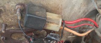
The signal from the temperature sensor goes to the fan control module, then through a relay to the motor. I would start digging with the relay. IMHO.
The relevant fuses under the hood are No. 41 (well, this is a common 100A), then No. 42 (40A, but this is also common to a bunch of everything), No. 57 (20A - this is the main one for the engine cooling fan), and fuse under the steering wheel No. 17 (7.5A on the fan relay). Actually, the relay itself is located in a block under the hood, called RADIATOR FAN RELAY. I would start the check something like this: if the car has air conditioning, then turn it on - both fans should spin. If there is no air conditioner, then we short-circuit the temperature sensor responsible for the fan to the housing (two similar ones, it seems to be located under the distributor and closer to the radiator, you need to find the one to which the green and black wires go, short the green one to the housing or just the wires to each other). If the propeller does not spin, listen to see if the relay clicks. If the relay clicks, but the propeller does not spin, then feel for fuse No. 57. If it is intact, the relay clicks but does not spin, then check the voltage at the fan terminals. If not, then the wiring and the relay itself (you can pull it out and check it with a jumper or install it temporarily from another socket). If voltage is supplied but does not spin, disassemble the fan and look at the brushes, etc.
Yes, by the way, the numbering of the fuses may differ - correctly noted. I take it from the service manual for the American one, but it matches my European one.
I have a problem too! the fans do not turn on. but when the air conditioner is turned on they work. All fuses are intact, how can I check the relay?
Why do fuses blow and what are the symptoms?
Fuses never blow without a reason, and the Lada Kalina is no exception. Fuse links protect circuits from the following faults:
The task of the fuse is to save the electrical circuit: wiring, consumers and to prevent a fire caused by melting of wires or other parts of the electrical circuit.
A short circuit is one of the reasons for the melting of the insert, which most often occurs due to damage to the wires, a short circuit of the “plus” to body ground, or during an accident, as a result of which the harness or a separate wire was cut by a part of the body.
Overloads can be caused by the simultaneous operation of many consumers or when using low-quality compressors to inflate tires, powered from the cigarette lighter.
There is another reason, which occurs extremely rarely - the use of Chinese fuse-links, the operating current of which is slightly lower than that provided by the electrical circuit. Despite the fact that 15A may be indicated on the insert body, in fact, this figure may be lowered to 10.
The symptom of a blown fuse is complete failure of the consumer. For example, if the cigarette lighter does not work, then in 90% of cases, a blown fuse is to blame. To make sure of this, just open the lid, take out the fuse-link, guided by the table, and check its integrity. If this cannot be done visually, you can use a multimeter in dial mode.
A serviceable fuse should ring, but a blown fuse will show an open circuit on the device. If replacing the insert does not help, you will have to diagnose the fuse box or look for the problem elsewhere.
It is prohibited to use wire to repair the fuse! This may cause the wiring in the vehicle to catch fire.