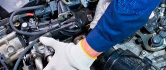
Let's analyze the design and principle of operation of the forced idle economizer (EFS) of carburetors of the Solex family installed on the engines of VAZ 2108, 2109, 21099 cars and their modifications.
EPHH is one of the carburetor systems 2108, 21081, 21083 Solex. It is responsible for ensuring that the car engine operates at forced idle. The forced idle economizer system of the Solex carburetor 2108, 21081, 21083 is designed to cut off the fuel supply through the idle system during engine braking and after turning off the ignition. It provides a reduction in fuel consumption to 0.5 liters per 100 km, prevents the occurrence of diesel ignition (glow ignition), and reduces the emission into the atmosphere of toxic compounds formed when mixture formation deteriorates in the ISF mode.
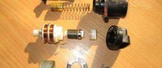
EPHH Solex device
The carburetor solenoid valve is an actuator of the system that, at the command of the control unit, closes with its needle the hole in the fuel nozzle of the XX system, thereby stopping the fuel supply through it. Installed in the carburetor.
Control unit – the electronic control unit is the control element of the EPHH. It reads the frequency of pulses in the ignition system (via terminal “K” of the ignition coil) and uses them to determine the engine crankshaft speed. In addition, the control unit receives a signal from the contact of the fuel mixture “amount” screw to close or open the throttle valve of the first chamber. At a certain shaft speed and an open throttle signal, it turns off the voltage supply to the solenoid valve, which shuts off the fuel supply through the CXX. The unit is installed on the engine compartment panel next to the ignition system switch.
Contact of the fuel mixture “quantity” screw (sensor-screw) – the tip of the fuel mixture “quantity” screw with the wire attached to it. When the gas pedal is released and the throttle valves are closed, the contact touches the edge of the lever on the throttle valve axis (closed to ground), and a signal is sent to the control unit that the throttle valve is closed.
After pressing the gas pedal, the contact between the tip of the quantity screw and the throttle lever opens (not shorted to ground), and a signal is sent to the control unit that the throttle valve is open. Installed on the carburetor.
visible elements of the EPH system of a Solex carburetor in the engine compartment of a VAZ 21083 car
Operating principle of the forced idle economizer system of a Solex carburetor
The movement of a car by inertia with the gear engaged and the gas pedal released (engine braking) is called forced idling (FID). In this mode, the combustion conditions of the fuel mixture in the engine cylinders sharply worsen, CO and CH emissions increase, and fuel consumption increases. EPHH shuts off the fuel supply in IHH mode to the engine cylinders, thereby optimizing the composition of the fuel mixture and saving fuel.
In this situation, the control unit receives signals from the ground-closed contact on the “quantity” screw that the throttle valve is closed and from the coil about the current crankshaft rotation speed. If the rotation speed is above 2100 rpm, it stops supplying voltage to the output of the carburetor solenoid valve and it will close the opening of the CXX fuel jet. The fuel supply through the idle system will stop. As soon as the crankshaft speed drops to 1900 rpm, the control unit will resume supplying voltage to the solenoid valve. Its needle will retract and open a hole in the CXX fuel jet. The idle system will work.
That is, to forcibly shut off the fuel supply through the idle system, the electronic control unit requires two conditions - a signal about the closed throttle valve and a signal about the engine speed.
Malfunctions in engine operation associated with Solex EPH
— The engine stalls while the car is moving when the gas is released
A similar malfunction can occur if the carburetor idle system is clogged. This must be taken into account when diagnosing EPC faults.
— Dieseling (glow ignition)
The engine runs for some time after the ignition is turned off.
Notes and additions
Forced idle speed (FID) is one of the engine operating modes. Performed while the vehicle is moving with the gear engaged and the gas pedal fully released. For example, when braking with the engine or driving downhill. In this case, the throttle valves of both chambers of the carburetor are completely closed, the engine crankshaft speed is above 1900 rpm. Below 1900 rpm the idle system comes into operation.
Dieseling (glow ignition) - short-term engine operation after turning off the ignition. The fuel entering the engine cylinders under the influence of vacuum from the carburetor is ignited by a heated spark plug, flashes occur in the combustion chambers, moving the pistons. Possible when the EPH system is faulty and “hot” spark plugs are used (plugs with temperature characteristics that do not correspond to this type of engine).
More articles on Solex carburetors
The forced idling economizer or EFHS can significantly reduce the emission of toxic substances into the atmosphere. It also reduces fuel consumption.
What is an economizer?
Design and connection diagram of the economizer
The EPHH device is not particularly complicated, despite this, the effectiveness of the system is beyond doubt. The standard design consists of the following elements:
- ignition coil,
- insulated tip,
- screw,
- solenoid valve,
- EPHH control unit.
Each of these parts interacts with each other. The result of this process is increased engine performance and a significant increase in fuel economy. But in order to achieve such a result, everything must be connected correctly. You can find out how to do this from the EPHH connection diagram below.
Instrument panels VAZ-2107: diagram, description
The VAZ 2107 car is equipped with a dashboard, which is necessary for the driver to monitor traffic conditions and notice malfunctions in time. When driving a car, the driver is obliged to monitor not only the road surface, but also the condition of the main parts of his vehicle. These main parts include:
- movement speed;
- engine temperature;
- presence of fuel in the tank;
- amount of oil in the engine.
And these are just the main points that the driver monitors while the car is moving. This article will tell you about the main elements of the instrument panel, which will be discussed in the diagram below.
Results
EPHH allows you to achieve significant fuel savings. This is an extremely advantageous design solution that allows you to increase engine performance at minimal cost. A separate bonus is the reduction in exhaust gas toxicity.
To control the EPHH valve in carburetor engines of VAZ 2108 - 2110 cars, the EPHH control unit
50.3761. A screw sensor is used as a throttle position sensor, which is a plastic screw with a metal tip that is screwed into a bracket fixed to the carburetor.
When the throttle valve is opened, the tip of the screw, with the wire attached to it, does not rest against the throttle valve lever. This leads to a break in the circuit of output 5 of the control unit with ground. In this case, transistor VT7 closes, and transistor VT5 opens, in turn opening transistor VT8. Transistor VT8 supplies power to the solenoid valve regardless of the crankshaft speed.
A wire connects to pin 3 of the control unit, connecting it to the pin of the primary ignition coil, transmitting pulses that go to pin 4 of microcircuit A1. At pin 3 of the microcircuit, pulses of constant duration are formed, the repetition of which corresponds to pulses from the distributor. Transistors VT1 and VT2 discharge timing capacitor C1. If the crankshaft rotation speed is less than 1100 rpm, then the voltage on the capacitor does not rise; as the speed increases, the voltage increases and when it exceeds 8 V, transistors VT3 and VT4 open, which through microcircuit A2 open transistor VT6 and, accordingly, VT8.
Device diagnostics
Motorists are interested in how to check the idle air valve themselves and its current condition.
For many car enthusiasts, independently checking this valve, a component of the idle air system, is a completely doable task. There are several methods for diagnosing the condition of the regulator.
- Visual inspection. First a visual inspection is carried out. This allows you to determine the presence of defects on the body, signs of needle wear, and signs of carbon deposits on surfaces. If there are deposits, they can be removed using carburetor cleaner. Surely, if the IAC is dirty, the entire throttle assembly will be dirty. Therefore, it will not be superfluous to clean it too.
- Diagnostic software. Some car enthusiasts are switching to using special diagnostic programs. In addition to the software, an adapter is also required to connect to the system. Through the software menu, the position of the controller is selected and its operation is observed.
- Wiring condition. It would not be superfluous to carefully check the wiring connected to the IAC. Here you need to use a multimeter. The engine is turned off, the sensor connector is removed. On the multimeter, select the voltage test mode with a limit from 0 to 20 V. When working properly, the device should show about 12 V.
- Resistance. The resistance of this regulator is also checked. To do this, using the same multimeter, the resistance between the terminals is checked by disconnecting the sensor terminals. The multimeter is turned on in resistance mode, and the limits are set from 0 to 200 Ohms. The terminals are conventionally designated as A, B, C and D. When measuring resistance at A and C, as well as at B and C, the device should display infinity. In other cases, 50-55 Ohms is considered the norm.
- Check with throttle. Checking with the throttle assembly is also quite common among motorists. The complexity of the method is that you will have to completely dismantle the entire throttle assembly directly along with the sensor itself. After connecting the IAC connector, turning the ignition on and off, visually observe the operation of the suspected regulator. Make sure that the needle moves normally, the stroke is uniform, and there are no extraneous sounds.
In most cases, when the IAC fails, it is replaced with a similar part.
What does the EPCH system consist of?
The EPHH system includes a control unit, an electromagnetic valve or an electromagnetic pneumatic valve, and a throttle position sensor. A distributor breaker is often used as a speed sensor.
The throttle position sensor can be a microswitch, the contacts of which open when the throttle valve is closed, or a sensor-screw at the end of which a wire is attached connecting the terminal of the control unit to ground when the throttle valve is open.
The speed sensor in a carburetor engine is the distributor breaker.
The fuel supply is stopped by a solenoid valve or an electro-pneumatic valve, depending on the design of the carburetor. The solenoid valve is installed on the carburetor and, in the absence of power to it, closes the idle channel with its core. An electro-pneumatic valve is installed on the car body at the break in the tube connecting the intake manifold to the economizer module; when turned on, it disconnects the economizer from the manifold and connects it to the atmosphere. As a result, the economizer valve stops the fuel supply.
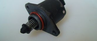
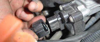
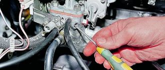
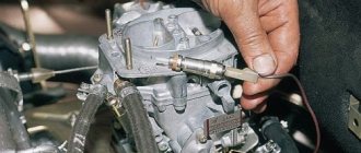
Removing and checking the solenoid valve
Remove the air filter housing (see Removing the air filter housing)
Remove the wire from the solenoid valve.
Using the “13” key, unscrew the solenoid valve
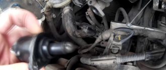
...and take it out along with the idle jet and the rubber sealing ring in the cup.
If necessary, remove the O-ring and cup.
We take out the jet.
We check the serviceability of the solenoid valve and its circuit.
To do this, we put the removed wire on the valve terminal and, turning on the ignition, press the valve body to the carburetor - the needle should click into the valve, and when the voltage is removed (we remove it from the body), it should return to its original position without jamming.
To check the serviceability of the valve itself, we connect its terminal with a wire to the “plus” of the battery, and the body to the “minus”.
If the needle does not retract, the valve is faulty
Install in reverse order.
The valve should not be over-tightened (it must be tightened by hand; if it is over-tightened, the valve will not work).
The need for an EPH system.
Driving a car using forced idle occurs extremely rarely, mainly in mountainous areas. Therefore, even the promised 2-3% is practically an unattainable goal. But preventing engine detonation is very often necessary. But to implement detonation prevention when the ignition is turned off, it is not necessary to connect the entire circuit. To do this, simply apply power to the valve when you turn on the ignition and remove it when you turn it off.
The forced idling economizer or EFHS can significantly reduce the emission of toxic substances into the atmosphere. It also reduces fuel consumption.
Varieties based on material of manufacture
Mainly cast iron and steel structures are used. Cast iron is good because it has a strong, wear-resistant structure that can withstand water hammer and mechanical stress. But a high-temperature economizer cannot be used in such a housing. What it is? These are models of heat exchangers that provide not just preheating, but also bringing water to high temperatures. Cast iron under such conditions can burst without the possibility of recovery.
Read more: Windshield wipers stop in the field
Steel models are formed by pipes with diameters on average from 30 to 40 mm. They are installed in a checkerboard pattern on a single frame, which gives the entire structure strength. In practice, a heating boiler with an integrated steel economizer can withstand elevated temperatures and considerable pressure. The only drawback of steel is its susceptibility to corrosion. Therefore, special expensive grades of alloys are used for economizers.
What is an economizer?
Design and connection diagram of the economizer
The EPHH device is not particularly complicated, despite this, the effectiveness of the system is beyond doubt. The standard design consists of the following elements:
- ignition coil,
- insulated tip,
- screw,
- solenoid valve,
- EPHH control unit.
Each of these parts interacts with each other. The result of this process is increased engine performance and a significant increase in fuel economy. But in order to achieve such a result, everything must be connected correctly. You can find out how to do this from the EPHH connection diagram below.
Principle of operation
There is such a thing as engine braking. Simply put, this is a situation where the car continues to move due to inertia. In this case, the gear is still engaged, and the pedal responsible for the carburetor is released. This condition is also called forced idle. Hence, in fact, the abbreviation.
At the same time, very interesting and important processes occur inside the engine. Naturally, the fuel mixture in the cylinders continues to ignite. But at the same time, the efficiency of the system drops several times. As a result, exhaust gases have an increased content of carbon monoxide and hydrocarbons.
Attention! At forced idle, fuel is consumed extremely uneconomically.
Naturally, automotive engineers could not just leave such a defect. The result of much research and experimentation was the invention of the EPCH system. It allows you to turn off the fuel supply when idling, thereby solving a number of the problems described above.
Shutting off the fuel supply is made possible thanks to an electromagnetic valve, which is mounted in the carburetor cover. In this design, the control unit is responsible for supplying current. Together with the valve, it creates one electrical circuit, which also includes:
- power supply;
- a sensor that fixes the throttle position;
- ignition coil,
- weight.
Information is transmitted via an electrical impulse that comes from the ignition coil. It usually contains speed data. The sensor signals that the carburetor has entered idle mode. This is the third pin that connects to one of the screws. The short circuit is made to ground.
The EPHH system operates in such a way that at idle the winding of the fifth solenoid valve is de-energized. The result of this action is to stop the fuel supply.
In order for the fuel supply to resume, the EPH system using the second unit must register two changes:
- The crankshaft rotation speed should exceed 2000 rpm.
- The throttle valve must be in the closed position.
Only when these two conditions are met will the EPH system be able to resume fuel supply. But it's not that simple. If no difficulties should arise in understanding the internal processes, then another logical question arises: what does the driver need to do for this?
It's actually quite simple. In order for the EPH system to resume fuel supply, the driver needs to perform some actions. First you need to reduce your speed. In this case, you must not press the pedal that controls the position of the throttle valve.
Self-adjustment of the mechanism
Due to the fact that Solex is an emulsion-type mechanism consisting of two chambers, it can be used in almost all car models. This DAAZ product is equipped with throttle valves that open one by one. This ensures the necessary reliability and high level of quality of the device. Thanks to the well-chosen cross-section of the diffusers, the DAAZ mechanism does not require additional modification.
Self-adjustment of the VAZ 2108 carburetor is carried out as follows.
There are idle jets at the ends of the Solex magnetic valves. The functionality of the nozzle channels is checked with a jet of compressed air. This is usually done this way. When the device is repaired, its top cover is removed. On the opened plane there are three channel holes. The magnetic valve with the tip for the jets is unscrewed. Next, the air compressor starts. A hose with compressed air is inserted into the opened nozzle seat. The jets of air coming out of the channels are checked by touch with your fingertips on top of the plane.
If the pressure of the air stream is not felt above any channel of the jets, then this channel must be cleaned.
Results
EPHH allows you to achieve significant fuel savings. This is an extremely advantageous design solution that allows you to increase engine performance at minimal cost. A separate bonus is the reduction in exhaust gas toxicity.
When a car is driving in a city, the engine operates at forced idle about 25% of the time, when the engine crankshaft rotates due to the kinetic energy of the car and it moves with the gear engaged and the throttle pedal released. In such modes, the engine is controlled using a forced idle economizer.
UAZ forced idle economizer control system, control unit, valve, microswitch.
At forced idle, the engine consumes fuel without performing useful work; as a result of rapid closing of the throttle valve, the fuel mixture becomes overrich and the toxicity of the exhaust gases increases. To reduce fuel consumption and exhaust gas toxicity, UAZ vehicles are equipped with an electrical control system for a forced idle economizer (EFI).
The control system and electrical equipment of the forced idle economizer on UAZ vehicles with UMZ engines includes a control unit 1422.3733, a solenoid valve 1902.3741 and a carburetor limit switch (microswitch) 421.3709.
The operating principle of the forced idle economizer control system on UAZ vehicles.
The forced idle mode is characterized by two signs: the engine crankshaft speed is higher than the idle speed and the carburetor throttle valve is closed. Information about the engine crankshaft speed is supplied to the EPHH control unit from a sensor, which uses the primary winding of the ignition coil, and information about closing the throttle valve is from a limit switch, microswitch or screw sensor.
When you release the accelerator pedal, as a result of switching the contacts of the carburetor limit switch, the EPHH control unit generates control signals for the electromagnetic (electropneumatic) fuel supply valve depending on the engine crankshaft speed. If the crankshaft speed is higher than the idle speed, the control unit removes voltage from the solenoid valve and the fuel supply to the engine is stopped.
In this case, the crankshaft rotation speed decreases, and when it becomes less than the idle speed, the control unit will connect the on-board voltage to the solenoid valve. The fuel supply will resume and the crankshaft speed will increase.
When the crankshaft rotation speed again becomes higher than the idle speed, the control unit will again turn off the solenoid valve. The process is repeated. Periodically turning off the fuel supply in this mode reduces gasoline consumption by 2-3%, and exhaust gas toxicity is reduced by 15-30%
When you press the accelerator pedal, the limit switch contacts switch in such a way that the on-board voltage is constantly supplied to the solenoid valve. In this case, fuel will be supplied regardless of the engine speed.
Control unit 1422.3733 for forced idle economizer on UAZ vehicles, operating principle.
On UAZ vehicles with UMZ engines, four-pin economizer control units 1422.3733 are used. Microswitch 421.3709 is used as a throttle position sensor. When the throttle valve is closed, voltage pulses proportional to the crankshaft rotation speed are supplied from the primary winding of ignition coil 1 to the input of a semiconductor switch assembled on transistor VT1.
During the pulse, the key opens and the capacitor SZ is discharged. In the pauses between pulses, the capacitor SZ is charged. The charging time, and therefore the voltage at the SZ, increases with decreasing crankshaft speed. At a frequency greater than the idle frequency, the voltage on the SZ is low, transistors VT2, VT4, VT5, VT6 close. No voltage is supplied to the electromagnetic (electropneumatic) valve.
The valve closes and the fuel supply stops. The crankshaft speed drops. At a frequency lower than the idle frequency, the SZ capacitor, during the pause between pulses, manages to charge to a voltage exceeding the reference voltage of the threshold element assembled on transistors VT2, VT4. At the same time, transistors VT2 and VT4 open, which ensures the opening of transistors VT5 and VT6. In this case, voltage is supplied to the electro-pneumatic valve.
The valve is activated and turns on the fuel supply. When the throttle valve is opened, the contacts of microswitch S1 close and the on-board voltage is constantly supplied to the electro-pneumatic valve. The valve is constantly open regardless of the signals from the forced idle economizer control unit 1422.3733.
How does a carburetor work?
The following figure will help you understand its operating principle.
This is the simplest version of the carburetor, one can say that it only explains its structure and the main idea. Gasoline is in the float chamber at a constant level, which is maintained by the operation of the needle valve. Through the air filter, air is drawn into the engine cylinders. It passes through the mixing chamber, thanks to the narrowing there, in this place a vacuum is created in relation to the float chamber, in which the level of atmospheric pressure is maintained.
Due to the resulting pressure difference, fuel enters the mixing chamber. Passing through the nozzle, it breaks into small droplets, evaporates and mixes with air, resulting in the formation of a fuel assembly that enters the engine cylinders. The relationship between these components depends on the position of the carburetor damper, which is associated with the position of the accelerator pedal. The harder it is pressed on the car, the more the damper is open, the higher the degree of vacuum and the more gasoline is supplied to form the mixture.