Wiring diagram of Lada Priora: full pinouts and decoding
Car designs are rich in electrical equipment and electronics. Electrical wiring for a car is as important as veins are for the human body. Experienced drivers can navigate this web of wires without any problems, but for inexperienced drivers, learning to read electrical diagrams is useful, because if a problem occurs, you can figure out where it happened and what to check before calling a car service center.
There are three main lines in the wiring of the Lada Priora electrical circuit: for supplying energy, the starting circuit and the circuit for supplying energy consumers. Each of the car's systems is connected by a harness of wires that connect instruments and electrical equipment. There are four main harnesses in the Priora electrical circuit:
- coming from the instrument panel;
- providing motor control;
- front electrical harness;
- rear electrical harness.
All these harnesses are connected to each other using detachable connections. The connectors are located under the dashboard. Each of the harnesses is assigned a serial number.
In addition to the main ones, there are secondary electrical harnesses:
- installed in the front passenger door;
- identical in both the left and right rear doors;
- installed in the driver's door;
- connecting the backlight of the license plate;
- connecting the electrical package.
Each element in the diagram corresponds to a number with an explanation. Since all elements are standardized, their designations are identical on car diagrams of all car manufacturers. Next to each electrical appliance, the connectors that go to them are indicated. The pins or sockets of the pads are also numbered. Each block has colored wires (the color of the wires in the diagram corresponds to the color of the wire in the car).
At the top, the wires are numbered with numbers written through a fraction. The first number indicates which electrical appliance it goes to. The second number indicates which connector the wire goes to. Wires in electrical wiring connected using connectors (marked with the letter C and a number), or using terminal blocks (marked with the letter S and a number).
The layout of pins, or connecting contacts to certain nodes is called pinout.
M73 Avtel ecu pinout
ECU M73
The M73 ECU appeared on the VAZ assembly line in 2008 in connection with the transition to toxicity standards. From a circuit design point of view, this block is the closest relative of the already familiar .2+.
There are 2 types of software for this ECU:
* 2 854.3763.000–02 45 7311 XXXX M7.3 E3 * 2 855.3763.000–02 45 7311 XXXX M7.3 E3 * 2 855.3763.000–02 45 7311 XXXX M7.3 E3
* 2 851.3763.000–01 45 7311 XXXX M7.3 E3 “Classic” * 2 “Kalina”
Please note that the ECU can be produced both at the AVTEL plant and at the ITELMA plant, respectively, the firmware identifiers will begin with the letter “A” or “I”:
AVTEL software can currently be found only on front-wheel drive cars, and VAZ software can be found on classics and Kalinas. These types of software have nothing in common with each other, that is, they differ fundamentally in their algorithmic model.
AVTEL projects have software related to . The fundamental difference is only in the algorithm of operation of the detonation channel (the AVTEL model is implemented, which we have known in a simplified form since the time of .1, and the M73 software implements the VAZ model, similar to the ECU /7 model). Theoretically, this software can work with DBP, and the MAF/DBP operating mode is switched by the configuration flag).
Calibrations M73 Avtel in ChipTuningPRO
The VAZ project has its own software, which is a further development of software .2. Many calibrations in this software are similar to similar calibrations of ECU .2, both in name and in algorithmic purpose.
Calibrations M73 VAZ in ChipTuningPRO
You can work with M73 if you have purchased additional modules for the bootloader and ChipTuningPRO.
Diagnosis of an ECU with VAZ software (2) is possible using the current version if you select the ECU type Bosch M7.9.7 (diagnostic protocols are identical). The AVTEL software protocol is similar to the ECU protocol. Diagnostic support for these ECUs is already implemented in . Closed ECU versions
Since the end of 2009, all new versions of the M73 ECU are “closed”, that is, protected from reading and writing the firmware in the usual ways. When you try to read such an ECU through the BootLoader of the processor, the read dump will contain “garbage” in the form of a byte sequence: 9B 00 9B 00 9B 00... When you try to read it using the diagnostic method (without opening the ECU), the bootloader will display the message “Error starting the bootloader.” Please note that in this case you cannot attempt to write firmware to the unit using the usual methods; this may lead to complete inoperability of the ECU!
Changes in hardware implementation
In 2010, new versions of the hardware implementation of the M73 ECU appeared. In order to reduce the cost, the TDA3664 chip was removed from the circuit, which provided power to the processor (and, accordingly, RAM) when the ignition was turned off. Of course, in this case, the data of all adaptations would be lost, but in the new firmware I(A)303CF06 and I(A)327RD08, before turning off the processor power, the adaptation data is written to EEPROM. When the ignition is turned on, the contents from the EEPROM are written to RAM, so the ECU behaves exactly the same as if the power had not been turned off. In order to implement this algorithm, the EEPROM 95160 (or Atmel 25160) chip must be installed in the unit, instead of the previously installed 95080. Thus, it turns out that for older firmware versions to work, the ECU must have TDA3664 and EEPROM of any size installed, and for new firmware - TDA3664 is not needed (but if installed, it will not interfere with work), and the EEPROM must be of double capacity (95160 or 25160). Take these features into account with these ECUs, otherwise the system will not be able to operate normally. It should be noted that the latest M73 blocks of the old hardware implementation already had EEPROM of double capacity, therefore, they are the most universal, you can “pour” any firmware into them.
5-3-2016 14:21 | Posted by: Mat | | Comments: 57 | Author: djokean007
The M73 ECU appeared on the VAZ assembly line in 2008 in connection with the transition to Euro-3 toxicity standards. From a circuit design point of view, this block is the closest relative of the already familiar Mikas-11 and January-7.2+
Electrical connection diagram for the ignition system of a Lada-Priora car
The spark ignition system wiring diagram section contains graphical information about the supply of current to the main automated instruments and the vehicle's electronic engine control system. From them, the voltage is distributed to the main blocks, power plants, as well as control sensors and ECUs.
| Contact no. | Decoding |
| 1 | ECU power supply |
| 2 | Connecting the ignition system harness to the dashboard harness |
| 3 | Fuse box |
| 4 | Measuring device for determining the speed of movement |
| 5 | Road roughness detection sensor (located on the shock absorber support cup) |
| 6 | Oil pressure warning light indicator |
| 7 | TPS sensor |
| 8 | DTOZh sensor |
| 9 | Coolant temperature indicator |
| 10 | MAF sensor (MAF sensor) |
| 11 | Idle air valve (IAC) |
| 12 | Main fuel pump relay |
| 13 | Power fuse for the fuel pump |
| 14 | Starter relay |
| 15 | Starter relay fuse (15A) |
| 16 | ECU fusible link |
| 17 | Crankshaft position sensor (CPS) |
| 18 | Oxygen sensor |
| 19 | Camshaft phase sensor |
| 20 | Knock Level Sensor |
| 21 | Solenoid valve for filter purge and vapor recovery |
| 22 | Lambda probe |
| 23 | Electronic ignition module power supply |
| 24 | Supplying voltage to spark plugs |
| 25 | Fuel injector power |
| 26 | Harness block from ignition coil to ECM harness |
| 27 | Harness block from the ignition system to the ignition coil wiring harness |
| 28 | Engine computer connector to injection system |
| 29 | Injection system harness block to ignition system harness |
| A | To terminal (+) AB |
| B1, B2 | Places for attaching ground wires of the ignition system |
| C1 | Place of attachment of the ground wire coming from the ignition coils |
How to find out which ECU is installed on the Lada Granta
The primary difference of this module is the integrated “CAN bus”. Previously produced models used the “K-channel” to ensure the transmission of pulses. If you set out to experiment and replace the Itelma with a similar device with functionality in the K-channel, then in the end the devices on the panel will certainly “fall asleep”.
It is based on a special type of algorithm, the formation of which occurs on the basis of software pre-integrated into memory. This allows the module to process signals from all sensors present in the ECM in real time.
The process associated with processing streaming information allows the control unit to subsequently carry out corrective actions regarding the functioning of such systems:
2. ignition system coils;
3. throttle mechanism;
4. sensor-regulator of idle modes, etc.
To be able to identify the type of device in a LADA Granta car and the firmware version of its software, a special marking code is applied to the body, which allows for the correct selection of an analogue if there is a need for replacement, and in some cases pinout of the ECU is required.
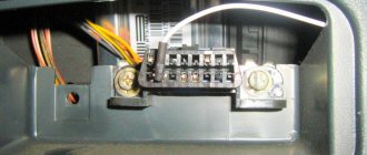
Pinout for connecting the front wiring harness on a Lada Priora VAZ 2170
From the front electrical harness, current is supplied to those electrical devices that are located in the front engine compartment of the car, such as a complex of lighting equipment, a sound device, generator and starter connections, an electric washer motor, a cooling system fan, etc. The harness is connected by plug-sockets 18,19,20 to the bundle of wires of the panel instruments, and by plug 37 to the terminal block of the rear harness.
| Contact no. | Decoding |
| 1 | Commutator DC Motor |
| 2 | Battery |
| 3 | Power generator |
| 4 | Battery, starter and front harness connectors |
| 5-7 | Front harness connectors to instrument panel harness |
| 8 | Engine compartment light breaker |
| 9-10 | Headlight units |
| 11 | Brake fluid level indicator |
| 12 | Outside temperature sensor |
| 13 | Electric windshield washer motor |
| 14 | Reverse sensor |
| 15 | Radiator cooling fan |
| 16 | Heater damper motor |
| 17 | Backup load resistor |
| 18 | Front window wiper motor |
| 19 | Main relay and fuse box |
| 20 | Heater motor |
| 21,22 | Sound signaling devices |
| A1, A2, B1, B2 | Front harness grounding locations |
The front electrical harness corresponds to serial number 2170-3724010;
Battery wiring harness with housing number 2170-3724080;
The electrical harness going from the battery to the starter is designated with the number 2170-3724070.
Designations for the rear wiring harness of the VAZ Priora
The wiring harness, located in the passenger compartment and rear of the car, has the shape of a flexible barrel with branches on which contacts are installed with blocks for docking with consumer electrical appliances. The rear electrical circuit is also connected to lighting fixtures, locks, power windows, front and rear doors.
The pinout of tips and terminals looks like this:
| Contact no. | Decoding |
| 1 | Dashboard |
| 2 | Left rear door wiring harness block |
| 3 | Right front door wiring harness block |
| 4 | Used double-glazed windows and door locks |
| 5 | Left turn signal |
| 6 | Right turn signal |
| 7 | Interior lighting module |
| 8 | Handbrake warning lamp switch |
| 9 | Left side light |
| 10 | Right side lamp |
| 11 | Interior temperature sensor |
| 12 | Interior light switch in the left front door pillar |
| 13 | Interior light switch in the front right door pillar |
| 14 | Interior light switch in the right rear door pillar |
| 15 | Interior light switch in the left rear door pillar |
| 16 | Driver's door wiring harness |
| 17 | Right rear door wiring harness |
| 18 | Rear right speaker |
| 19 | Rear left speaker |
| 20 | Cigarette lighter |
| 21 | Fuel pump block |
| 22 | Trunk light switch |
| 23 | Rear window heating device |
| 24 | Trunk light |
| 25 | Additional brake light |
| 26 | Tailgate lock switch |
| 27 | License plate lamp harness |
| 28 | Right front door harness block |
| A 1-A4 | Grounding |
| XP, XP3 | Electrical package power controller connectors |
The rear wiring harness is marked 2170-3724210.
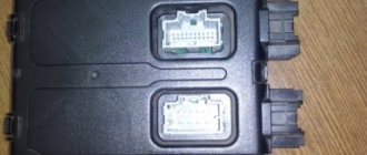
Connector pinout January 7 2
I would like to immediately convey a special greeting to the designer of AvtoVAZ, who came up with this arrangement of this block. In my opinion, I can't think of a worse place. See for yourself.
The ECU is located under the glove compartment under the passenger's feet and hidden under the upholstery. The upholstery is attached to the body on the right with a self-tapping screw.
- If your interior heater (radiator) leaks, the antifreeze will go straight to the control unit, causing almost 100% failure. Even though the Lada Granta is initially equipped with a good quality imported Visteon radiator.
- As you correctly noted, water can get in from under the hood. The rubber plugs on the Lada Granta are not of very good quality, so when they dry out, water will flow onto the controller. To prevent this from happening, check the condition of the rubber plug.
- If the drainage hole (which is shown in the video below) becomes clogged, water may flow into the cabin.
Rear license plate light pinout
According to traffic regulations, the state license plate illumination must always be in working order. For lighting, W5W incandescent lamps are connected, each with a power of 5 W.
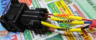
The small wiring harness for the rear license plate light (harness serial number 2170-3724214) consists of wires with cream ends and is located in the luggage compartment. The operation of the entire lighting system depends on its quality. The harness responsible for the rear license plate illumination has 3 terminals:
| № | Decoding |
| 1 | Supplying voltage to the lights illuminating the rear number |
| 2,3 | License plate lamps |
| 4 | Electric tailgate lock motor |
Pinout for left front door
Most modern vehicles are equipped with a variety of driver comfort systems, one of which is the driver's door module.
The function of the button block located on the driver's door is to control the front windows and exterior mirrors, as well as the automatic locking of the car doors. The installed auxiliary left rear wiring harness (part number 21703-724551-90) comes complete with contact carriers made of electrically conductive materials.
| Contact no. | Decoding |
| 1 | Connector for the additional rear left harness to the rear harness |
| 2 | Rear left harness connector to front left speaker |
| 3 | Electric window lift |
| 4 | Armrest control module |
| 5 | Electric drive for locking the left front door |
| 6 | Left outer rear view mirror control chip |
Front Passenger Door Wiring Harness
The electrical wiring of the left and right front doors of the car differs in the additional control buttons for mirrors and power windows on the driver's door.
The factory original front passenger door wiring harness, part number 21703-3724550 -90, duplicates the power supply from the passenger door center front keypad.
There are 7 connectors coming out of the harness.
| Contact no. | Decoding |
| 1 | Connector of the right rear additional harness to the rear harness |
| 2 | Rear left harness connector to front speaker |
| 3 | Window lift motor |
| 4 | Electric window lift switch |
| 5 | electric front passenger door lock |
| 6 | Motor controls the position of the outer right mirror and its heating |
| 7 | Connector of the right rear additional harness to the rear harness |
Where is the VAZ 2114 ECU located?
The block is located in the dashboard, directly under the tidy. To replace or dismantle, you need to unscrew the screws and remove the panel from the side, on the passenger side. Through the resulting hole you can see the ECU housing - it is installed inside a steel retainer.
To remove the electronic control unit, you need to unscrew the bolt and carefully pull out the housing, grasping the latch. Of course, it is necessary to turn off the power from the on-board network, otherwise expensive equipment can be damaged. A short circuit is the enemy of any electrical appliance, so be careful. It is advisable not only to remove ground from the battery, but also to disconnect the positive wire.
Rear door harnesses
The electrical wiring for the rear right and left doors is identical, using only two terminals. The rear door wiring harnesses are factory marked 2170-3724550-10.
| 1 | Block for connection to the rear wiring harness |
| 2 | Rear door lock motor |
Electrical diagram of the Lada Priora dashboard
The dashboard displays driving characteristics, the current state of vehicle systems that ensure traffic safety, as well as the correct operation of the entire vehicle. The instrument panel wiring diagram helps to navigate the instrument and alarm indications in cases of malfunction. The instrument panel harness is marked with number 2170-3724030.
| № | Decoding |
| 1-3 | Front harness contact group |
| 4 | Rear harness contact group |
| 5 | Power supply from the central electrical system module |
| 6 | Connecting contact system for brake light group |
| 7 | Dashboard display |
| 8 | Lighting monitoring and control module |
| 9 | Contact group of the driver's emergency airbag activation module |
| 10 | Horn switch |
| 11 | Diagnostic connector |
| 12 | On-board computer control mode switch |
| 13 | Ignition coil controller |
| 14, 15 | Supply voltage to the electric power steering control unit |
| 16 | Electrical functionality controller |
| 17 | Light switch |
| 18 | Wiper switch |
| 19 | Air flow distribution gearmotor |
| 20 | Stove control unit |
| 21 | Heater drive switch |
| 22 | Heated rear window switch |
| 23 | Onboard clock |
| 24,25 | Instrument panel harness connector to radio |
| 26 | Emergency button |
| 27 | Glove box light |
| 28 | Glove box light control button |
| 29 | Ignition system harness |
| 30 | Control unit for airbag systems |
| A1, A2, A3 | Instrument panel harness grounding locations |
| B | Mounting block block. |
Bosch M1.5.4
The pinout of the VAZ 2114 Bosch M1.5.4 ECU connector is as follows:
- 1, 20 – Control of ignition coils of cylinders 1, 4 and 2, 3;
- 3 – fuel pump;
- 4, 21, 26, 29 – Contact A, C, B, D IAC;
- 6 – fan;
- 7 – mass air flow sensor;
- 9 – speed sensor;
- 11 – DD;
- 12 – +5V output for powering sensors;
- 13 – L-line;
- 14 – mass of injectors;
- 15, 33 – control of turning on the injectors of cylinders 1, 4 and 2, 3;
- 18 – positive terminal of the battery;
- 19, 24 – mass;
- 22 – Check Engine indicator;
- 25 – air conditioner;
- 27 – positive pole from the ignition switch;
- 30 – mass of sensors;
- 34 – voltage output from the main relay;
- 41 – on air conditioner;
- 43 – tachometer;
- 44 – CO sensor;
- 45 – DTOZH. Terminal B;
- 46 – voltage at the output of the main relay;
- 47 – programming;
- 48, 49 – DPKV. Terminals B, A;
- 53 – TPDZ. Terminal C;
- 54 – fuel consumption level;
- 55 – k-Line.
Pinout of the Lada Priora instrument panel connector
The information panel installed on the dashboard contains the most data.
Each auxiliary device is connected to the control lamps on the panel. A computer chip monitors the operation of all devices. Its mission is to control the operation of the panel in accordance with its firmware. All elements of this device are mounted on an electronic board, on which connecting tracks are applied: a microcircuit with an ECU, an LCD monitor, resistances, transistors, a connector socket for the wiring harness. There are 32 cells in the connector for connecting the instrument panel.
| № | Decoding |
| 1 | Electric power steering |
| 2 | Emergency control |
| 3 | Connection to oil pressure sensor |
| 4 | Parking brake indicator light |
| 5 | Electronic anti-theft device |
| 6 | Airbag control module |
| 7 | External lighting switch |
| 8 | Right turn signal indicator and doubler |
| 9 | Left turn signal indicator and backup |
| 10 | Engine control unit |
| 11 | Disabling the passenger's front airbag |
| 12 | Seat belt warning light |
| 13 | ABS brake system unit |
| 14 | Steering column switch button |
| 15 | Brake expansion tank indicator |
| 16 | ABS safety control module |
| 17 | Main beam headlight control unit |
| 18 | Shield backlight module |
| 19 | General disadvantage of the device |
| 20 | Constant positive battery terminals |
| 21 | Ignition switch contact |
| 22 | Fuel flow meter |
| 23, 24 | Steering wheel turn switches |
| 25,26 | Overboard temperature sensors |
| 27 | Fuel sensor |
| 28 | Speed sensor |
| 29 | Coolant temperature sensor |
| 30 | Tachometer signal |
| 31 | Shield diagnostics |
| 32 | Generator Regulator Relay Terminal |
Tuning and replacement of the center console on Lada Priora and Kalina
Modern versions of cars are supplied to the market with a restyled version of the tidy. Here, a relatively old generation, navigation and a liquid crystal display appeared. Installing an updated shield requires the following steps.
Selecting the required version
There are only two types of updated designs with and without a CAN bus. The nuance is that the versions are completely identical in appearance. In order to find out which variety is suitable, you need to check the production date of the car. Machines manufactured before 06, 2012 are not equipped with this technology. The article numbers for the new devices with navigation are as follows:
- 2170-3801010-50 without CAN;
- 2170-3801010-60 with CAN.
Also in the kit you need to purchase a navigation antenna and a steering column switch of the appropriate design.
Installation nuances
For Lada Kalina versions, all devices are not equipped with a CAN module. Also the old generation of Priora. Here the installation is carried out without modifications or nuances - just snap out the old panel, remove the terminals, and mount the new set on the stock fasteners. Next, you need to install a navigation antenna on the roof and connect it to the appropriate connector. The second case is when an old panel with a CAN unit, but without navigation, is replaced with an analogue one. Here it is necessary to rearrange the contact connectors of the standard wiring from positions 10-11 to sockets No. 28-29. In case of incorrect operation of the devices, the replaced wires are swapped with each other. After the repair is completed, the counters should reset to zero.
Pinout of the lighting control unit on Priora
This switching and control combined module has several functions and is used to turn on/off parking lights, headlights, select the desired light switching mode, turn on/off fog lights, adjust the brightness of the backlight combination, control the headlight range control, on/off and control light inside the cabin and instrument lighting. The module is connected to the vehicle’s on-board network via chip No. 1118-3724500.
The standard terminal pinout on a VAZ 2170 is as follows:
| G, 56b | To the gear motor for adjusting headlights |
| 58b | Output to backlight sources |
| 31 | Weight |
| Xz | +12 volts (from terminal 15 of the ignition switch) |
| 56 | To the relay for switching high and low headlights |
| 1,3 | From rear and front fog lights |
| 2,4 | To the rear and front fog lamp relays |
| 58 | To the size lamps |
| 30 | +12 V from terminal No. 30 of the ignition switch |