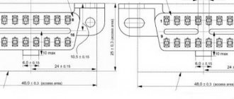
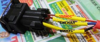
Pinout of diagnostic connector for VAZ cars
VAZ cars have a fault diagnostic system that allows you to read and decipher error codes. Most VAZ-2110 cars have an old type “January-4” controller installed. The activation of “CHECK ENGINE” is considered a malfunction detection signal. Troubleshooting in such a controller is simple - error codes are calculated starting from the number 12 and ending with 61. For more modern VAZ models, ELM-327 electronic adapters with the OBD-II program are suitable.
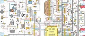
Diagram of VAZ 2110 injector 16 valves
1 - headlight 35 - instrument lighting switch 2 - front brake pad wear sensors 36 - ignition switch 3 - reverse light switch 37 - mounting block 4 - engine cooling fan electric motor 38 - recirculation valve switch 5 - sound signal 39 - controller heater 6 - right front door locking motor 40 - hazard warning switch 7 - power window relay 41 - heater control lever illumination lamp 8 - 8 A fuse 42 - glove compartment lighting lamp 9 - starter 43 - glove compartment lighting lamp switch 10 - battery 44 - cigarette lighter 11 - generator 45 - on-board control system display unit 12 - windshield washer motor 46 - ashtray lighting lamp 13 - washer fluid level sensor 47 - brake signal switch 14 - left front door locking motor 48 - locking motor left rear door 15 — power window switch of the left front door 49 — power window switch of the left rear door 16 — coolant level sensor 50 — power window motor of the left rear door 17 — windshield wiper motor 51 — socket for a portable lamp 18 — recirculation valve 52 — clock 19 - micromotor gearbox for heater flap drive 53 - gearmotor for electric window lift on the right rear door 20 - electric motor for heater 54 - power window switch at the right rear door 21 - trunk lock switch 55 - gearmotor for locking the right rear door 22 - power window switch at the right front door 56 - side turn signal 23 - electric window motor of the right front door 57 - parking brake warning lamp switch 24 - door lock system control unit 58 - driver's seat belt sensor 25 - additional heater motor resistor 59 - directional light bulb 26 - brake fluid level sensor 60 - interior light bulb 27 - electric window motor of the left front door 61 — interior air temperature sensor 28 — exterior lighting switch 62 — switch in the front door pillar 29 — instrument cluster 63 — switch in the rear door pillar 30 — rear fog light switch 64 — external rear light 31 — warning lamp fog light 65 - interior rear light 32 - rear window heating indicator light 66 - license plate lights 33 - rear window heating switch 67 - trunk light 34 - steering column switch A - blocks for connecting the rear window washer motor B - blocks for connecting the harness injection system C - to the warning light harness block D - block for connection to the on-board computer E - to the headlight cleaner harness block F - block for connection to the fuel level sensor in the electric fuel pump module G - to the rear window heating element H - block for connecting an additional signal braking J - to the trunk lock motor
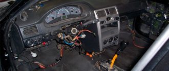
Where is the diagnostic connector located?
On different cars of the VAZ family, the socket is located in different parts of the car. Let's look at a few models as an example:
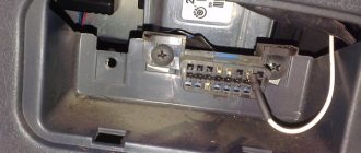
- on the VAZ-2112 , as on the 2110 , as well as the 2111 , the socket is located to the right of the driver’s seat, immediately under the column;
- on models 2108 , 2109 and 21099 , the socket you need is located under the glove compartment, on a special shelf;
- on cars with a europanel it can be found in the center of the console, near the cigarette lighter. A special decorative cover is used to disguise it;
- Lada Kalina cars the connector is near the gear shift lever, it is also hidden under a special cover;
- On a Lada Priora, look right behind the glove compartment, on the wall.
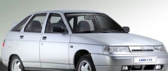
VAZ 2110
How to diagnose a car
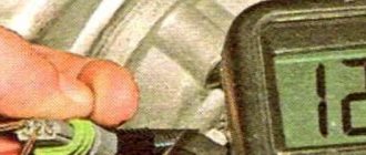
- Connect contact “B”, which has the diagnostic block and “ground”;
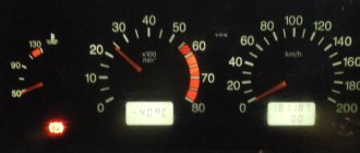
- Turn the ignition key to the third position, do not start the car;
- First, the “CHECK ENGINE” lamp displays code 12 with 3 flashes. It shows that the diagnostic programs are working. On the VAZ 2110 this happens in this order: the lamp blinks briefly 1 time (which should be considered the designation of number 1). After a pause lasting at least 2 seconds, it flashes 2 times in a row (two). So we got the number two. And this is repeated 3 times so that the driver understands these signs;
- After the diagnostic program has declared its serviceability, it will begin to display error codes, if there are any, of course. In the same way - flashes and pauses.
Deciphering error codes
The first character is a letter and indicates a fault block:
- B - body;
- C - suspension;
- P — engine (ECM, gearbox);
- U - data exchange bus.
The second character is a number, code type:
- 0 — SAE (standard);
- 1.2 - OEM (factory);
- 3 - reserved.
The third character is a number, system:
- 1, 2 - fuel system;
- 3 - ignition system;
- 4 — reduction of exhaust gas toxicity;
- 5 - idle;
- 6 - ECU or its circuits;
- 7, 8 — transmission (automatic transmission).
The fourth and fifth characters are numbers, the error code itself.
Wiring diagram for VAZ 2110 carburetor
In the instrument panel wiring harness, the second ends of the wires of white, black, orange, white with a red stripe and yellow with a blue stripe are connected to each other at the same points. The bends of the wires at the points of entry into the harness indicate the direction of their laying in the bundle.
See the complete diagram in one file below (click to enlarge):
1 – headlight 37 – instrument cluster 2 – front brake pad wear sensor 38 – rear fog light switch 3 – fan motor switch 39 – fog light indicator lamp 4 – engine cooling system fan electric motor 40 – rear window heating indicator lamp 5 – sound signal 41 – clock 6 – generator 42 – rear window heating switch 7 – oil level sensor 43 – steering column switch 8 – carburetor solenoid valve control unit 44 – block for switching wires when installing headlights of another type 9 – heater controller 45 – switch instrument lighting 10 – recirculation valve switch 46 – ignition switch 11 – illumination lamp for heater control levers 47 – connectors for connecting the headlight cleaner wiring harness 12 – switch 48 – socket for a portable lamp 13 – carburetor limit switch 49 – directional light 14 – control sensor oil pressure lamps 50 – brake light switch 15 – spark plugs 51 – interior lamp 16 – carburetor solenoid valve 52 – on-board control system unit 17 – coolant temperature indicator sensor 53 – fuel level indicator sensor 18 – ignition distributor 54 – hazard warning switch 19 – ignition coil 55 – driver’s seat belt sensor 20 – starter 56 – cigarette lighter 21 – heater fan motor 57 – ashtray backlight lamp 22 – additional resistor for heater motor 58 – glove compartment light switch 23 – speed sensor 59 – connector for on-board computer 24 – reverse light switch 60 – glove box lighting lamp 25 – micromotor gearbox for heater flap drive 61 – side turn signal 26 – recirculation valve 62 – switch in the front door pillar 27 – brake fluid level sensor 63 – switch in the rear door pillar 28 – pads for connecting the rear window washer motor 64 – parking brake warning lamp switch 29 – battery 65 – trunk light 30 – windshield washer motor 66 – interior air temperature sensor 31 – washer fluid level sensor 67 – external rear light 32 – level sensor coolant 68 – internal rear light 33 – windshield wiper motor 69 – license plate light 34 – mounting block 70 – block for connecting the rear window heating element 35 – blocks for connecting the warning light harness 71 – block for connecting an additional brake signal 36 – outdoor light switch
How the injector wiring should work, how to connect it yourself
When deciding to make major modifications to their car, or restoring it after serious breakdowns, many motorists are faced with the need to replace the wiring. In the design of any car, it is possible to replace either the under-hood wires, mainly coming from the injector, or the interior electronics that ensure the operation of application devices. In today’s article we will look at the features of repairing and replacing both types of wiring, taking VAZ cars as an example. Interesting? Then be sure to read the article below to the end.
Replacing injectors for VAZ 2110–2112 cars
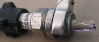
Failure of injectors causes interruptions in the supply of fuel to the cylinders and a violation of the proportions of the combustible mixture. These consequences are reflected in the vehicle's movement pattern, ignition operation, fuel consumption, idle speed stability and CO content in the exhaust.
Table: malfunctions of injectors of injection engines
| Malfunction | Manifestation of malfunction | Method of identification and accompanying symptoms of malfunction |
| clogging (coking) of the spray nozzle |
| inspection and testing of the removed injector |
| valve depressurization (nozzle leaks) |
| exceeding the CO standard by 1–1.5% for each faulty part |
| valve stuck (valve closed) | engine "troits" | lack of response from a running motor when the power supply to the injector is turned off |
| unstable valve sticking |
|
|
To replace injectors you will need the following tool:
- open-end wrenches for 17 and 13,
- hex key 5,
- socket wrenches 10 and 13,
- Phillips screwdriver.
To get to these parts, you must remove the fuel rail. The dismantling sequence for eight and sixteen-valve engines is different.
Removing the fuel rail of an eight-valve VAZ-2111 engine
- Disconnect the battery from the car body.
- Disconnect the vacuum line from the fuel pressure regulator.
- Loosen the gasoline supply and drain fittings and release the pressure. Unscrew the fuel lines and note their position.
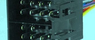
Features of injection wiring
The appearance of an injection engine power system was marked by a real breakthrough in the automotive industry. Not only have cars with internal combustion engines begun to consume noticeably less fuel, but it has also become possible to fine-tune them to a specific operating mode by adjusting the injectors. However, this state of affairs also affected the complexity of building vehicles. More precisely, the number of different electronics in the design of an injection car has become noticeably larger, and the wiring diagrams have become much more complicated.
This is due to the fact that the injector is a fine-tuning unit that requires broad information about the operation of many vehicle components. This aspect of the functioning of the injection system affected the addition of many sensors to its structure, working in conjunction with the head unit (electronic control unit). To clarify this point, we highlight the following new devices in the design of injection machines:
- Crankshaft position sensor, necessary to regulate fuel injection into the engine;
- Mass air flow sensor installed to adjust the composition of the fuel mixture;
- Knock sensor, with which the ignition timing is adjusted;
- Throttle position sensor, required for the injector to respond to pressing the gas pedal;
- Idle speed regulator, responsible for stable operation of the engine at idle speed;
- Temperature sensor that evaluates the temperature of antifreeze in the engine;
- A speed sensor, thanks to which the electronic control unit (hereinafter referred to as the ECU) selects the composition of the fuel mixture.
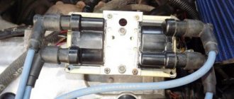
In addition to the general complication of the system, there were some simplifications in the design of the car. Perhaps the main one was the elimination of some elements of the ignition system. To be more precise, the distributor and coil have become more primitive components, being responsible solely for spark generation, while control of the spark supply has completely passed to the ECU.
Note that the complexity of the interior and engine compartment wiring of cars depends on many factors. The main ones include the make of the car and the equipment of a particular model. That is, the more functionally equipped a car is, the more electronics there are in its design and the more complex its connection diagram. In today's material, our resource decided to consider a not particularly complex system for connecting the wiring of the injector and other devices on VAZ cars. We'll talk about this in more detail later.
Injectors for VAZ 2110–2112 cars
Cars of the “tenth” family are equipped with various injection engines, each of which is designed to work with a specific model of injectors. Despite the fact that they have their own “names,” motorists usually use a “folk” classification based on color and thickness. For example: black thin ones.
This simplification usually works, but does not fully guarantee the compatibility of the injector with the engine. To avoid having to contact the chip tuner once again to correct the firmware of the electronic injection control unit, check the part number before purchasing.
Table: compatibility of injectors and engines of VAZ 2110–2112 cars
| Engine | Volume (l) | Number of valves | Controller (ECU) | Firmware | Injectors | |
| Siemens | Bosch | |||||
| VAZ-2111 | 1,5 | 8 | M1.5.4 | January-5.1 | VAZ6238 (thick gray) | 0 280 150 996 (turquoise thick) |
| VAZ-2111 | 1,5 | 8 | M7.9.7 | January-7.2 | VAZ6393 (beige thick) | 0 280 158 502 (black thin) |
| VAZ-21114 | 1,6 | 8 | M7.9.7 | January-7.2 | VAZ20734 (orange thin) VAZ20734 (yellow thick) | 0 280 158 017 (black thin) |
| VAZ-2112 | 1,5 | 16 | M1.5.4 | January-5.1 | VAZ6238 (thick gray) | 0 280 150 996 (turquoise thick) |
| VAZ-21124 | 1,6 | 16 | M7.9.7 | January-7.2 | VAZ20735 (blue thin) VAZ20735 (pink thick) | 0 280 158 022 (black thin) |
Photo gallery: injectors for VAZ 2110–2112 cars
Differences between injectors for eight and sixteen valve engines
Among some motorists there is an opinion that the injectors for the “ten” differ depending on the number of engine valves. Others believe that the determining factor is the volume of the cylinders.
Clogged injectors can cause the car to jerk when driving. Details: https://vazweb.ru/desyatka/pitanie/dergaetsya-pri-dvizhenii.html
In reality, neither one nor the other is wrong. The parts must match the engine design, model and firmware of the electronic control unit.
When replacing, it is best to install the same ones that were installed previously. Otherwise, there may be difficulties with startup and operation in transient conditions. To eliminate the shortcomings, you will have to adjust the firmware, which is almost impossible in a garage environment.
In-cylinder fuel injection has been known since the very dawn of the automobile industry. In the early 1890s, the German Rudolf Diesel and the Englishman Herbert Ackroyd-Stewart secured the rights to their own designs for an internal combustion engine running on fuel oil.
Vladimir Bekrenev
Basic tips for working with automotive electronics
Let’s immediately agree that installation, removal and any other work with car wiring are the most complex operations, which are taught in secondary specialized educational institutions. This article is for informational purposes only on working with the electronics of VAZ models and contains solely a description of the basic aspects of these procedures, so it will not be possible to learn from it all the intricacies of wiring repairs. Familiarization with these lies only through long and hard work associated with work practice in the field of automobile repair.