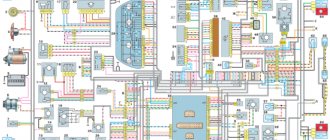
1 - injectors 2 - spark plugs 3 - ignition module 4 - diagnostic block 5 - controller 6 - block connected to the instrument panel wiring harness 7 - main relay 8 - fuse connected to the main relay 9 - electric fan relay 10 - fuse connected to electric fan relay 11 – electric fuel pump relay 12 – fuse connected to the electric fuel pump relay 13 – mass air flow sensor 14 – throttle position sensor 15 – coolant temperature sensor 16 – idle speed control 17 – oxygen sensor 18 – knock sensor 19 – crank position sensor shaft 20 – solenoid valve for canister purge 21 – immobilizer control unit 22 – immobilizer status indicator 23 – vehicle speed sensor 24 – electric fuel pump with fuel level sensor 25 – oil pressure warning lamp sensor 26 – coolant temperature indicator sensor 27 – oil level sensor 28 – phase sensor (installed on a car with a 16-valve engine) A - block connected to the anti-lock brake system (ABS) wiring harness B - block connected to the air conditioning wiring harness C - block connected to the electric fan wiring harness D - wires connected to the ignition switch (backlight lamp) E - block connected to blue-white wires disconnected from the ignition switch (when installing an immobilizer) F - to the “+” terminal of the battery G1, G2 - grounding points
The diagram uses the designation of the number of the circuit element to which this wire is connected, for example “-4-”. In some cases, in addition to the designation of the element number, it is given through an oblique fraction and the contact number, for example “-5/15-”. The diagram does not show the connection points of the pink-black, red and green with a red stripe wires. copy-paste from here thanks to him
For online configuration you need a specific ECU January 5.1 - 2112-1411020-41 January 5.1 - 2111-1411020-61 Both computers have identical content with microcircuits, etc. They understand the operation of DBP (absolute pressure sensor), have phased injection (phase sensor), oxygen sensor (lambda probe). It is these three parameters that are most important for good firmware and good engine operation. These two ECUs differ only in the firmware of 16 and 8 valves, respectively. You can buy any of the two. I took the 41st.
ECU pinout January 5.1-41 (61) 1 Ignition cylinders 1-4. 2 Ground ignition wire. 3 Fuel pump relay 4 Stepper motor PXX(A) 5 Canister purge valve. 6 Cooling system fan relay 7 Air flow sensor input signal 8 Phase sensor input signal 9 Speed sensor 10 General. Oxygen sensor weight 11 Knock sensor 12 Sensor power supply. +5 13 L-line 14 Injector mass 15 Oxygen sensor heater 16 Injector 2 17 Recirculation valve 18 +12V power supply, non-switchable 19 Common wire. Electronics ground 20 Ignition 2-3 cylinders 21 Stepper motor PXX(C) 22 CheckEngine lamp 23 Injector 1 24 Ground of stepper motor output stages 25 Air conditioning relay 26 Stepper motor PXX(B) 27 Terminal 15 of the ignition switch 28 Oxygen sensor input signal 29 Stepper motor PXX(D) 30 Weight of sensors MAF, DTOZH, DPDZ, DD, DPKV 31 Reserve high-current output 32 . 33 Oxygen sensor heater. 34 Injector 4 35 Injector 3 36 Outlet. Intake pipe length control valve. 37 Nutrition. +12V after the main relay 38 Low-current backup output 39. 40 Reserve discrete input high 41 Request to turn on the air conditioner 42 Reserve discrete input low 43 Signal to tachometer 44 Air temperature sensor 45 Coolant temperature sensor 46 Main relay 47 Programming permission 48 Crankshaft position sensor. Low level 49 Crankshaft position sensor. High level 50 Recirculation valve position sensor 51 Request to turn on the power steering 52 Reserve discrete input low 53 Throttle position sensor 54 Fuel consumption signal 55 K-line
ECU pinout VAZ 21124 16 valves injector diagram
ECU block number: 21124-1411020-30, 21124-1411020-31.32
1 — ignition coil wiring harness block to the ignition system harness 2 — ignition system harness block to the ignition coil wiring harness 3 — ignition coils 4 — immobilizer warning sensor 5 — immobilizer control unit 6 — spark plugs 7 — injectors 8 — diagnostic block 9 — ignition system harness connector to the ABS cabin group harness 10 — controller 11 — electric fuel pump 12 — ignition system harness connector to the fuel level sensor harness 13 — fuel level sensor harness connector to the ignition system harness 14 — ignition system harness connector to the injector harness 15 — harness connector injectors to the ignition system harness 16 — ignition system harness block to the side door harness 17 — speed sensor 18 — idle speed control 19 — throttle position sensor 20 — coolant temperature sensor 21 — mass air flow sensor 22 — oil pressure warning lamp sensor 23 — camshaft position sensor (phases) 24 — oxygen sensor 25 — crankshaft position sensor 26 — knock sensor 27 — canister purge solenoid valve 28 — coolant temperature indicator sensor 29 — ignition system harness connector to instrument panel harness 30 — panel harness connector devices to the ignition system harness 31 — ignition relay 32 — ignition relay fuse 33 — electric fuel pump power circuit fuse 34 — electric fuel pump relay 35 — electric fan relay 36 — controller power circuit fuse 37 — ignition system harness block to the air conditioner connector 38 — instrument cluster 39 — switch ignition 40 — electric fan of the cooling system 41 — on-board control system unit 42 — additional starter relay 43 — contacts of the 8-terminal blocks of the instrument panel harness and the front harness 44 — contacts of the 21-terminal blocks of the instrument panel harness and the rear harness 45 — trip computer 46 — diagnostic connector
A, E - to the plus terminal of the battery B1 - grounding point of the ignition coil wiring harness B2 - grounding point of the fuel level sensor harness B3, B4 - grounding points of the ignition system harness C - to the starter D - to the driver's door interior lamp switch
Source
Installing HIP9011 in January-7.2 classic blocks.
As is known, in the January-7.2 blocks from the classics there are no elements necessary for detecting detonation. Therefore, in February 2015, the idea arose to install the HIP9011 chip (TPIC8101-ATM40) in such blocks with the wiring required for its operation according to a scheme identical to the January-5.1 ECU (new hardware implementation with A5 firmware) and in the j7ls firmware to implement the ability to select a detonation detection algorithm - usual for January 7.2 or standard as January-5.1 (new hardware implementation) which was already implemented a long time ago.
In order to be able to work with HIP9011, the ECU must also have a DS2401 IC with a 4k7 resistor installed (the signal contact is connected to pin P9.3 as in the engineering unit.) This is necessary to determine by the block number the presence or absence of the HIP9011 chip in it.
After installing all parts of the control unit, they are written with a programmer (version v0.005b or higher is required). Then open the ecu.ini file in the malware editor and at the end, in the newly appeared section with the serial number of the block just recorded, add a line saying:
HIP=9011
After this, write the firmware into the block again - when writing the block, if everything is done correctly, the line << HIP 9011 activated >>
Subsequently, the programmer itself will correctly set the flags for working with HIP9011 on the connected unit.
When loading the firmware into the engineering unit from the matrix complex (loading calibrations), you must make sure that the HIP9011 flag in the firmware is cleared (if the engineering unit does not have hip9011), otherwise the program may not work correctly during setup.
Simultaneous installation of elements of the standard detonation detection circuit of the January-7.2 block and HIP9011 is impossible.
VAZ-2112 diagram
The VAZ-2112 car was produced at AvtoVAZ from 1998 to 2009, in Ukraine from 2009 to 2014. The following are color wiring diagrams (injector and carburetor) with a description of all elements for various modifications. The information is intended for self-repair of cars. Electrical circuits are divided into several blocks for ease of viewing via a computer or smartphone; there are also circuits in the form of a single picture with a description of the elements - for printing on a printer in one sheet.
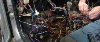
To diagnose and repair yourself, first look to see if everything is okay with the generator. Is it put on well and does not sag? This procedure must be done with all versions of the fuel system, both carburetor and injection. We check the fuses according to the electrical diagram. The reverse side of the safety block cover will also be of great help. There are clues there that the diagram will help you decipher. Replace the burnt out element and try to start the car again. You need to check whether the battery terminals are tightly connected and whether they are oxidized. Is the wire going from the battery to the generator and to the starter damaged?
Why the scanner does not connect to the VAZ 2110 ECU and how to fix it
Often car owners are faced with the problem of being unable to connect a device with a control module, because this happens:
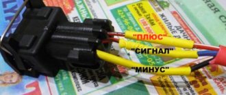
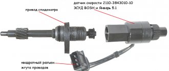
- You purchased a low-quality adapter. In this case, we are not talking about the firmware, but about the inoperability of the hardware, which is typical for faulty devices. If the card is faulty or does not initially work, it will not be possible to test the engine's functionality. Accordingly, how to connect to the control unit.
- A damaged or faulty cable that prevents the device from communicating. It is necessary to diagnose the threads for damage.
- Another reason why the connection may fail is due to bad firmware. If the software version is too old, it will be impossible to synchronize the device with the car.
Modifications of the VAZ-2112 car
VAZ-21120 . Modification with a 16-valve injection engine with a volume of 1.5 liters and a power of 93 horsepower. 14-inch wheels were installed on the car. This modification has a problem with valves bending when the timing belt breaks. The problem can be solved by increasing the depth of the grooves in the piston bottoms.
VAZ-21121 . The car was equipped with a VAZ-21114 8-valve injection engine with a volume of 1.6 liters and a power of 81 horsepower.
VAZ-21122 . Budget modification with an 8-valve injection engine VAZ-2111. The car was produced without electric windows, the wheels were 13 inches in size, and the brakes were unventilated from a VAZ-2108 car.
VAZ-21123 Coupe . Three-door, five-seater hatchback. The only two doors for entering the car are 200 millimeters wider than those of the five-door hatchback, and they are mounted on new, durable hinges. The rear arches of the car have become wider. The engine was installed with a 16-valve injection engine with a volume of 1.6 liters and a power of 90 horsepower. The car was produced from 2002 to 2006 in small quantities, the reason for this was the high cost of the car.
VAZ-21124 . Modification with a 16-valve injection engine VAZ-21124 with a volume of 1.6 liters. Produced from 2004 to 2008. For this type of engine, the problem with valve bending was solved. To do this, the depth of the grooves in the piston heads was increased (up to 6.5 mm). In addition, the design of the cylinder block was changed to achieve a working volume of 1.6 liters, for which its height was increased by 2.3 mm, and the radius of the crankshaft was increased by 2.3 mm accordingly. There were also a number of other minor changes.
Deciphering the factory markings of VAZ firmware
The software of modern ECUs is marked by the manufacturer with an alphanumeric code, divided into 5 groups.
the first group – letter and number indicates the type (family) of the controller: J4 – control units (ECU) January‑4/4.1; J5 – control units January‑5.1/5.1.1/5.1.2; V5 – control units VS‑5.1 (NPO Itelma); M1 – Motronic control units M1.5.4 (M1.5.4N); N (New) – new hardware implementation of M7 – Motronik MP7 control units.
V – VAZ cars with front-wheel drive of the 2108, 2110 families; N – family of cars with all-wheel drive VAZ;
For some reason, the exception was firmware for classics, for example, J5V26L52, etc.
third group - two digits indicate the conditional configuration number (00...99); For front-wheel drive VAZ cars, the following numbers exist:
03 – Euro-2 toxicity standards, 8-valve 1.5L engine; 05 – Euro-2 toxicity standards, 16-valve 1.5L engine; 07 – Russian standards, 16-valve 1.5L engine; 13 – Russian standards, 8-valve 1.5L engine. 26 – Russian standards, 8-valve 1.45L engine. Rear-wheel drive (classic). the fourth group - letter, indicates the ordinal software level (A...Z), the further the letter in the alphabet, the newer the software level;
the fifth group – two digits, indicates the calibration version (00...99), the larger the number, the newer the calibration.
ECU Bosch M7.9.7, M10, January 7.2/7.2+
The first group in them is one letter - the manufacturer’s code
I – ItelmaB – BoschА – Avtel
second group – one digit – controller model
1 – M10 1 – M7.9.72 – January 7.2
third group - 3 characters (numeric-alphabetic code) - symbol of the project according to the internal VAZ classification.
03E - project 2111, Euro II18E - project 2111, Euro III04D - project 21114, Euro II18D - project 21114, Euro III05D - project 21124, Euro II08D - project 21124, Euro III20E - project 21214, Euro II21E - project 21214, Euro III22H - project 21214, Euro III01C - project 11183, Euro II C02 - project 11183, Euro III02C - project 11183, Euro III73C - project 11184, Euro III73D - project 21126, Euro III C02 - project 11183, Euro III26F - project 21067, Euro II26E - project 21067, Euro II
fourth group – 1 letter – software version.
fifth group – 2 digits – calibration number
Example:
B103EQ09 – Bosch, М7.9.7, project 03E, software version – “Q”, calibration number 09I203EK34 – Itelma, January 7, project 03E, software version – “K”, calibration number 34
An attempt to classify tuning firmware designations
Since there is clearly a need to systematize firmware with changed calibrations, in the designation of firmware we will adhere to the following rules: calibrations of front-wheel drive VAZs - “V”, replaced by:
A” – for firmware for non-standard “hardware” “B” – “Butan” – firmware for operation on liquefied gas “C” – “Cam” – firmware for non-standard camshafts “D” – “Dynamic” – for dynamic firmware “E” – “Economy” – for economical firmware “M” – “Modify” – modified firmware “T” – “Tuning” – tuned firmware
Electrical diagram of VAZ-2112
Designations: 1 – Headlight, 2 – Klaxon, 3 – Main radiator fan, 4 – Starter, 5 – Battery, 6 – Generator 2112, 7 – Gearbox limit switch (reverse), 8 – Actuator in the front passenger door, 9 – Power window enable relay, 10 – Starter relay, 11 – Heater fan, 12 – Electric heater partition drive, 13 – Main pump, 14 – Washer reservoir sensor, 15 – Driver’s door actuator, 16 – Front passenger window selector, 17 – Unlock button fifth door, 18 – Heater fan resistance unit, 19 – Main wiper motor, 20 – Driver’s window lift selector, 21 – Front passenger’s window lift motor, 22 – Central locking, 23 – Exterior light switch, 24 – Brake fluid leakage sensor, 25 – Pump additional, 26 – Driver's window lift motor, 27 – PTF on indicator, 28 – PTF switch, 29 – Dashboard, 30 – Heated glass on indicator, 31 – Heated glass switch, 32 – Steering column selector switch, 33 – PTF relay, 34 – Ignition switch, 35 – Main fuse block, 36 – Illumination of heater controls, 37 – Hazard warning button, 38 – Heater control controller, 39 – Glove compartment lighting, 40 – Glove compartment lid end cap, 41 – Cigarette lighter, 42 – BSK – display unit, 43 – Ashtray illumination, 44 – 12V socket, 45 – Instrument lighting switch, 46 – Actuator in the right rear door, 47 – Right rear passenger window selector, 48 – Clock, 49 – Right rear passenger window motor, 50 – Brake limit switch (closed – pedal is pressed), 51 – Left rear passenger window motor, 52 – Left rear passenger window selector, 53 – Actuator in the left rear door, 54 – Turn signal, 55 – Handbrake limit switch (closed – handbrake on), 56 – Rear wiper motor , 57 – Navigator's lamp, 58 – Interior lamp, 59 – Temperature sensor in the heater, 60 – Limit switch for the open front door, 61 – Limit switch for the open rear door, 62 – Trunk light, 63 – Rear optics (on the body), 64 – Rear optics (on the fifth door), 65 – License plate illumination.
The letters indicate the terminals to which it is connected: A – Front speaker on the right, B – Radio, C – Injector harness, D – ESD diagnostic connector, D – Front left speaker, E – Diagnostic connector for the heater controller, G – Rear right speaker, W – Rear left speaker, I – BC connector, K – glass heater thread, L – fifth door actuator, M – Additional brake light.
Wiring diagram VAZ-2112 injector 16 valves - full view
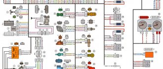
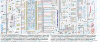
VAZ-21124 engine control circuit
Connection diagram of the VAZ-21124 engine control system with distributed fuel injection to Euro-2 emission standards (controller M7.9.7): 1 - ignition coils; 2 — nozzles; 3 - controller; 4 - main relay; 5 - fuse connected to the main relay; 6 — cooling system electric fan relay; 7 - fuse connected to the cooling system electric fan relay; 8 - electric fuel pump relay; 9 - fuse connected to the electric fuel pump relay; 10 — mass flow and air temperature sensor; 11 — throttle position sensor; 12 — coolant temperature sensor; 13 — solenoid valve for purge of the adsorber; 14 — oxygen sensor; 15 — knock sensor; 16 — crankshaft position sensor; 17 — idle speed regulator; 18 — immobilizer control unit; 19 — immobilizer status indicator; 20 - phase sensor; 21 — vehicle speed sensor; 22 — electric fuel pump module with fuel level sensor; 23 — oil pressure warning lamp sensor; 24 — coolant temperature indicator sensor; A - block connected to the wiring harness of the ABS cabin group; B — diagnostic block; B - block connected to the air conditioner wiring harness; G - to the “+” terminal of the battery; D — to the side door wiring harness block; E - block connected to the instrument panel wiring harness; G1, G2 - grounding points; I - the order of conditional numbering of plugs in the block of the immobilizer control unit; II - the order of conditional numbering of contacts in the diagnostic block.
Pinout options
Depending on the operating protocol, pinout options are allowed:
When using the standard ISO 9141-2 protocol, it is activated via pin 7, while pins 2 and 10 in the connector are inactive. For data transmission, pins numbered 4, 5, 7 and 16 are used (sometimes pin number 15 can be used).
- Documentation
With a protocol like SAE J1850 in the VPW (Variable Pulse Width Modulation) version, pins 2, 4, 5, and 16 are used. The connector is typical for American and European General Motors cars.
Using J1850 in PWM (Pulse Width Modulation) mode provides additional use of pin 10. This type of connector is used on Ford products. The J1850 protocol in any form is characterized by the non-use of pin number 7. Start of form
Of course, for many, such diagrams and descriptions of OBD2 connector pinouts are very complex and unnatural. Often, motorists prefer to periodically take their car to a specialized car service center and not even think about diagnostic connectors and, especially, about their pinouts. But it is still worth recognizing the usefulness of self-diagnosis. Experienced motorists say that it is necessary for every car owner to have a diagnostic scanner in their car to quickly check their doubts about the operation of the car, check for errors, settings and the like, which, first of all, will save significant money.
Obvious advantages of self-diagnosis via the OBD2 connector:
- Saving money, service stations charge a lot of money for simple computer diagnostics
- To promptly find out the error and understand the malfunction without the help of specialists, you don’t need to be nervous at the service station and you can avoid imaginary breakdowns, as often happens in unscrupulous services.
Good luck on your journey and in diagnosing your car!
VAZ-2112 harness diagrams
Instrument panel harness diagram
1, 2, 3, 4 – instrument panel harness pads to the front harness; 5 — block of the instrument panel harness to the side door harness; 6, 7, 8 — instrument panel harness pads to the rear harness; 9 – rear window heating switch; 10 – light signaling switch; 11 – windshield wiper switch; 12 – block of the instrument panel harness to the radio; 13 – mounting block; 14 — instrument cluster; 15 – heater control controller; 16 – heater motor switch; 17 — block of the instrument panel harness to the ignition system harness; 18, 19 — blocks of the instrument panel harness to the air supply box harness; 20 — ignition switch; 21 – fog lamp relay; 22 – sound signal relay; 23 — power window relay; 24 — starter relay; 25 – seat heating relay; 26 – external lighting switch; 27 – fog lamp switch; 28 – cigarette lighter; 29 – lampshade lighting of the glove box; 30 – glove box lighting switch; 31 – switch for rear fog lights; 32 – right steering column switch; 33 – socket for connecting a portable lamp; 34 — instrument lighting switch; 35 – brake signal switch; 36 – sound signal switch; 37 – alarm switch; 38 – air distribution drive gearmotor; 39 – VAZ-2112 illuminator; 40 — instrument panel harness block to the front harness; 41 – trunk lock drive switch; 42 – rear fog light relay.
A – grounding point of the instrument panel harness.
Source
Electrical diagram of the VAZ 21124 car
The proposed decoding schemes will help you in servicing the VAZ 21124 car. In a variant version, cars with VAZ-21114 and VAZ-21124 engines can be equipped with a starter and headlights manufactured by Bosch, fog lights, an instrument cluster with a liquid crystal display indicating the total and daily mileage, on-board computer, power windows in the front or all doors, power door locks and heated front seats. The engine power supply systems of the specified car do not have a fuel return line. The electric fuel pump module is installed in the fuel tank and includes the electric fuel pump, strainer, intake chamber, fuel pressure regulator and fuel gauge sensor. Connection diagram of the VAZ-21124 engine control system with distributed fuel injection under Euro-2 toxicity standards (controller M7.9.7) and electrical connection diagram of the 21124 Euro-3 engine control system. The description of the circuit elements is the same for both options.
1 – ignition coils 2 – injectors 3 – controller 4 – main relay 5 – fuse connected to the main relay 6 – cooling system electric fan relay 7 – fuse connected to the cooling system electric fan relay 8 – electric fuel pump relay 9 – fuse connected to electric fuel pump relay 10 – mass flow and air temperature sensor 11 – throttle position sensor 12 – coolant temperature sensor 13 – canister purge solenoid valve 14 – oxygen sensor 15 – knock sensor 16 – crankshaft position sensor 17 – idle speed control 18 – immobilizer control unit 19 – immobilizer status indicator 20 – phase sensor 21 – vehicle speed sensor 22 – electric fuel pump module with fuel level sensor 23 – oil pressure warning lamp sensor 24 – coolant temperature indicator sensor
What kind of ECUs are installed on the VAZ 2110
Previously, I already talked about which ECUs are installed on the VAZ 2114, which are interesting to read in this article! Thus, dozens of electronic control units are installed in a similar way.
January 4 - technical specifications for which VAZ 2110 models are installed
One of the most common ECUs installed on the VAZ 2110 is January 4.
Structural management system January 4
On January 4, it was installed on a first-generation VAZ 2110, produced in 1999. Of course, this is not the most advanced ECU on a VAZ, but it still has a number of advantages, which I will talk about later.
Bosch M1.5.4: advantages and disadvantages of use in the VAZ 2110
For Euro-2 toxicity standards, new modifications of the M1.5.4 block appear (has an unofficial index “N” to create an artificial difference) 2111-1411020-60 and 2112-1411020-40, which comply with these standards and include an oxygen sensor, catalytic converter and adsorber
Also, according to Russian regulations, an 8-cl engine control unit (2111-1411020-70) was developed, which is a modification of the very first engine control unit 2111-1411020. All but the first changes use a wideband beat sensor. This unit began to be produced in a new design: a lightweight, non-sealed printed case with an embossed inscription “MOTRONIC” (popularly “tin”). Later, ECU 2112-1411020-40 was also produced in this model. Replacing the design, in my opinion, is completely unfounded - sealed discs were more reliable. New modifications, most likely, have differences in the circuit diagram towards simplification, since the detonation channel in them works less correctly, the more “cans” that “ring” on the same software.
January-5 – description and technical characteristics of the VAZ 2110 ECU
In parallel with the M1.5.4 system, AvtoVAZ, together with ELCAR, developed a functional analogue of the M1.5.4 unit, which was called January-5. ". Initially, versions were produced for Euro-2 standards (2112-1411020-41), which included an oxygen sensor, catalytic converter and adsorber. Subsequently, mass production and installation of systems based on control units began:
- "January-5.1.2" at 16 (2112-111020-71).
- "January-5.1.1" for 8-valve engines (2111-1411020-71.
All these units have software and calibrations developed by AvtoVAZ. For classic cars, the modification January 5.1.3 2104-1411020-01 is used in the Euro-2 configuration, without a knock sensor.
ECU VAZ 2110 January 5.1
It differs from version 5.1 only in the unwelded elements of the detonation channel. In December 2005, NPP Avtel released spare parts (they were never supplied to VAZ) ECU January 5.1.x with modified equipment.
ECU VAZ 2110 BOSCH MP7.0H
Bosch MP 7.0 became the next generation of ECUs for dozens of VAZs; in this modification, the hardware and software were developed by Bosch, the final calibration and configuration of the systems was carried out by AvtoVAZ OJSC. This family is also expanding and is already integrated with Euro-3 standard systems for 8- and 16-valve engines of front-wheel drive vehicles, as well as for all-wheel drive VAZ-21214 and VAZ-2123 (Euro-2 and Euro-3).
The ROM in these blocks is a 256 KB FLASH chip, of which only 32 KB contains calibration tables and can be read and rewritten. Chances are you can write the entire 256 KB but only read 32 KB. Reading/writing of these blocks (without opening the blocks) is only supported by the SMS-Software Combiloader program. It is also possible to program the flash using an external programmer via an adapter connected to the ECU bus.
ECU VAZ 2110 BOSCH MP7.0H
This ECU uses a 16-bit B58590 processor (internally branded Bosch), a 20-bit bus, and uses 29F200 flash memory as ROM to store software and calibrations. ECUs of different modifications differ in hardware. The ECU for E3 (-50) standards has an additional heater driver for the 2nd oxygen sensor. There may also be differences depending on the DTV channel. A beautiful paper sticker (there is one) above the standard nameplate is most likely the idea of OPP, such blocks were installed on some Niva and Nadezhda, which were replaced from the regular Niva with OPP. This type of ECU supports non-switchable driver diagnostics. Therefore, when installing LPG on them, it is absolutely necessary to use a constant stop of the injectors.
Electrical system diagram of VAZ 21124 in the engine compartment
- electric fan (No. 3);
- electric fan switch relay (No. 22);
- coolant temperature sensor (No. 7);
- electric fuel pump with fuel level sensor (No. 30);
- fuel pump activation relay (No. 21);
- electric heater of the fuel system inlet pipe (No. 4);
- power relay and heater protection fuse (No. 23 and 24);
- air temperature sensor and absolute pressure sensor (No. 5 and 6);
- engine control controller (No. 13);
- SUD fuse box (No. 20);
- fuse box (No. 27);
- ignition relay 21124 (No. 26);
- spark plugs (No. 28);
- car starter relay (No. 25);
- battery (No. 18).
Electrical diagram of the VAZ-21104 ECM with controller 21124-1411020-30/31/32
1 — block of the ignition coil wiring harness to the ignition system harness; 2 — block of the ignition system harness to the ignition coil wiring harness; 3 — ignition coils; 4 — immobilizer warning sensor; 5 — immobilizer control unit; 6 — spark plugs; 7 — nozzles; 8 — diagnostic block; 9 — block of the ignition system harness to the ABS cabin group harness; 10 - controller; 11 — electric fuel pump; 12 — block of the ignition system harness to the fuel level sensor harness; 13 — block of the fuel level sensor harness to the ignition system harness; 14 — block of the ignition system harness to the injector harness; 15 — injector harness block to the ignition system harness; 16 — block of the ignition system harness to the side door harness; 17 — speed sensor; 18 — idle speed regulator; 19 — throttle position sensor; 20 — coolant temperature sensor; 21 — mass air flow sensor; 22 — oil pressure warning lamp sensor; 23 - phase sensor; 24 — oxygen sensor; 25 — crankshaft position sensor; 26 — knock sensor; 27 — solenoid valve for purge of the adsorber; 28 — oil level sensor; 29 — coolant temperature indicator sensor; 30 — block of the ignition system harness to the instrument panel harness; 31 — block of the instrument panel harness to the ignition system harness; 32 — ignition relay; 33 - ignition relay fuse; 34 — fuse for the electric fuel pump power supply circuit; 35 — electric fuel pump relay; 36 — electric fan relay; 37 — controller power supply fuse; 38 — ignition system harness block to the air conditioner connector; 39 — instrument cluster; 40 — ignition switch; 41 — electric fan of the cooling system; 42 — on-board control system unit; 43 — starter relay; 44 — contacts of the 8-terminal blocks of the instrument panel harness and the front harness; 45 — contacts of the 21-terminal blocks of the instrument panel harness and the rear harness; 46 — trip computer; 47 - diagnostic connector.
Car fuses - number, current and description
F1 5 Lighting lamps: numbers, instruments, dimensions on the dashboard, left dimensions, trunk lighting F2 7.5 Low beam in the left headlight F3 10 High beam in the left headlight F4 10 Right front fog lamp F5 30 Door windows F6 15 Portable lamp, cigarette lighter F7 20 Radiator fan, horn F8 20 Heated rear window F9 20 Windshield washer and cleaner F10 20 Reserve F11 5 Clearance on the right side F12 7.5 Low beam in the right headlight F13 10 High beam in the right headlight F14 10 Fog lamp, left F15 20 Heated seats 21124 F16 10 Hazard signal, turn signals F17 7.5 Brake light, ignition switch illumination, interior lighting F18 25 Cigarette lighter, glove compartment light, interior heater F19 10 Reversing lamp, brake light monitoring F20 7.5 Rear fog lights headlights
Source
Car diagnostics
The appearance of a lit “Check Engine” lamp on the instrument cluster signals the driver that a problem has arisen in the vehicle’s electrical system. You need to understand that checking the vehicle yourself and at a service station can give different results. Special equipment available to professionals will allow more accurate detection of faults.
Self-diagnosis
On a VAZ 2115, the owner can do independent diagnostics and find out what errors are stored in the memory of the engine control unit. The procedure is carried out by calling up fault codes on the dashboard or using a diagnostic adapter.
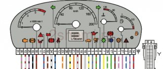
To carry out diagnostics on the electronic instrument panel, you must perform a certain sequence of actions:
- Sit in the driver's seat of the car, insert the key into the ignition and press the daily mileage reset button located on the instrument cluster.
- Turn the lock key to the ignition switch position.
- Release the key, starting the self-diagnosis process. Visually, this will look like turning on the backlight, all signal lamps, possible symbols on the LCD screens and testing the instruments (the arrows will move across the entire scale in both directions).
- Press the key again and release. The second press displays the software version of the instrument cluster on the screen located under the speedometer (inscription like Uer x. x).
- Press the key again, after which the errors in the memory will be displayed on the screen.
Instrument cluster VAZ 2115, the button is located on the right side of the speedometer
We recommend: VAZ 2114: what to do if the starter turns for a long time and does not start?
The driver can perform self-diagnosis on the electromechanical panel and the “January-4” control unit according to the following sequence:
- Turn off the ignition.
- Open the diagnostic connector cover located on the center console.
- Connect contact B to the negative terminal of the battery (to the body). Contact A, connected to the engine crankcase, is suitable for this.
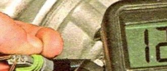
- Turn on the ignition. The “Check Engine” lamp will flash code 12, which means the diagnosis has begun. The light signals are given as follows - a long flash, then a pause (about 2 seconds), two short flashes, a long pause (about 3 seconds). Signal 12 is sent three times. If there is no signal, the diagnostic system is inactive or faulty. After this, the Check Engine light will flash and list the errors in memory. Each code is repeated three times. If there are no errors in the memory, code 12 will continue to be transmitted.
Electromechanical instrument cluster Pinout of diagnostic connector
To read controller errors, a special K-Line adapter is used, which is connected to the diagnostic connector using a connector. This connector is located on the center console behind a plastic plug (below the cigarette lighter and ashtray). The adapter has a cord with a USB connector at the end that connects to any laptop. A special program for reading and resetting errors must be installed on the device (OpenDiagFree version 1.4 or 1.6).
The procedure for reading errors is quite simple, you need to:
- Check the level of process fluids.
- Open the connector cover and turn on the ignition.
- Connect the adapter or scanner to the diagnostic socket.
- Launch the software on the laptop.
- View available errors in the program dialog box.
- Decrypt the codes using the program interface or decryption table.
- Eliminate the causes of malfunctions and re-diagnostics.