Disconnect the wiring from the pump.
Using a Phillips screwdriver, remove the screws, and then remove the hatch cover located above the tank. The second ends of the orange wires are brought together to a point connected to plug “3” of the “X4” block of the mounting block. Their price is small, but their help and impact are significant. Wiring VAZ 2115. Part 2.
"Check engine" indicator lamp.
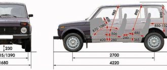
Table 7. For added safety, the model was supplemented with a brake signal and rear lighting. Thanks to different engines, the VAZ engine compartment wiring has its own design differences: the VAZ model has larger wiring harnesses due to the installation of additional sensors and electronic devices; The connectors of some electrical circuits have also changed; The layout of some of the wires has changed.
In addition, the layout of some of the electrical components as a whole was changed. On cars with an injection engine there is an additional unit located in the front passenger's feet.
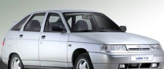
When the lock socket illumination is on and the engine is running, the anti-theft locking device blocks the VAZ starter from re-engaging. The luggage compartment has become more spacious and convenient due to the increase in the trunk lid.
relays and fuses for the computer, Carlson and fuel pump
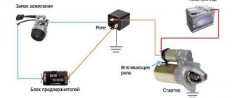
VAZ starter connection diagram
VAZ cars use starters, which are a DC electric motor with an electromagnetic two-winding traction relay and a roller freewheel clutch (overrunning clutch). Starters are used to provide the minimum crankshaft speed required to start the engine. The starter is powered in starting mode from the battery.
The starter relay is connected to the power circuit, thereby closing and opening the circuit, depending on how fast the crankshaft rotates. The starter design on all cars is the same, with only minor design differences. If you understand how the starter works in one car, you can easily figure it out in another.
To prevent a starter failure from taking you by surprise, let’s look at how to replace it yourself. But first, read the theory and study all the options for starter connection diagrams for different models of VAZ cars, collected by the editors of 2 Schemes.ru from familiar auto electricians.
VAZ 2101 starter connection diagram
- starter;
- holding winding of traction relay;
- ignition switch;
- generator VAZ 2101;
- fuse box;
- pull-in winding of the traction relay;
- accumulator battery.
Under normal loads, the current generated by the starter is 150 A. When heavy loads occur, for example in winter, the resulting current can reach 500 A. This is a serious test for this electrical unit, so it is not recommended to keep the key on the start for more than 10 seconds, and repeated starting attempts must be made with a break of at least a minute.
VAZ 2106 starter connection diagram
- starter;
- generator;
- accumulator battery;
- pull-in winding of the traction relay;
- ignition switch;
- traction relay holding coil
| 1 – drive side cover; | 14 – relay cover; |
| 2 – retaining ring; | 15 – contact bolts; |
| 3 – restrictive ring; | 16 – collector; |
| 4 – drive gear; | 17 – brush; |
| 5 – overrunning clutch; | 18 – armature shaft bushing; |
| 6 – drive ring; | 19 – cover from the collector side; |
| 7 – rubber plug; | 20 – casing; |
| 8 – drive lever; | 21 – shunt coil of the stator winding; |
| 9 – relay anchor 2106; | 22 – body; |
| 10 – holding winding of the traction relay; | 23 – stator pole fastening screw; |
| 11 – pull-in winding of the traction relay; | 24 – anchor; |
| 12 – relay coupling bolt; | 25 – armature winding; |
| 13 – contact plate; | 26 – intermediate ring. |
Starter diagram VAZ 2108, 2109, 21099
Electric current enters the starter circuit from terminal “30” of the generator. Next, through block Ш8 (Х8) of the mounting block (pins 5,6), block Ш1 (Х1) - pink wire, to the ignition switch. The driver turns the key in the ignition to turn on the starter (position 2) and closes the contacts (50, 30). After which the ignition switch, through the red wire, current flows to block Ш1 (X1) of the mounting block (pin 8), then block Ш5 (Х5) (pin 4), starter switch relay (pin 85). The relay is activated. From terminal “30” of the start relay, current flows to terminal “50” of the starter traction relay, energizing its winding. The traction relay is activated, activating the starter.
The starter electrical circuit uses a switching relay 111.3747-10.
- Screw securing the protective cap.
- Protective cap.
- Retaining half ring.
- Rear cover fastening nut.
- Back cover.
- Brush springs.
- Brush guides (outer part).
- Brushes.
- Stator.
- Anchor.
- Drive lever.
- Drive unit.
- Restriction ring.
- Retaining ring.
- Drive lever axis.
- Screws for securing the traction relay.
- Front cover.
- Plastic sealing ring for the lid.
- Tie rods.
- Rubber plug.
- Traction relay core.
- Return spring.
- O-ring for traction relay.
- Traction relay.
- Sealing washer.
- Adjusting washers.
Tips for replacing the door lock cylinder on a VAZ 2114
Often, when repairing a door handle lock, it turns out that severe wear of the part leads to the need to replace several elements of the device. You can try to restore the lock, but such repairs will not help for long and after a while you will have to start solving this problem again.
When using the car for a long time, it is recommended to inspect the door locks from time to time and replace the part if necessary. Before removing the lock cylinder from the package or from the door handle, be sure to insert the key into the lock hole. Otherwise, this threatens the pins falling out of the lock grooves, which will be problematic to put in place.
On a VAZ 2114, replacing the door lock cylinder is a job that you can do yourself, if you have free time and the necessary tools. To change the lock cylinder you will need:
- open-end wrenches “8” and “10”;
- pliers;
- WD-40 lubricant;
- flat and Phillips screwdriver;
- new lock cylinders and springs for VAZ 2114.
The price for a set of door lock cylinders with a trunk lock for a VAZ 2114 manufactured by VAZ with article number 21140610004520 is 400 rubles, and its analogue with article number 21140-610004520 from the manufacturer DAAZ is 450 rubles. The cost is indicated for spring 2022 in Moscow and the region.
1Use a Phillips screwdriver to unscrew the three screws at the bottom of the trim.
2Remove the cover. We take the front shutter glass position switch out of the pocket along with the wiring harness block, disconnecting it from the wire switch.
3Using a screwdriver, remove the armrest handle cap.
4Use a Phillips screwdriver to unscrew the 2 screws securing the armrest handle to the inner door panel.
5Press the fasteners securing the inner lock handle trim to the door panel...
7 Carefully, using a screwdriver, remove the six pins from the holes in the door panel and remove the door card.
8Using an 8 wrench, unscrew the two nuts securing the outer lock handle. First one...
10 Disconnect the outer handle rods and the lock switch from the internal lock.
11Remove the outer lock door handle with rods.
12Then remove the pin from the end of the rods.
14Remove the plastic rod end from the door lock cylinder.
15Remove the locking spring by removing its ends from the slots on the cylinder and on the lock handle.
16 We take out the old lock cylinder along with the key.
17Unpack the new set of larvae. Having previously lubricated all the rubbing parts with grease, we insert the lock into the door handle.
18Install a new cylinder return spring.
19When turning the key, the key should return back from any position.
20Install the pin on the tip of the rotary rod. The handle is assembled. We carry out further assembly in reverse order.
The larva has a cylindrical shape, which is activated when the key is turned in the well. If the mechanism jams and makes it difficult to open/close, then one day the driver simply will not be able to get behind the wheel of his car. Therefore, if the device does not operate correctly, it is recommended to replace the door lock cylinder with a VAZ 2114.
Starter circuit for VAZ 2110, 2111, 2112
Starters of type 57.3708 were installed on VAZ-2110 cars and had the following technical characteristics:
- Rated power 1.55 kW
- Current consumption at maximum power no more than 375 Amperes
- Current consumption in the inhibited state is no more than 700 Amperes
- Current consumption in idle mode no more than 80 Amperes
The connection diagram for the starter for the ten is shown above, here is its explanation:
- battery
- generator
- the starter itself
- egnition lock
| 1 – drive shaft; | 20 – contact bolts; |
| 2 – front cover bushing; | 21 – output of “positive” brushes; |
| 3 – restrictive ring; | 22 – bracket; |
| 4 – gear with the inner ring of the overrunning clutch; | 23 – brush holder; |
| 5 – overrunning clutch roller; | 24 – “positive” brush; |
| 6 – drive shaft support with liner; | 25 – armature shaft; |
| 7 – planetary gear axis; | 26 – tie rod; |
| 8 – gasket; | 27 – back cover with bushing; |
| 9 – lever bracket; | 28 – collector; |
| 10 – drive lever; | 29 – body; |
| 11 – front cover; | 30 – permanent magnet; |
| 12 – relay anchor; | 31 – armature core; |
| 13 – holding winding; | 32 – armature shaft support with liner; |
| 14 – retractor winding; | 33 – planetary gear; |
| 15 – traction relay; | 34 – central (drive) gear; |
| 16 – traction relay rod; | 35 – carrier; |
| 17 – traction relay core; | 36 – gear with internal teeth; |
| 18 – contact plate; | 37 – layering ring; |
| 19 – traction relay cover; | 38 – hub with the outer ring of the overrunning clutch. |
Starter solenoid relay
The starter relay is called a pull-in relay. This is due to the principle of its operation - it performs the function of connecting the starting device to the electrical circuit and connecting its armature to the crankshaft. It happens like this: when no current is supplied to the windings of the device, its armature, under the action of the return spring, remains in the forward position. The same spring, through a special fork, holds the Bendix gear, preventing it from engaging with the crankshaft flywheel ring.
By turning the key in the ignition, we supply current to the winding of the device. Under the influence of an electromagnetic field, the armature is fed back (pulled into the housing), closing the starter power contacts. The Bendix gear also moves, engaging with the flywheel. At the same moment, the retracting winding is turned off, and the holding winding comes into play. The force from the starter shaft is transmitted through the gear to the flywheel, causing the crankshaft to rotate until we no longer hold the ignition key in the start position.
What functions does the solenoid relay perform:
- Protects the starter from shorting contacts in the ignition.
- In order to turn off the power to the starter in a situation where the engine is running and the key shows the “starter” mode.
- Provides relief of contacts in the ignition switch.
When the engine starts, voltage from the generator goes to the relay coil. Then the gears of the drive system begin to work, due to which a magnetic field is created. The flywheel of the propulsion system is working. The gear begins its work thanks to the holding winding, while the bolts are closed. When the key is returned to the ignition switch, the winding is de-energized, thus disconnecting the gear and flywheel. This scheme applies to modern cars, including VAZ models.
If the starter makes a loud noise, the pole or starter could be loose. In the first situation, strengthen the fastening by tightening the screw, and in the second, secure the starter. If you disassemble the starter and see that the clutch is starting to slip, then the only thing you need to do is replace the starter drive.
Steering lock testing
If you don't check the steering lock, you may encounter certain problems in the future. Therefore, do not waste your time on this event. It consists of removing the key from the ignition and turning the steering wheel at a slight angle.
- If there is no lock, you will need to slightly adjust the position of the lock. Make sure it fits into the groove located on the steering shaft.
- If the locking is effective, you will only need to tighten the four installed breakaway bolts until they stop. Twist until the heads break.
When the lock installation is completed and the test has passed, do not forget to connect the device to power and start the engine. If it starts, all systems dependent on the ignition switch are working, you can fully begin reassembly. Follow the reverse instructions for removing the casing and steering column switches. It would not be amiss to check the condition of certain nodes along the way. It is quite possible that some of them also need replacement or a little preventive maintenance.
Connecting wires to the starter
Connecting a starter to a VAZ - instructions. Attach the relay in a convenient place (for example, a washer reservoir). Connect the wires to the starter. Then remove the red wire located on the flat terminal of the relay, and you need to make a connection with the connector of the male wire and the wire from the new relay.
Place the wire with a ring terminal for 8 mm on the positive side of the starter and tighten it with a nut. Place the wire of the new “female” type relay onto the contact that was released at the traction relay. This wire will transmit the positive to the coil. Using a clamp, tighten the new wire and the stock one together. Screw a small length of wire from the coil. Now you can turn on the new relay.
Source
How to set the ignition yourself?
Precise ignition adjustment on the VAZ 2115 injector is performed using a special strobe light. If this is not possible, you can set the ignition on the VAZ by spark.
To do this, follow these steps:
- First of all, the engine is warmed up until it reaches operating temperature.
- The distributor does not need to be removed, but only relaxed.
- You need to remove the central wire from the distributor.
- The piston in the 1st cylinder must be at TDC (the marks are set differently on 8 and 16 valve engines).
- Now you need to hold the short-circuit wire with your left hand and turn on the ignition.
- Use your right hand to adjust the distributor counterclockwise, while keeping the high-voltage wires above the metal.
- Then similar actions are performed, turning the distributor clockwise until a spark appears.
- At this point, the alignment ends, and the distributor is fixed in its regular place.
With the ignition set correctly, the car will operate without interruption with optimal fuel consumption and maximum power.
VAZ ignition switch pinout
The ignition switch in cars of the VAZ family fails from time to time due to weakening of the contact posts or burning of the contacts inside it. It also happens that the cams of a plastic roller are produced. You can disassemble the lock and clean it, but it’s better to just replace it with a new one, considering that it costs pennies compared to imported locks.
But if connecting the wires together did not result in the starter operating (or it did not turn on the first time), check the solenoid relay on the starter. The contact spots on it may also burn out, which will prevent the circuit from closing normally. Alternatively, you can use a screwdriver to short-circuit the two large terminals on the solenoid relay (before doing this, put the car in neutral and use the handbrake). When closed, the starter should begin to spin vigorously. If this happens, remove and change the solenoid relay. If the starter rotates “sluggishly” when it closes, you will have to remove it and check the condition of the brushes.
All operations are performed with your own hands, without the help of car service specialists. Moreover, the price of an ignition switch on a VAZ2106 is up to 100 rubles. To replace it, you will need to know the pinout of the wires coming from it, for which the editors of the site 2 Schemes.ru have prepared a large reference material.
The ignition switch is designed not only to start the engine - it performs several functions at once:
- supplies voltage to the vehicle’s on-board network, closing the circuits of the ignition system, lighting, sound alarm, additional devices and instruments;
- at the driver’s command, turns on the starter to start the power plant and turns it off;
- turns off the power to the on-board circuit, preserving the battery charge;
- protects the car from theft by fixing the steering shaft.
Checking the Lada Samara ignition module
The correct functioning of the ignition module not only has a significant impact on the start of the vehicle’s power plant, but also ensures the stability of its operation in all modes. To carry out a complete diagnosis of this electronic device, you need quite complex equipment, available only in large specialized workshops. However, you can check the functionality of the ignition module yourself in an amateur garage. The only logistical support for this test will be a multimeter, or tester.
Attention! When using a donor car for testing, do not forget that only the first Lada Samara models were equipped with the ignition module, as a separate device. Cars of later releases are equipped with separate type devices (the switch is included in the electronic control unit). The procedure for replacing the ignition module includes the following measures:
The procedure for replacing the ignition module includes the following steps:
Another method involves measuring the resistance of individual module elements using a multimeter (tester). Using the tester probes, we close the “paired” terminals of the module, which provide connection to high voltage wires, and measure the resistance value.
There is another, so-called “folk” method, or the “shake-up” method. With the power plant running, lightly tap the module. Despite all the “technical non-scientific” nature of such manipulations, they are capable of producing results. True, only in the case when the contact of the elements inside the housing is broken.
Sources
- https://avtozam.com/vaz/2115/zazhiganie-remont-zamena-i-nastrojka/
- https://remontautomobilya.ru/modul-zazhiganiya-vaz-2114-princip-raboty-vozmozhnye-neispravnosti-i-zamena.html
- https://vipwash.ru/sistema-zazhiganiya/modul-zazhiganiya-vaz-2115
Pinout of the ignition switch VAZ-2101 - VAZ-2107
The ignition switch on these cars is located to the left of the steering column. It is fixed directly to it using two fixing bolts. The entire mechanism of the device, except for the upper part in which the keyhole is located, is hidden by a plastic casing.
On the visible part of the ignition switch housing, special marks are applied in a certain order, allowing inexperienced drivers to navigate the lock activation mode when the key is in the hole:
- “ ” – a mark indicating that all systems, devices and instruments that are turned on using the lock are turned off (this does not include the cigarette lighter, interior lighting, brake light, and in some cases the radio);
- “ I ” is a mark informing that the vehicle’s on-board network is powered from the battery. In this position, the key is fixed independently, and electricity is supplied to the ignition system, to the electric motors of the heater and windshield washer, instrumentation, headlights and light signaling;
- “ II ” – engine start mark. It indicates that voltage is applied to the starter. The key does not lock in this position. If you release it, it will return to the "I" position. This is done so as not to subject the starter to unnecessary loads;
- “ III ” – parking mark. If you remove the key from the ignition in this position, the steering column will be locked with a latch. It can only be unlocked by inserting the key back and turning it to position “0” or “I”.
The ignition switch has five contacts and, accordingly, five terminals, which are responsible for supplying voltage to the desired unit. All of them are numbered for convenience. Each pin corresponds to a wire of a certain color:
- “50” – output responsible for supplying current to the starter (red or purple wire);
- “15” – terminal through which voltage is supplied to the ignition system, to the electric motors of the heater, washer, and instrument panel (double blue wire with a black stripe);
- “30” and “30/1” – constant “plus” (pink and brown wires, respectively);
- “INT” – external lighting and light signaling (double black wire).
How to check the ignition switch?
Breakdowns can be external and internal. External ones include loss or defect of the key, as well as visible damage to the lock itself. Sometimes you can see a piece of debris stuck in it. It is also worth checking the reliability of the connection of the block. Perhaps the wires simply came loose. Internal defects are associated with failure of the part itself or its electrical wiring. To determine such a malfunction, you will need a multimeter.
Diagnostics is carried out according to the following algorithm:
- Set the measuring device to ohmmeter mode;
- Remove the steering column cover;
- Disconnect the block with wires;
- Inspect the connector and find pins 7 and 4 on it;
- Connect the multimeter probes to them;
- Set the key to the “Ignition” position;
- Connect the ohmmeter probes to pins 7 and 3, then turn the key in the lock to the “Engine Start” mode.
If the lock is working properly, then during measurements the multimeter will show no resistance. If it is, it means the part has failed. It is usually beyond repair. Therefore, replacement will be required.
Checking with a multimeter will allow you to accurately determine the faulty element. In case of visual damage or loss of the key, replacement of the part is required. If self-diagnosis does not help identify the problem, you should consult an auto electrician.
Pinout of lock VAZ-2108, VAZ-2109, VAZ-21099
Pinout according to the old type
Pinout of the VAZ-2109 ignition switch with unloading relay:
- comes +12V in position I, II, III (parking)
- comes +12V in position I, II, III (parking)
- comes +12V in position III (parking)
- position I, +12V goes out after turning on the ignition (contact 15/2), disappears at start (II);
- position I, +12V goes to the starter (pin 50);
- position I, +12V goes away after turning on the ignition (pin 15), does not disappear when starting II;
- +12V comes from the battery (pin 30);
- comes +12V constantly.
New pinout type
Pinout of the new VAZ-2109 ignition switch:
- comes +12V constantly
- comes +12V constantly
- +12V arrives after turning on the ignition (pin 15), does not disappear when starting II;
- +12V arrives after turning on the ignition (contact 15/2), disappears at start (II);
- position I, +12V goes to the starter (pin 50);
- +12V arrives after turning on the ignition (pin 15), does not disappear when starting II;
- +12V comes from the battery (pin 30);
- comes +12V constantly.
Installation and connection of a new lock
Now that the old ignition switch has been removed, you can begin installing the new one. In order to do this, you need:
- Take a new lock, insert the key into it and turn it to position number one. This is necessary so that the latch responsible for locking the steering shaft goes inside and does not interfere with the installation process.
Breakaway bolts to prevent the lock from being stolen
- Reinstall the lock and tighten the release bolts. There is no need to tear off the bolt heads right away, so that if something happens, you won’t have to work with a chisel again. This can be done later.
Do not immediately tear off the bolt heads
- Connect the electrics of the new lock to the mating part of the car; you should be careful when working with electricity.
Ignition switch terminal VAZ 2114
Pinout of lock VAZ-2110, VAZ-2111, VAZ-2112
Pinout of the ignition switch VAZ-2110:
- comes +12V for the microphone of the sensor of the inserted key;
- the mass comes when the driver's door is open;
- +12V goes to the starter (pin 50);
- +12V goes out after turning on the ignition (pin 15);
- +12V goes out when the key is inserted to pin 5 of the BSK;
- comes +12V to illuminate the lock cylinder;
- +12V comes from the battery (pin 30);
- not used.
Why you may need to replace the ignition switch
There can be several reasons for this problem, the most common of which are:
- The lock is broken; after all, it is constantly subject to wear and tear.
- Lost keys.
- Damage caused by attempted theft.
- Malfunction of the connector with wires.
The malfunction can be easily determined when the engine is turned on, if the sound of the starter is not heard, the relay clicks, or the electrical equipment simply does not turn on.
Pinout of lock VAZ-2113, VAZ-2114, VAZ-2115
Pinout of the ignition switch VAZ-2113, 2114, 2115:
- comes +12V for the microphone of the sensor of the inserted key;
- the mass comes when the driver's door is open;
- +12V goes to the starter (pin 50);
- +12V goes out after turning on the ignition (pin 15);
- +12V goes out when the key is inserted to pin 5 of the BSK;
- comes +12V to illuminate the lock cylinder;
- +12V comes from the battery (pin 30);
- not used.
The structure of a car ignition switch
- Locking rod
- Frame
- Roller
- Contact disc
- Contact sleeve
- Block
- Protrusion of the contact part.
The lock mechanism is connected to many wires. They continue from the battery, connecting all the electrical devices of the car into a single chain. When you turn the ignition key, the electrical circuit is closed from the “-” terminal of the battery to the ignition coil. As a result, the current passes through the wires to the ignition switch, through its contacts it is directed to the induction coil, after which it returns back to the “+” terminal. As electricity passes through the coil, it generates high voltage, which it transmits to the spark plug. Therefore, the key closes the contacts of the ignition circuit, thereby starting the car engine.
Replacing the ignition module yourself
So, first of all, we are looking for a module (for those who don’t know). The PVNs from the spark plugs go to it.
- Remove the negative terminal from the battery
- Disconnect the wire block from the module
- Disconnect the PVN
- Unscrew the module itself and remove it
- Now install the new module and reassemble in reverse order.
When installing, do not confuse the position of the PVN on the reel.
Helpful note! If you are installing a new coil and old wires, pay attention to them. If there are yellow stripes at the tips of the spark plugs and wires, then the wires need to be replaced. After replacing the module, you need to check its operation
We start the engine and enjoy the work done.
After replacing the module, you need to check its operation. We start the engine and enjoy the work done.
In the article brought to your attention, we will pay attention to an electronic device called the ignition module of the VAZ 2115 car. Or, more precisely, its description, circuit diagram and performance testing. This module includes two high-voltage transformers and two control units (electronic), enclosed in a durable plastic case with four high-voltage wire outputs
Electronic control units are also commonly called ignition coils, and one of them - “working” - is connected to the spark plugs of the first and fourth cylinders of the power unit, the other - “idle” - with the spark plugs of the second and third.
This module consists of two high-voltage transformers and two control units (electronic), enclosed in a durable plastic case with four outputs of high-voltage wires. Electronic control units are also commonly called ignition coils, and one of them - “working” - is connected to the spark plugs of the first and fourth cylinders of the power unit, the other - “idle” - with the spark plugs of the second and third.
The VAZ 2115 ignition module is controlled by a controller whose operating functions include processing data received from vehicle system sensors: coolant temperature, rotation speed and position of the crankshaft, air flow, presence of detonation, etc.
The circuit diagram and connection diagram of this electronic device is presented below.
The only negative point in the operation of this electronic device is its complete inability to repair. However, even a novice car enthusiast can replace it on his own.
- Unstable operation of the power plant when accelerating the vehicle.
- Decrease in engine power.
- “Intermittent” idle speed.
- Malfunction of paired (1/4 - 2/3) engine cylinders.