01/03/2020 6,551 Electrical wiring and electrical circuits
Author:Ivan
The functioning of any car is impossible without the operation of electrical circuits and components. The ability to read and understand the electrical diagram of a VAZ 2109 will allow the owner to independently repair the car in the garage and on the road.
[Hide]
Reasons for failure of the main vehicle systems
Many car malfunctions, initially perceived as mechanical, arise due to damage to the electrical wiring.
Some of the most common problems are described below:
- The starter turns the shaft, but the engine does not start. One of the reasons for engine inoperability may be a failure of the ignition system wiring harness or a blown fuse or relay. Faulty elements must be found and replaced with new ones. On machines with distributed injection, parts of the wiring of the engine control unit or fuel pump may be damaged. On a carburetor car, the faulty area can be found with a tester by calling each wire. On the injection VAZ 2109, it is possible to carry out diagnostics, which will show a unit with a damaged or broken circuit.
- When you turn the key, the starter does not work, the indicator lamps light up at normal intensity. The reasons may be a break or oxidation of the wires going to the starter, or the ignition switch.
- When you turn the key, the starter does not work and all the lights go out. A typical sign of a discharged battery or poor contact of the power wires with the battery terminals.
- After starting the engine, the charging indicator lamp does not go out. Most likely, the wiring has broken, the contacts on the generator have oxidized, or the drive belt is broken.
- Unusually bright headlights or pulsating light indicate damage to the voltage regulator on the generator. On injection machines, such a breakdown can cause the Check Engine lamp to turn on.
- A non-lit front or rear light indicates a failure of the lamps, fuse or wiring harness going to this unit.
- When you turn on the turn signal, all the lamps in the rear light begin to blink. A standard problem with all first-generation front-wheel drive VAZs, the cause of which is oxidation and short-circuiting of the circuit board tracks inside the lamp.
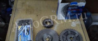
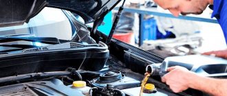
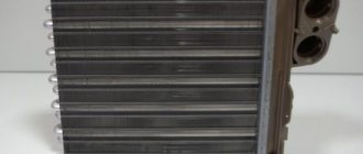
Wear of high-voltage cables
Blown fuse
Broken generator drive belt
Signs of trouble
There are several types of vehicle electrical wiring conditions in which VAZ 2109 owners are forced to look for breakdowns:
- The vehicle cannot perform its primary function, that is, it cannot drive. Either the wiring diagram of the VAZ 2109 is damaged, or one of the main components of the car is not working.
- The car can drive, but the systems sometimes start to act up or not work correctly.
If, when trying to start the engine, the driver fails, but fuel flows normally into the injector or carburetor, then most likely the problem lies in the wiring:
- If the car runs on a carburetor, then first of all you need to check the spark plugs and high-voltage wire harness. It would not be superfluous to diagnose the distributor, as well as the ignition coil. It also makes sense to check the engine compartment wiring on carburetors.
- When it comes to the injector, often the main cause of the problem is the electronic engine control system. If the system does not allow processing signals from sensors and subsequently cannot issue commands for additional components or mechanisms, then the problem must be looked for in it.
Electrical diagram of VAZ 2109 with carburetor
All carburetor “nines” use the same non-contact ignition system, built on the basis of an electronic switch and a Hall sensor.
General diagram of the contactless ignition system of the VAZ 2109
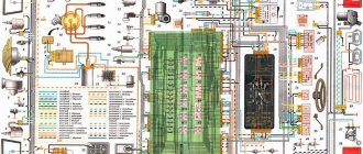
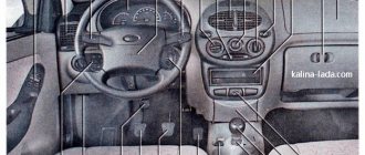
Low Panel Machine Wiring Diagram
The photo with description shows the maximum possible configuration for the “low” panel. Such machines were produced until 1996.
Wiring diagram for VAZ 2109 with a low panel and carburetor
The description of the circuit is as follows:
- Headlight.
- Electric motor for headlight glass cleaning system. An optional part, used mainly on export vehicles.
- Limit switch for powering the engine compartment lamp.
- Klaxon.
- An electric motor drives a fan installed on the radiator of the cooling system.
- Temperature indicator that provides a control signal for the electric drive of the fan impeller.
- Alternator.
- Fluid supply valve for headlight glasses. Used in conjunction with paragraph 2.
- Fluid supply valve for the glass of the fifth door.
- Fluid supply valve to the front glass.
- Spark plugs.
- Hall sensor used to distribute ignition pulses.
- Coil.
- Limit switch for reverse gear lights.
- Fluid temperature meter in the cooling system.
- Starter.
- Accumulator battery.
- A sensor that measures the fluid level in the brake booster.
- Switch that controls the ignition system.
- Sensor for determining the position of the top dead center of the piston of the first cylinder. Installed on some export VAZ 2109 with a diagnostic system. Found only on cars before 1995.
- Diagnostic block. Optional element, installed together with item 20.
- Controller for controlling the solenoid valve installed in the carburetor.
- Starter switch contact block.
- Limit switch on the carburetor.
- Economizer valve.
- Sensor signaling an emergency decrease in oil pressure.
- Washer pump drive.
- Fan impeller motor for ventilation and heating systems.
- Resistance providing additional fan speeds.
- Speed shifter.
- Windshield wiper drive.
- Cigarette lighter.
- Illumination system for levers for adjusting heater operating parameters.
- Socket for additional equipment.
- Lamp for auxiliary lighting of the engine compartment.
- Illumination system for the glove box on the instrument panel.
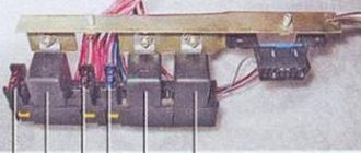
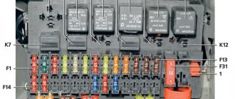
- Relay and fuse link mounting block.
- Instrument panel light switch.
- Parking brake lamp limit switch.
- Brake lamp limit switch.
- Steering column switch lever block.
- Exterior lamp switch.
- Hazard switch.
- Turn on the rear fog lamp.
- Bimetallic fog lamp fuse.
- Heated glass switch on the fifth door.
- Turn signal repeaters on the front fenders.
- Central interior lighting.
- Individual lampshade.
- Switches for backlight operation on the middle pillars.
- Ignition switching unit.
- Egnition lock.
- “Low” type instrument cluster.
- Choke limit switch on the carburetor.
- Rear lights.
- Fuel level meter in the tank.
- Heated glass.
- Rear wiper drive.
- Two lamps for room illumination.
Wiring diagram of a machine with a high panel
On the diagram, which is built on the basis of mounting block 17.3722. with the designation of elements, the maximum option for equipping a 1997 car with a “high” panel is presented.
Scheme of a VAZ 2109 with a high panel and a carburetor engine
Description of the scheme:
- 1 - headlight;
- 2 — wiper drive (optional);
- 3 — front “foglights” (optional);
- 4 — hood illumination switch;
- 5 — horn;
- 6 — fan motor on the radiator;
- 7 — fan start signal sensor;
- 8 — brake lining wear indicator on the front brakes;
- 9 - generator;
- 10 — valve with an electromagnetic drive for supplying liquid to the headlight glasses;
- 11 - a similar valve for supplying liquid to the rear window;
- 12 - similar valve for the windshield washer system;
- 13 — injection pump for washer fluid;
- 14 — oil pressure gauge;
- 15 — oil level meter in the pan;
- 16 — liquid level meter for windshield wipers;
- 17 — fuel flow meter;
- 18 — valve of the idle channel on the carburetor;
- 19 — limit switch on the carburetor;
- 20 — starter starting system;
- 21 — spark plugs and high-voltage wires;
- 22 — ignition pulse distribution sensor;
- 23 — speed meter;
- 24 — economizer valve control controller;
- 25 — diagnostic connector;
- 26 - coil;
- 27 — reverse gear limit switch;
- 28 — engine temperature meter;
- 29 — starter;
- 30 — space for installing a dead center sensor;
- 31 - switch;
- 32 - battery;
- 33 — coolant level control;
- 34 — controller for turning on the front fog lights;
- 35 — brake fluid level control;
- 36 — fuse and relay block;
- 37 — plug connector;
- 38 — door lock controller;
- 39 — lighting under the hood;
- 40 — windshield cleaning drive;
- 41 — glove box illumination;
- 42 — fan on the heater radiator;
- 43 — heater resistor;
- 44 — resistor stage switch;
- 45 — backlight of the heater control panel;
- 46 — front window drives;
- 47 — locks in the front doors;
- 48 — similar drives for rear door locks;
- 49 — lock;
- 50 — power window button on the right;
- 51 - similar to the left;
- 52 — ignition system controller;
- 53 — block of steering column switches;
- 54 — standard on-board computer;
- 55 — cigarette lighter;
- 56 — backlight brightness adjustment resistor;
- 57 — parking brake limit switch;
- 58 — limit switch warning signal about vehicle deceleration;
- 59 — glass heating indication;
- 60 — glass heating switch;
- 61 — control of the operation of the front fog lamps;
- 62 — indicator for turning on the front fog lights;
- 63 — indicator for turning on the rear fog light;
- 64 — control of the rear fog lamp;
- 65 — turn signal repeaters;
- 66 — limit switches for the backlight;
- 67 - additional fuse in the fog light circuit;
- 68 — outside light switch;
- 69 — “high” type instrument cluster;
- 70 — limit switch of the control lamp for the “suction” damper;
- 71 - alarm;
- 72 — ceiling lamp in the cabin;
- 73 — additional lampshade;
- 74 — rear lights;
- 75 — number plate illumination;
- 76 — glass cleaning system;
- 77 — nichrome heating thread;
- 78 - device for measuring the amount of fuel.
On machines produced in 1999, the block model 2114-3722010 began to be used, in which modern knife-type fuses began to be used. This device can also be found on earlier cars. The general wiring diagram does not change.
How to remove the instrument cluster
We unscrew a couple of screws securing the instrument cluster and remove it. Pull it slightly towards you, unscrew the fastening nut, and remove the speedometer cable.
Appearance of the removed plastic element
- Now you can disconnect the block with the power wires and put it aside;
- we act in exactly the same way in relation to the ignition switch, and also discard the “mass” wire from the ignition relay;
- on each side we unscrew the pair of lower screws that secure the console;
- you can disconnect the wires that supply the glove box lighting;
- unscrew the screws that hold the heater panel, after which it can be moved downward so that it does not create interference;
- unscrew the screws of the heater rod in the cabin;
- All that remains is to unscrew the last screws of the panel - the central one and the upper side ones. The panel is completely in our hands.
Wiring diagram VAZ 2109 with injector
The wiring diagram for a VAZ 2109 with an injector differs on cars depending on the year of manufacture.
Cars after 1990
Since the mid-90s, VAZ 2109 began to use engines with an injection system, which greatly changed the electrical layout of the engine compartment and instrument panel. Below is an electrical diagram of a 1999 car with an ECM type GM ISFI-2S and January 4/4.1.
Wiring diagram of VAZ 2109 with General Motors injector
The description of the circuit is as follows:
- 1 - nozzle system;
- 2 - candles;
- 3 — ignition control module;
- 4 — diagnostic connector;
- 5 — General Motors or January controller;
- 6 — connector for connecting the instrument cluster;
- 7 — main relay of the system;
- 8 — fuse for power supply wiring of the controller and ignition system module;
- 9 — protection of the speed sensor and air flow meter circuits;
- 10 — fuel supply pump power protection;
- 11 — fuel pump controller;
- 12 — engine temperature meter;
- 13 — idle system;
- 14 — detonation meter;
- 15 — tank purge system for collecting fuel vapors;
- 16 — crankshaft position meter;
- 17 — speed meter;
- 18 — air flow meter;
- 19 — lambda probe;
- 20 — throttle position angle meter;
- 21 — electric fuel pump complete with fuel level sensor;
- 22 — connection of the ignition system;
- 23 — control lamp;
- 24 — ignition switch;
- 25 - switching block;
- 26 — radiator cooling fan.
There may be cars with toxicity adjustment using a CO potentiometer. In such versions, a Bosch M1.5.4 type ECM is used, there is no converter with a lambda probe and a fuel vapor recovery system. Otherwise the wiring remains identical to that described above.
Cars after 2002
Since 2002, all VAZ 2109 began to be equipped only with engines with an injection system. The diagram shows the electrical wiring harness for the Bosch MP7.0 ECM (Euro 2 standards) on a 2003 car with a VAZ 2111 engine.
Wiring diagram of VAZ 2109 with Bosch injector
Description of the scheme:
- 1 — four nozzles;
- 2 - candles;
- 3 — ignition distribution module;
- 4 - diagnostic connector, led into the car interior;
- 5 — Bosch controller connector;
- 6 — connector for the combination of lamps and instruments;
- 7 - main switching device of the system;
- 8 — fuse-link of the main device;
- 9 — controller for controlling the parameters of the fan on the cooling radiator;
- 10 — fan controller fuse;
- 11 — fuel pump control relay;
- 12 — fuel pump wiring fuse;
- 13 — intake air flow sensor;
- 14 — throttle opening angle sensor;
- 15 — engine temperature meter;
- 16 — regulator of idle speed parameters;
- 17 — sensor for measuring detonation in cylinders;
- 18 — crankshaft position sensor;
- 19 — lambda probe;
- 20 — immobilizer control unit;
- 21 — immobilizer status indicator;
- 22 — speed sensor;
- 23 - electric motor for driving the fuel pump; in the same module there is a device for measuring the remaining fuel in the tank;
- 24 — purge valve for the gasoline vapor recovery system;
- 25 — connector of the ignition system braid;
- 26 — instrument cluster with Check Engine indicator and warning lamp;
- 27 — ignition system start relay;
- 28 - lock;
- 29 — installation and switching block;
- 30 - cooling system fan.
Vehicle handling
So, with the first two categories everything is very clear:
- Every owner understands what a loss of car control can result in.
- All identified breakdowns are immediately eliminated by repair or complete replacement of parts.
However, the wiring is not so simple. For some reason, everyone is accustomed to thinking that underhood wiring does not pose any danger. But this is a very big misconception.
The short circuit and ignition of live wires threatens that the car may simply burn out, explode, etc. And all this can happen both while parked and while driving.
Underhood wiring includes the following categories:
- Ignition system wires.
- Lighting systems, side lights.
- Connection system for sensors and control unit.
- Wires that are responsible for the operation of the electric motor of the radiator, washer, windows, and wiper.
If the wiring is in good condition, all current-carrying parts are insulated and qualitatively fixed in the engine compartment, taking into account all the necessary physical and temperature indicators of the internal combustion engine.
However, during vehicle operation, fastenings may deteriorate, which will entail:
- Loose contact.
- Destruction of insulation upon contact with hot surfaces of the engine and commutator.
- Formation of abrasions and exposure of wire cores.
- Oxidation of contact connections due to which the “mass” may disappear.
Most owners of the VAZ-2109, as well as other modifications of the domestic automobile industry, independently repair damage in which electrical tape is a direct participant. However, this is only a temporary solution and is not suitable for permanent operation of the machine. If there are problems with the wiring, the best way out of the situation is to completely replace it. According to the instructions, the harnesses must be laid in a corrugation, which is not the case on most machines.
Replacing wiring VAZ 2109
When performing any work, you must pay attention to the color markings of the wires, which must match those indicated in the diagram.
For numerous repairs, the wiring of old machines can be replaced using cables with any color of insulation. Therefore, if you find wires of unknown designation in the electrical circuit of the VAZ 2109, they must be called with a tester. For a more detailed analysis, it is recommended to use an interactive wiring diagram, which can be easily found on the Internet.
Changing the wiring on a car can be done entirely or in parts.
For a complete replacement with your own hands you need:
- Remove the engine compartment harness, starting from the right headlight connector and moving towards the switch and fuse box terminals.
- Remove the rear wiring harness, starting with the rear lights and the module in the fuel tank.
- Remove the plastic cover of the instrument panel and dismantle the wiring harnesses.
The procedure for repairing wiring on a VAZ 2109 is presented in a video from the AVTO LIVE channel.
All wiring on the VAZ 2109 converges on the fuse block. When removing, it is advisable to take photographs of cable routing and connector connections. This will be useful when installing new wires, which may differ in length and connectors from the ones used. During installation, it is necessary to carefully clean and tightly install the ground wires. If the contact is poor, the switching on of the circuits will be accompanied by a click and disconnection of the circuit under test or the entire electrical system. Before final assembly of the interior, you should check the functionality of all electrical components. It is recommended to carry out monitoring both by switching on individual circuits and jointly.
Useful tips
Following simple recommendations will extend the life of the wiring and simplify the life of the car owner.
It is worth periodically looking under the hood of the car and checking the condition of the insulation and connectors. If broken wires are detected, their further destruction and short circuit should be prevented. This can be done using electrical tape or heat shrink. If the wire is literally hanging by a thread, then it is necessary to strip the ends, tin and solder. Then it is good to isolate the connection. Poor contact in the connectors must be eliminated. You can use pliers. Clean oxidized surfaces with a special product, WD-40 can be used. A good engine crankcase protection protects the wires from moisture, so it is necessary. Oil-contaminated insulation deteriorates faster. The use of corrugation to protect against this would be useful. It is better to replace the old wiring, since in this case the risk increases.
What's inside the cabin
Replacing the power unit will also require replacing the interior wiring.
Many owners combine this process with replacing the instrument panel with a modern one:
- the “high” panel from the VAZ 21099 fits without modification;
- The “LUX” panel from the VAZ 2114 model is suitable with minor modifications.
Tip: there are a lot of videos on the Internet that describe in detail the process of finalizing the panel. Read them all carefully before starting work on your car.
Search algorithm
You need to start with something simple - determine whether an electrical impulse is supplied to the spark plugs:
- Remove the tip from the first candle;
- We expose his contact;
- We bring it to the metal part (possibly to the cylinder block) at a distance of 4-5 mm;
- We run the starter for a couple of seconds;
- Let's see if there is a spark.
Advice: in this way we divide the troubleshooting. If a spark is supplied to the spark plugs, then it is unlikely that all 4 have failed. This means that the problem of failure should be sought in the power system.
If there is no spark, then we continue to search for a malfunction in the ignition system.
To do this, we carry out a spark test:
- We remove the central wire coming from the coil from the distributor cover (ignition distributor);
- We bring it again to the metal part of the engine;
- We turn on the starter and watch to see if an electric discharge passes through.
Advice: If there is no spark, then further troubleshooting should be carried out using diagnostic tools. Moreover, every owner who independently maintains the car should have such devices. Moreover, their price is low.
The simplest but effective devices have long been produced for motorists. With their help, you can diagnose a fairly large contingent of cars from the domestic automobile industry:
- A family of VAZ cars (models 2108, 2109, 2110) that have the same connectors for electronic switches;
- Cars of Ukrainian origin (Tavria and ZAZ);
- OKA cars, etc.
Of course, with their help it is impossible to determine whether the VAZ 2109 engine compartment wiring needs to be replaced, but they are able to detect a failed electronic unit or electrical circuit. Their functions include:
- Checking the functionality of the ignition coil;
- Checking the Hall sensor;
- Checking the operation of the ignition switch and contact group;
- Checking the ignition relay.
It is enough to connect the MD-1 device instead of the standard switch and turn on the ignition (without starting the engine). With the help of LED lamps built into the housing we will see:
- The ignition relay and lock are operational if the “P” LED lights up;
- The primary winding is in working condition if the “K” LED lights up;
- We turn on the starter for 1-2 seconds and monitor the LED “D” - if it starts blinking, then the Hall sensor is operational.
Conclusions: knowledge of the operating features of the VAZ-2109 car systems, and the simplest diagnostic instruments will help you quickly find the failure problem and also quickly eliminate it.
voice
Article rating
How the injector wiring should work, how to connect it yourself
When deciding to make major modifications to their car, or restoring it after serious breakdowns, many motorists are faced with the need to replace the wiring. In the design of any car, it is possible to replace either the under-hood wires, mainly coming from the injector, or the interior electronics that ensure the operation of application devices. In today’s article we will look at the features of repairing and replacing both types of wiring, taking VAZ cars as an example. Interesting? Then be sure to read the article below to the end.
What elements does the diagram include?
The main components of the electrical circuit in the VAZ 2108:
Full diagram of the G8 equipment
In general, the electrical circuit consists of many devices, and it doesn’t matter whether we are talking about an injector or a carburetor, whether the car is equipped with a high tidy or a low panel.
The main components of any electrical system, without which engine operation is impossible, are the following:
1. Generator device connection diagram
2. Contactless ignition system