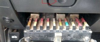
Purpose of the VAZ 2107 relay
| Relay number | Relay purpose |
| R1 | Heated rear window relay |
| R2 | Relay for headlight cleaners and washers (wiper relay) |
| R3 | Signal relay. If there are two signals, then there is a relay. If there is only one signal, a jumper |
| R4 | VAZ 2107 cooling system fan relay. Or a jumper if the car is fuel-injected |
| R5 | High beam relay |
| R6 | Low beam relay |
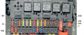
On VAZ 2107 cars with an injection engine, several more relays and fuses can be found under the glove compartment. They look like this:
Relay and fuse box in the center console
Diagram of the relay and fuse box in the central instrument panel
Designation and numbering in the block
Location of the relay and fuse box in the console
Circuit breakers
| No. prev. | Ampere | Purpose |
| 1 | 15 A | ignition module, controller |
| 2 | 15 A | canister purge valve, vehicle speed sensor, oxygen sensor (heating) and air flow sensor |
| 3 | 15 A | fuel pump, injectors |
Relay
| Relay no. | vendor code | Purpose |
| 4 | electric fan | |
| 5 | electric fuel pump | |
| 6 | ignition |
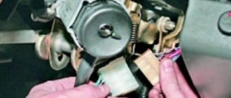
Relay for turn signals, alarm and ignition relay for VAZ 2107
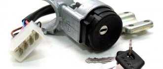
The turn signal and ignition relay is located behind the instrument panel. To replace or check the relay, you need to remove the instrument panel and you can see it behind it:
| Relay number | Relay purpose |
| R4 | Ignition relay VAZ 2107 |
| R5 | Relay for alarm and turn signals VAZ 2107 |
Wiring diagram for the ignition switch on the VAZ-2108, 2109 and 21099
Wiring diagram for the ignition switch on the old-style VAZ-2108, 2109 and 21099 with an unloading relay.
Pinout of the VAZ-2109 ignition switch with unloading relay:
- comes +12V in position I, II, III (parking)
- comes +12V in position I, II, III (parking)
- comes +12V in position III (parking)
- position I, +12V goes out after turning on the ignition (contact 15/2), disappears at start (II);
- position I, +12V goes to the starter (pin 50);
- position I, +12V goes away after turning on the ignition (pin 15), does not disappear when starting II;
- +12V comes from the battery (pin 30);
- comes +12V constantly.
Wiring diagram for the ignition switch on the VAZ-2108, 2109 and 21099 of the new model, without a relay.
Pinout of the new VAZ-2109 ignition switch:
- comes +12V constantly
- comes +12V constantly
- +12V arrives after turning on the ignition (pin 15), does not disappear when starting II;
- +12V arrives after turning on the ignition (contact 15/2), disappears at start (II);
- position I, +12V goes to the starter (pin 50);
- +12V arrives after turning on the ignition (pin 15), does not disappear when starting II;
- +12V comes from the battery (pin 30);
- comes +12V constantly.
Photo 1, pinout of the new VAZ 2109 ignition switch
Photo 2, pinout of the new VAZ 2109 ignition switch
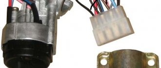
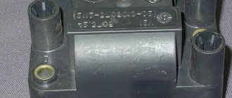
Design and operating principle
When an electric current passes through the coil, an electromagnetic field is created, under the influence of which the armature moves inside the core. When the power is cut off, the field disappears and the armature begins to move freely along the core.
The ignition relay includes the following components:
- Electromagnet;
- Anchor;
- Return spring;
- Contacts;
- A pair of windings.
The electromagnet, in turn, includes two coils in its design.
Coil type
Peculiarities
It is connected to the ignition relay housing, as well as the control output
The retractor coil is connected to the motor contact as well as the control terminal
Device location
The operating principle of the node is based on the following:
- When voltage is applied to the control contact, electric current begins to flow through the coils. This leads to the appearance of an electromagnetic field, under the influence of which the armature moves, compressing the return spring;
- The armature also moves the bendix, then the rod, which closes the contacts connecting the battery with the starter motor;
- When the contacts are closed, a plus is supplied at the output of the retractor coil, which moves to the motor output. So the current stops passing through it - the magnetic field disappears, but the armature remains in the retracted position due to the influence of the magnetic field from the holding coil;
- The armature returns to its original position after the engine is started and the power is turned off, which occurs under the action of the return spring;
- In this case, the contacts open, the bendix is disengaged;
- The contacts of the retractor relay are bolts that are installed in the textolite cover, as well as plates (can be round or rectangular). They close the bolts when the armature moves.
Coil type
Peculiarities
Device location
Ignition switch consumers. This article will be useful to those who want to upgrade the ignition switch (for example, start the engine with a button) or are experiencing problems with the lock. Only the electrical part of the lock is described. We will consider the ignition switch in the VAZ-2114 version. It, unlike the VAZ-2108 lock, works in conjunction with the ignition relay.
0 - all consumers are turned off (used extremely rarely) 1 - ignition on 2 - starter on 3 - parking (key removed from the lock) Voltage from the battery is always supplied to contacts 7 (pink) and 8 (brown) of the lock. These wires are connected in parallel and connected in the mounting block. The division into two wires was apparently done for reliability, or it may have developed historically - these wires can be replaced with one wire.
Load of wires and contacts of the lock
The brown and blue-black wires power the ignition relay, power window relay coils and heated seat relays, carburetor electronics, on-board computer and instrument panel, lamp monitoring relays, reverse lamps, front wiper, and also provide a signal to the ECU, immobilizer and on-board computer .
The black wire (pin 2) powers the “dimensions”, the engine compartment lamp, the relay coils for the fog lights and high beams, the license plate illumination, the on-board computer, the button and instrument panel illumination.
The blue wire (pin 4) is the most loaded. It powers the heater fan, rear fog lights, rear window and headlight wipers, relay coils for headlight wipers and heated rear window, low and high beams, and glove compartment lighting. This wire is disconnected when the starter is turned on (position 2 of the lock).
Pink connects the black, blue and red wires, therefore the load on it is summed up.
The armature is also moved by the bendix, and later by the rod, which closes the contacts that the battery closes with the starter motor. When the contacts close to the terminal of the retracting winding, which goes to the motor terminal, a plus is applied and the current stops passing through it - the magnetic field disappears, but the armature still remains in the retracted state under the influence of the magnetic field of the holding winding.
The armature returns to its original position after starting the engine and turning off the power by the action of the return spring, opening the contacts and disengaging the bendix. The contacts of the pull-in relay are bolts that are fixed in a textolite cover and rectangular or round plates that close the bolts when the armature moves.
Coil type
Peculiarities
Where is the VAZ 2109 starter relay located - Car lover's blog
The fuse mounting block is a box with installed fuse links and protective parts. This is necessary to insure against voltage drops in the on-board network caused by short circuits or damage to devices. Our editors have collected information about locating the VAZ 2114 starter relay and other important inserts to make the search as easy as possible.
On the fourteenth model with an 8-valve engine, two power supplies are installed. The first is located inside the engine compartment. More specifically, the block is located under the windshield on the right side in the direction of travel of the car. Externally, the device looks like a black box with a plastic lid.
The indoor unit is located in the cabin, under the feet of the front passenger on the left. The side part of the instrument panel is made in the form of an inspection hatch that provides access to the protective elements.
Starter protection is designed to protect the circuit of the corresponding unit from overload or short circuit. In appearance, it is a standard four-pin device suspended on a bolt inside the engine compartment.
In this case, the injector or carburetor is designed in the same way - the block is suspended independently. The exact location of the element is impossible to describe. Thanks to the “special” approach of the designers, the hitch may differ depending on the year of manufacture. Therefore, it is best to start your search from the starter terminals and move along the wires to the device itself.
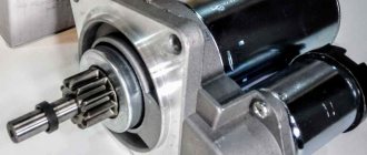
The starter retractor is an electromechanical device installed directly inside the unit housing. The part is responsible for the clutch of the engine flywheel with the electric motor gear.
The search is carried out by visual inspection. The retractor is located in the same housing as the main unit and has two large contacts coming from the ignition switch and the battery.
The starter interlock device is a separate unit that prevents the rotation of the electric motor armature after starting the power unit of the machine. Thanks to a well-thought-out design, after turning the ignition key, a group of contacts is closed, passing current to the starter. After the motor spins up and the circuit opens, the diode closes and the excited windings are de-energized.
The exact location of the block differs depending on the year of manufacture. The type of power plant also affects the installation.
The main relay is designed to start the vehicle's power plant. This unit is powered through the ignition switch and supplies voltage to the injectors, spark plugs, ignition module and fuel pump. Thus, if the unit breaks down, all the necessary electrics are de-energized and the car will not start.
On the VAZ 2114 the block is located near the ECU under the dashboard on the passenger side. There is also a fuel pump protection element nearby.
The ignition relay, by definition, is another name for the GR. The insert is located inside the cabin on the right side of the dashboard. To access the insert, it is necessary to dismantle the protective plastic plate where the bolt is installed.
The intended purpose of the device is to close the circuit that triggers the start of the power plant.
This unit is responsible for charging the battery and the amount of charge supplied. The part is located on the back wall of the generator itself. To prevent getting wet, the element is covered with a plastic cover. Externally, the device is a black tablet with two graphite brushes.
Another name is voltage regulator. This was deliberately thought out, since the design performs two functions at once - protective and regulating.
The fuel pump fuse together with the corresponding element is located inside the cabin unit at the feet of the front passenger. The panel itself is equipped with three inserts, the first of which is the necessary element. The corresponding fuse is located nearby. In the corresponding photos you can see the exact position of the part against the general background.
The price of this unit starts from 100 rubles. A fuse can be bought for 10-15 rubles.
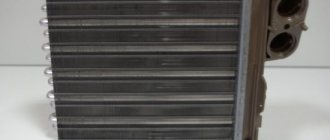
This element is necessary for thermal regulation of the machine engine. When driving at low speed, the motor overheats, which requires forced activation of the cooling fan. The detail is responsible for exactly this.
The insert is also located inside the passenger compartment at the feet of the front passenger. According to the factory instructions, the required part is installed first on the left. However, the exact location and order may vary depending on the year of manufacture.
The windshield wiper or wiper protection is located under the hood inside the main unit. The part is responsible for the operation of the breaker and the supply of power to the mechanism drive. According to the standard instructions, the insert is marked K3.
Heater relay
In fact, this is an independent element of the electrical network, responsible for the operation of the stove fan. On standard designs, the regulator can set three positions - minimum, medium and maximum airflow.
The exact location is determined by the tidy - exactly in the center of the panel, under the heater.
Turns relay
An element included in the instruments of the main unit near the left front pillar of the car. The insert is responsible for sending a signal to the turn signal switches and an emergency signal. In the event of a failure, the lamps may light continuously or not light up.
The rear fog light protector is designed to protect the circuit from overload or short circuit. Usually displayed inside the cabin near the light switch. The location of the insert on each car may differ, since the VAZ 2114 does not have lights in the factory configuration. This circumstance provokes buyers to install the equipment themselves or order installation when purchasing from an authorized dealer.
Author of the material: Borisov Maxim
Relay box in the center console
Diagram of an additional relay block on the left side of the center console
Designation and numbering of relays and control units in the center console
Location of the relay box in the car
Designations
| Element no. | vendor code | Purpose |
| 1 | Central locking control unit | |
| 2 | Immobilizer block | |
| 3 | Rear fog lamp relay |
See also
Model range VAZ 2110
Is the mounting block with relays and fuses conveniently located?
| Rate the usefulness of the material: useful useless Thank you! Your vote has been counted! | Technical Department AG About the authors |
Additionally
| • All Vaz models with a galvanized body • What people ask about Vaz cars • Vaz dismantling shops in your city • Discuss the topic on the forum • See other instructions • on the forum: Auto repair and maintenance | Save this page! |
Additional block
It is located under the center console and is covered with a lid. One part is accessible from the right side.
Scheme
Designation
- 15A - Ignition module, controller
- 15A - Canister purge valve, vehicle speed sensor, oxygen concentration sensor (heating), air flow sensor
- 15A - fuel pump, fuel pump fuse, injectors
- Electric fan relay
- Fuel pump relay
- Main relay (ignition relay)
The other part is on the left side of the console:
Scheme
Decoding
- Central locking control unit
- Immobilizer block
- Relay for turning on rear fog lights.
This is interesting: How to check the generator on a VAZ