Causes of tachometer malfunction
Most often, a sign of a broken meter is “inappropriate” needle behavior. If it freezes or twitches, you need to look for the source of the problem. In this case, it is worth repairing or replacing the device.
If the tachometer does not work, the “leading” functions of the car do not suffer. But experienced car owners warn that incorrect readings from the device do not allow timely identification of a problem with the engine. If you ignore this, there is a risk of facing the need for repairs or even installation of a new power unit.
If the tachometer does not work, the reasons may be the installation of silicone prototypes of the factory ignition wiring (the arrow twitches). This happens due to a change in the electric current pulse. To diagnose the problem, lower the resistor value on the transmission board. Also check the speed sensor - it may be transmitting erroneous data. And, of course, there is always the possibility of failure of the device itself.
Arrangement
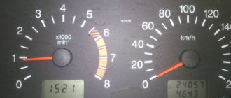
So, what can you see on the instrument panel in this car? The combination consists of several components:
antifreeze temperature indicator in Celsius; tachometer - number of revolutions of the power unit; right and left turn indicators; speedometer - vehicle speed; fuel reserve - the volume of fuel in the tank; image of a gas station - a signal about the need to refuel; control indicator for starting dimensions; brake fluid level indicator; starting high beam headlights; knob for adjusting the clock; display with total and daily mileage; alarm control indicator; clock screen; battery charge level; check engine - indicates an engine malfunction;
indicator indicating the handbrake is engaged; oil pressure level; choke light - only available on carburetor engines.
The tachometer does not work on the VAZ 2112
During the production of the VAZ-2112 passenger car (1999-2008), it was equipped with five models of electronically controlled engines, and there were only two instrument clusters.
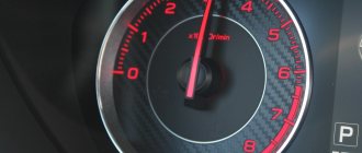
One of them was installed on the front panel, the old model, and the second, on the front panel of the new model. In appearance, they differed in the location of the instruments. On the old combination, when looking from left to right, the first instrument was the temperature indicator, and the second was the tachometer. On the new combination, the tachometer is in the extreme left position. The duties of the tachometer include providing the driver with readings of the engine crankshaft speed. The movement of the pointer along the tachometer scale is ensured by a stepper motor due to the rotation of the armature shaft on which the pointer is attached. The angle of rotation of the arrow will depend on the frequency with which the voltage pulses occur in the ignition system. Indeed, on all VAZ-2112 engines, during one revolution of the crankshaft, the spark on the spark plugs jumps twice, which corresponds to two pulses in the ignition system circuit. But the stepper motor will not work from these pulses, so the wire from the ignition module goes to the ECM controller (electronic engine management system), where it is converted, and then through another pin the control signal is sent along the wire to the tachometer. In addition to this wire, the + from the ignition switch comes to the tachometer and one of the wires goes to ground.
If a malfunction occurs that leads to a failure of the tachometer, you will have to look for it in the three devices mentioned above: the ignition system, the ECM controller, the instrument cluster, as well as in the wires and plug connectors that form the electrical circuit for the tachometer. But, not a single device, including the tachometer, from the combination is supplied as spare parts, and in case of failure you will not be able to purchase it. This means that the entire instrument cluster will have to be changed, since it cannot be repaired.
Rarely, but there are still cases of oxidation of the contacts in the connector blocks of the instrument cluster, which is why the tachometer refuses to work. Any driver can check the condition of the plugs if desired. You just need to know in which block the required plug numbers are located. On old front panels of a VAZ-2112 car, you will have to disconnect the white block X1 of the instrument cluster and check plugs No. 1 (ground), No. 2 (low-voltage tachometer input), No. 3 (high-voltage tachometer input). And on the new front panels, disconnect block X and check plug No. 30.
Examination
It is better to test the component components of the engine speed counting system in order of priority. This will help to quickly identify the malfunction and conduct an additional examination of the condition of each element.
Before checking the electrical circuit and its parts, you should make sure that the fuel injection system is working. The serviceability of the gas distribution mechanism also affects the performance of the tachometer. Only after checking these components can we assume that the tachometer circuit is not working.
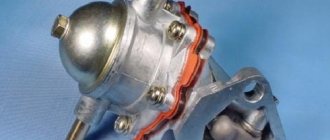
DPKV
This device is located near the machine's generator pulley. You can check its operation using a multimeter. To do this you need:
- Set the multimeter to resistance measurement mode.
- Disconnect the sensor power supply connector.
- Connect the red control probe of the tester to terminal “1”.
- Connect the black measuring probe to terminal “2”.
- Crank the engine with the starter.
When open, the device will show a resistance of up to 550–750 Ohms. If the tester does not measure the operating resistance of the sensor, you will have to dismantle it. To do this, you will need to unscrew one nut that secures the element. Very often, metal shavings stick to the magnetic sensor and interfere with the opening. If chips have accumulated on the rod, they must be removed, the body must be cleaned with a solvent and the resistance measurement must be repeated.
After checking the DPKV, you need to check the integrity of the wiring that powers the sensor and transmits pulse signals to the control unit. It is necessary to inspect the wires and check the integrity of the insulation. You will also have to clean both halves of the connecting plug with solvent.
Ignition module
This device is most often prone to breakdowns. This happens due to a short circuit to ground. The check is carried out with the engine running. During operation of the power unit, it is necessary to remove the power wires from the spark plugs one by one. After this, you need to direct the end of each wire towards the engine block, but without touching it. A spark should appear from the end of each wire. It should be blue. If the spark is yellow or there is no spark at all, the module and wires will have to be ringed.
The wires can be tested with a multimeter only to check the integrity of the cores. It is not possible to determine an insulation breakdown in this way. It is better to replace all suspicious elements with new ones. Often, owners replace standard high-voltage wires with modern silicone analogues; this should not be done. The electrical resistance of such wires is very high; it does not allow the spark of the required discharge to pass through. It is also worth carefully inspecting the caps that are placed on the candles. Parts with poor contact or external defects must be replaced.
Before checking the module, you need to test the wiring that powers this device. To do this, you need to disconnect the plug. Next, you will need a multimeter in DC voltage measurement mode.
- Connect the red measuring probe to terminal “1”.
- Connect the black measuring probe to terminal “3”.
- Turn on the ignition.
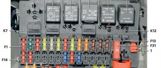
The tester should show a voltage of 12 volts or equal to the battery voltage. If there is no voltage at all, then you need to check the integrity of the fuse responsible for the ignition module. It is located under the trim on the right side under the instrument panel, the very first one on the hood side. Has a rating of 15 amps.
If voltage is supplied to the module, then it is necessary to check each coil of this assembly.
- The primary windings are checked for the presence of operating resistance. To do this, you need to switch the multimeter to resistance measurement mode. Next, you need to connect the red test lead to pin 1 of the power wire going to the first cylinder, and the black test lead to pin 4 of the cylinder. The operating resistance must be at least 0.5 Ohm.
- The second primary winding is checked in the same way, only at terminals 2 and 3.
Next, the secondary winding is checked. To do this you need:
- Connect the red measuring probe to terminal “1” on the module socket.
- Connect the black measuring probe to terminal “3”.
- The operating resistance should be 0.5 Ohm.
The third check is the most important. It is carried out to test for the presence of a short circuit.
- The red test probe is connected to the module's connecting socket.
- The black test probe is connected to the device body.
- A working module should not show resistance. If it is, even the most minimal, then the device will have to be replaced.
If the module has fully passed the test, it must be inspected. Any cracks in the housing, even the most minor ones, can create a ground fault during operation in wet weather. Such deformations cannot be eliminated; the unit will have to be replaced with a similar one. You also need to clean the sockets of the high-voltage wires going to the spark plugs.
Fuse
Very often the tachometer does not work due to a fuse problem. If the instrument panel does not work at all and there is no backlight, then we can assume that fuse “F9” has failed. It must be removed and checked using a tester. The multimeter is switched to continuity mode, both test leads are connected to the fuse contacts. The absence of a buzzer will indicate a malfunction of the protective element. It will have to be replaced with a similar device rated 10 amps.
You also need to check the fuse socket. Clean any dirt, oxidation, carbon deposits with alcohol. Bend the contacts with a screwdriver.
Next, the electrical voltage coming to the fuse is checked. This requires:
- Switch the multimeter to voltmeter mode to measure DC voltage.
- Connect the red test lead to the fuse output.
- Connect the black test lead to ground.
- Turn on the ignition.
The voltmeter should show a voltage identical to the battery charge.
Receiver block
If the previously described checks did not bring results, and all the elements are in good order, then you need to test the tachometer itself. A simple check is to reset the odometer. After resetting, you need to hold down the odometer button and turn on the ignition. The tachometer and speedometer needles should deviate to the maximum position and return back. If the tachometer does not respond to the voltage supply, you will have to dismantle the dashboard and remove the device. To do this, you need to unscrew the 4 screws of the cladding in front of the protective glass and dismantle it. Next, remove 4 more screws holding the instrument panel itself. After dismantling, you need to pull the block towards you.
Electrical power is supplied to the tachometer through a yellow (sometimes white) connector. “+” terminal number “8” is the very first in the bottom row. To check the power supply, you must:
- Switch the tester to DC voltage measurement mode.
- Disconnect the plug.
- Connect the red probe to pin “8” of the incoming power cable.
- Connect the black probe to ground.
With the ignition on, the voltmeter should show a voltage of up to 12 volts. If there are no readings, then you should check the ignition switch terminal.
Next, terminal “2” of the receiver unit itself is checked. She is the very first one in the top row. Responsible for power supply with pulsed current. To check it, you need to run a test wire from the “+” terminal of the battery. The second end of the wire must be abruptly connected to terminal “2” several times. The tachometer needle should respond to the simulated impulses by deflecting at a certain angle. If there is no deviation, then the reason lies in the receiver itself.
It needs to be inspected visually for oxidation and broken tracks. A big problem with such receivers is microcracks in the solder. You should carefully inspect all connections and eliminate any defects found. Then repeat the check again.
If the receiver unit is working properly, power is supplied from the ignition and there is a reaction from the arrow to simulated pulses, then the problem lies in the ground terminal. It is the very first one, located in the corner between the rows of plugs. Necessary:
- Set the tester to voltmeter mode.
- Connect the red test probe to terminal “2” of the incoming cable plug.
- Connect the black probe to terminal “1” of the same plug.
- Turn on the ignition.
If there are no readings, then it is worth connecting the black control probe to ground in another place. The presence of data will indicate a break in the ground line. It can be pulled through using a jumper and pre-fixed with a bolted connection in the engine compartment.
Featured Posts
Anatoly-
Car VAZ21124 Y7.2 tachometer does not work. What I did was check all the electrical circuits connected to the tachometer, throw in a new electronic unit. I changed the instrument panel, the tachometer does not work. I tried and tossed the EB. Bosh7.9.7 worked, I return Ya7.2 does not work. The guy says that the tachometer worked before. Who has any thoughts, what is the ambush?
Xander ROTTEN DICK
Open the ECU and ring 8 pins... no other thoughts.
romelo
Did you do something with her, or did he already arrive like this? You need to ring with a control or an oscilloscope, starting from the block; if there is no signal from the block, then it is already clear that the block. If repair is unrealistic, then you can somehow hook it up to the injectors or coil.
Softer
Car VAZ21124 Y7.2 tachometer does not work. What I did was check all the electrical circuits connected to the tachometer, throw in a new electronic unit. I changed the instrument panel, the tachometer does not work. I tried and tossed the EB. Bosh7.9.7 worked, I return Ya7.2 does not work. The guy says that the tachometer worked before. Who has any thoughts, what is the ambush?
The tachometer output is controlled by a key in the block to ground. And pulled up to +12V through a 4.7 kOhm resistor.
Check with a DIGITAL multimeter with the ignition on to see if there is pull-up voltage at the output.
Modified on July 3, 2010 by Softer
Anatoly-
I didn’t do anything with the block; the guy already arrived with one. The fact is that I bought a completely new EB from the store. I threw it in and the tachometer still doesn't work. I took the instrument panel from another car, it doesn’t work, I put the original instrument panel on another car, it works. And it works with BOSCH7.9.7. That is, there is no point in ringing the circuits inside the block. Maybe something is wrong with EEPROM? Or is it a bug?
andreikl
You might want to try attaching an external +12V resistor to the tachometer wire so as not to damage the unit. By the way, the tachometer wire can connect to 2 points on the tidy. Look where the tachometer wire went on the car from which the tidy worked
Softer
2 inputs - this is in old devices. Low voltage – the one for control units. And high-voltage - connected directly to the ignition coil.
masters41
Or maybe hang an external generator from the output of the unit to check the wiring and panel?
- 4 months later...
DGON-S
Check the battery charge, I had an increased charge of 15.5v. The tachometer turned off two seconds after starting.
Precautionary measures
When performing dashboard repairs, you should follow some rules:
- You can change fuses only with the ignition off;
- monitoring of devices must be carried out as carefully as possible to avoid short circuits;
- Damaged elements should be soldered using a device with minimal power and a thin nozzle;
- You need to remove and fix the shield very carefully so as not to inadvertently damage the fastenings.
[custom_ads_shortcode1]
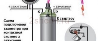
VAZ tachometer connection diagram
The first car from the Zhiguli family equipped with a tachometer was the VAZ 2103. Neither 2101 nor 2102 had such a device. The tachometer is used to measure the crankshaft speed. It is a revolution counter, showing their number by deflecting the scale needle to a certain angle. The tachometer is also indispensable when setting up the carburetor - its indicators are taken into account when adjusting the idle speed and the quality of the fuel mixture.
Connection diagram for tachometer VAZ-2108 and 2109
Let us immediately note that the fuel supply system – injector or carburetor – does not play a special role here. As you know, currently the most common are cars with the following engine types: gasoline or diesel. Depending on this, the tachometer is selected, unless, of course, it comes in the stock version. The thing is that on gasoline engines the tachometer reads data from the ignition coil, or rather, the impulses that arise here. However, the design of diesel power plants does not provide for this unit. Accordingly, here the tachometer reads pulses not from the ignition coil (for lack of one), but from the generator.
The first two wires (12-volt and Signal) are to contacts “B” and “K” of the ignition coil, respectively. All that remains is to secure the mass in any convenient place.
What exactly needs to be done
Check the cap on each of the wires: if the copper is burnt, clean it with ASIDOL, ammonia and ordinary chalk. The taps on the module should also be cleaned. For better protection, you can apply lithium grease (Litol-24). Here's what you can't do:
- Check for the presence of a spark by bringing a “grounded conductor” to the tap;
- Connect the “+” terminal removed from the battery to ground with the engine running;
- Apply voltage “+12” to any of the module contacts.
How to perform an express check: the key is at “0”, then we measure the resistance between taps 2-3, 1-4. Both values must match. By the way, the multimeter must be a dial gauge.
Schematic diagram of the tachometer electronics
Connecting modern electronic tachometers:
Read also: Mazda 0w20 skyactiv oil
A tachometer designed for a 4-cylinder engine cannot be installed on another, because the readings will be false. Therefore, select a tachometer in accordance with the make of the car and the number of cylinders.
Why the tachometer does not work on VAZ cars
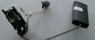
Our cars are mainly equipped with mechanical odometers and speedometers (Audi, for example, have an electronic analogue), so there is a risk of the cable breaking. This breakdown is accompanied by a specific noise in the panel area. In this case, the device produces erroneous information.
In this case, you need to check the performance of the speed sensor by measuring the voltage. If everything is in order with the tested parameter, proceed to diagnosing the device itself.
In many cases, mechanical problems occur.
Try to disassemble the drive and deal with the problem yourself. An alternative option is to contact a car service center.
If there is no voltage, examine the electrical connections:
- terminals;
- pads;
- wires.
New car models often have built-in electronic meters that receive data from the speed sensor of the box. In this case, the cause of the breakdown may lie directly in the odometer (if so, a complete replacement of the “tidy” is necessary) or in the sensor.
On a VAZ, which is equipped with a carburetor engine, three wires are connected to the tachometer. One of them is connected to the coil terminal, and the others are connected to the power supply (“+” and “-”). In this case, to identify the source of the problem, the terminals are switched from the device to the battery. Next, start the engine. If the device does not work, the source of the malfunction must be sought in the ignition or in the device itself. If operation is correct, proceed to wiring diagnostics.
The injectors have four wires that go:
- the first - to the ECU;
- the second - to the crankshaft position sensor;
- the third and fourth - to nutrition.
Only computer testing is possible here.
A person can only inspect and replace parts - it will not be possible to qualitatively analyze the operation of the system.
VAZ-2110 tachometer connection diagram
- tachometer VAZ;
- trip computer;
- ECM;
- crankshaft position sensor;
- ignition module.
Tachometer VAZ 2110 - with four outputs: if it is on a car with injection, it is connected not to the ignition (input 2), but to the ECM controller with an additional output provided for this (input 1) - and in this case it reads the number of revolution pulses directly from the controller. It receives a signal about the position of the shaft.
Start with the fuse
So, let's take a closer look at the situation when the instrument panel on a VAZ-2110 does not work (partially or completely), as well as possible causes and troubleshooting options. To do this, we first list the instruments and indicators available there:
- tachometer;
- speedometer;
- fuel level and coolant temperature indicators;
- 18 lamps – 6 panel lights and 12 control lamps;
- reserve socket for control lamp;
- 2 terminals for connecting wiring.
Regarding the latter, I would like to give a brief explanation on how to distinguish them on electrical circuits. In particular, the white block is designated as X1, the red block, respectively, as X2.
Another rather important point: VAZ-2110 cars can have one of two dashboard options. If it is an old model, then all devices are placed symmetrically. At the same time, the “Europanel”, in addition to the fact that it is more beautiful purely visually, is also distinguished by its coolant temperature and fuel level indicators shifted to the right.
Tachometer malfunctions - finding the cause yourself
Use a multimeter and know the wiring diagram of your car.
It is better to take measurements with a multimeter. To operate, you must know how to use it. The “tester” makes it possible to measure power, “ground” and “ring” the main wire for a break.
Power measurements are carried out in DC mode (select a range within 20 Volts). In this case, “-” is always present, “+” appears after the ignition is activated. Ideally, the signal wire shows pulses while the crankshaft is rotating.
Breaks are looked for by setting the ohmmeter function on the multimeter. If the problem is in the contacts, move the harness/connector.
Is the tachometer not working properly? Sometimes this is due to design defects in the car. For example, it happens like this: the operation of a generator, when the current on the excitation winding is regulated by alternating voltage, is accompanied by “vibration” of the needle (typical of old VAZ cars). This defect can be corrected by changing the connection diagram or updating the dashboard.
Classification by operating principle
- Mechanical or electromechanical tachometers with direct drive. The revolutions are transmitted to the dial indicator through a flexible shaft, which, through a worm gear, receives rotation directly from the crankshaft or one of the transmission shafts. The operating principle of the indicator is based on the phenomenon of eddy current induction. The operation and design of a magnetic tachometer are extremely similar to the operating principle of a car speedometer. In modern cars, a similar tachometer design is not used.
- Electric machine. A distinctive feature is the connection to a generator. It is used primarily on diesel engines, but for the purpose of unification, a device of this type can also be used on gasoline engines.
- Electronic. The signal can be taken either from the ignition system or directly from the computer. Installed on gasoline and diesel internal combustion engines.
Design and principle of operation
Main components of electric machine and electronic tachometers:
- measuring unit, or signal converter. It can be based on elements of analog circuitry or built using special microcircuits;
- display unit with analogue or digital display of the number of revolutions;
- auxiliary elements.
The operation of electronic tachometers is based on the conversion of individual signals or pulses captured from the computer, ignition system or generator into a signal “understandable” for the display unit.
Connection diagram
When looking for the reason why the tachometer does not work, it is first of all important to understand the connection diagram and the type of signal. There are 3 typical connection schemes:
- to a contactless ignition system (the tachometer wire is connected to the primary circuit of the ignition coil). The operating principle is based on measuring the frequency of voltage surges in the primary circuit of the ignition system. Calculating the ignition angle is impossible without focusing on the number of crankshaft revolutions, therefore the sparking frequency directly depends on the crankshaft rotation speed. On 4-cylinder internal combustion engines, a full revolution of the crankshaft corresponds to 2 voltage pulses in the primary circuit. Accordingly, the higher the crankshaft rotation speed, the greater the frequency of voltage surges;
- connection to the contact ignition system. The operating principle and connection diagram are similar to the BSZ, but the design of the measuring unit will differ depending on the voltage of the input circuit;
- connection to the engine ECU. The principle of operation is still based on recording voltage pulses in the primary circuit of the ignition system, but the signal to the tachometer comes from the engine control unit;
- connection to the generator (the tachometer signal contact is connected to terminal W of the generator). The rotation of the generator pulley is carried out by a belt drive from the crankshaft, so the rotation speed of the generator rotor will always be proportional to the crankshaft speed. The change in the number of revolutions of the crankshaft can be calculated by constantly measuring the amount of EMF generated on the winding. According to its principle of operation, an electric machine tachometer resembles a regular one class=”aligncenter” width=”448″ height=”412″[/img]
Typical faults
If the mechanical tachometer on a car stops working, there is mechanical damage to any of the structural elements. A broken cable of a flexible shaft, wear of the worm gear elements, the appearance of backlashes, deformations - all these reasons can cause the engine speed indicator to fail.
What to pay attention to if the electronic tachometer does not work:
- integrity of electrical wiring. In this case, it is important to check not only the signal wire, but also the ground and power supply of the instrument panel;
- quality of contacts. The presence of oxides and loose contact inside the chips may well cause the tachometer to fail;
- the integrity of the elements of the measuring unit, which are located behind the protective glass inside the dashboard. Among mechanical damage to transistors, burnout of microcircuits, tracks or swelling of resistors, the most common reason for a non-working tachometer is a violation of solder integrity. For example, on the Mitsubishi Padjero II, the appearance of microcracks in the soldering areas of the tachometer elements is a generally recognized disease.
BEHIND THE STEEL
As practice shows, failure of the speedometer and tachometer is a fairly common occurrence.
On the one hand, such breakdowns do not affect the basic functions of the car, but on the other hand, the driver does not receive important information, which can lead to more serious malfunctions or even an accident.
Therefore, if your speedometer stops working or the tachometer needle begins to “take on a life of its own,” you need to urgently take some action.
In this article we will look at what and how to do.
Messages 10
1 Topic by spy46 2013-06-13 12:08:50
- spy46
- New member
- Inactive
- From: Kursk
- Registration: 2013-04-11
- Messages: 32 Thanks : 2
- Car: VAZ 21102 1.5i 1999
Topic: Resolved: Tachometer needle twitches or shows nothing
Tell me where to look for something, I have a VAZ 2110 injector, 1999. The tachometer either doesn’t show at all, or the needle twitches somehow, where to look and check what, in the tidy I checked all the contacts and cleaned it up, it didn’t help
2 Reply from Admin 2013-06-13 12:31:44
- Admin
- Administrator
- Inactive
- Registration: 2012-02-20
- Messages: 3,257 Thanks : 624
Tachometer speed does not work - why does the needle “jump”
Here are some tips from experienced car owners:
- look for the Check indicator (if there is no signal, self-diagnosis will not help);
- check connections and voltage with a tester;
- in case of parallel incorrect operation of other devices, test the “ground”;
- inspect the distributor parts;
- check the condition of the circuits;
- If problems occur at high engine speeds, diagnose the switch.
If, as a result of repair work, the tachometer does not work well, adjustment is required (adjusting the “0” position and the unit, checking the quality of connections).
The tachometer on the instrument panel does not work? Replace it. In theory, this is not difficult, but it is better to find detailed video instructions in advance (select the option specifically for your engine - diesel or gasoline).
Before purchasing a unit, be sure to check its compatibility with the machine.
Additional panel
The additional front panel of the new-style BSK control has indicators:
- An oil can is shown. If the light works, check the oil level;
- An icon lights up, which, with some imagination, can be “identified” as working wipers. This indicates that there is not enough windshield washer fluid in the tank;
- Conventional image of a thermometer over a container with liquid - high temperature of antifreeze;
- A crossed out light, which the arrow points to, is a sign that the brake light or parking lights are not working;
- If the light with the image of a wheel with brake pads lights up, it is quite possible that the pads are worn out and require replacement;
- The sign of a man with a seat belt indicates that the seat belt should be fastened.
Panel BSK VAZ 2110
Pioneer DEH-1500UB
pionrrr mvh-150ub gives an amplifier error amp error
Answers 1
Try turning off all the speakers, amplifiers, etc., leaving only the power and try turning it on, if it works, then connect one speaker at a time and look for where the short is.
Watch another video:
Sound amplifiers are needed in order to improve the quality of music playback by reducing its distortion when turning on high volumes. Sometimes car owners encounter amplifier errors on the Pioneer radio: the sound disappears in the speakers, and then the equipment starts working again, while the display shows “ERROR” DC." There are several ways to troubleshoot problems; you can choose the right one by determining the cause of the problem.