Connection diagram 2110 carburetor
In front of the VAZ 2110 diagram
Rear diagram of VAZ 2110 carburetor
The diagram does not conventionally show that in the instrument panel wiring harness, the second ends of all wires of white, black, orange, white with a red stripe and yellow with a blue stripe are connected to each other at the same points.
Complete diagram of VAZ 2110
| Position number on the diagram | Explanation of position |
| 1 | Headlights |
| 2 | front brake pad wear sensors |
| 3 | reverse light switch |
| 4 | VAZ 2110 fan motor activation sensor |
| 5 | engine cooling fan motor |
| 6 | sound signal |
| 7 | carburetor solenoid valve VAZ 2110 |
| 8 | carburetor limit switch |
| 9 | oil level sensor |
| 10 | oil pressure warning light sensor |
| 11 | coolant temperature gauge sensor |
| 12 | speed sensor VAZ 2110 |
| 13 | starter |
| 14 | VAZ 2110 battery |
| 15 | generator VAZ 2110 |
| 16 | windshield washer motor |
| 17 | washer fluid level sensor |
| 18 | coolant level sensor |
| 19 | windshield wiper motor |
| 20 | recirculation valve |
| 21 | micromotor gearbox for heater damper drive |
| 22 | heater motor |
| 23 | ignition coil VAZ 2110 |
| 24 | ignition distributor sensor |
| 25 | spark plug |
| 26 | switch vaz 2110 |
| 27 | carburetor electromagnetic valve control unit |
| 28 | additional resistor for heater motor |
| 29 | brake fluid level sensor |
| 30 | outdoor light switch |
| 31 | instrument cluster 2110 |
| 32 | fog light switch |
| 33 | fog light warning lamp |
| 34 | rear window heating indicator lamp |
| 35 | rear window defroster switch |
| 36 | Understeering's shifter |
| 37 | instrument light switch |
| 38 | ignition switch |
| 39 | mounting block VAZ 2110 |
| 40 | fuel level sensor |
| 41 | recirculation valve switch |
| 42 | socket for portable lamp |
| 43 | heater controller |
| 44 | on-board control system display unit |
| 45 | hazard switch |
| 46 | watch |
| 47 | heater control lamp |
| 48 | glove compartment lamp |
| 49 | side direction indicators |
| 50 | glove compartment light switch |
| 51 | Parking brake warning light switch |
| 52 | cigarette lighter |
| 53 | driver seat belt sensor VAZ 2110 |
| 54 | ashtray lamp |
| 55 | brake light switch |
| 56 | brake light switch |
| 57 | interior lamp for individual interior lighting |
| 58 | temperature sensor for heating system |
| 59 | switch in the front door pillars |
| 60 | switches in rear door pillars |
| 61 | exterior tail lights |
| 62 | interior tail lights |
| 63 | license plate lights |
| 64 | trunk light |
| K1 | lamp health monitoring relay |
| K2 | windshield wiper relay |
| K3 | relay-interrupter for direction indicators and emergency lights |
| K4 | low beam headlight relay |
| K5 | headlight high beam relay |
| K6 | additional relay |
| K7 | rear window heating relay |
| K8 | backup relay (not installed on vehicles of the VAZ 2110 family). |
| A | connectors for connecting the rear window washer motor |
| IN | to the warning light harness block |
| WITH | connector for connection to the on-board computer |
| D | to the headlight cleaner harness block |
| E | to the rear window heating element |
| F | block for connecting an additional brake signal |
Schemes of individual six units
Generator connection diagram
1 — battery VAZ-2106; 2 — “six” generator set; 3 - regulatory device designed to control the operating voltage parameter; 4 - lock; 5 — plastic module with safety elements; 6 - control light indicator that determines the battery charge; 7 - relay that protects the power line of the battery charge indicator light.
Starter wiring diagram
1 — car starter device; 2 - battery; 3 - generator set; 4 - ignition switch.
Electrical circuits of the contact ignition system
1 — spark plugs; 2 - distributor; 3 — ignition switch; 4 - coil; 5 - switch; 6 - generator; 7 - battery.
Carburetor valve control circuit
1 - limit switching device of the carburetor unit; 2 - the engine valve itself; 3 - module used to control the carburetor unit; 4 — ignition coil; 5 - switching device; 6 - ignition switch, is a lock.
Wiring diagram of direction indicators and signaling
1 — lighting devices for turning lights installed in the front optical devices; 2 — battery VAZ-2106; 3 - car generator unit; 4 — side turning lights located on the front fenders; 5 — main mounting module with safety elements; 6 - auxiliary control unit with safety devices; 7 — ignition switch; 8 - device for turning off and activating the light signal, mounted in the car interior on the center console; 9 - switching device for activating and disabling turning lights; 10 - interrupting device used for blinking turning lights and light signals; 11 — speedometer, equipped with a control light indicator for activation of turning lights; 12 — light devices for direction indicators in the rear optics.
Electrical circuit for turning on the sound
1 - sound devices used to reproduce impulses; 2 - relay for activation of sound impulses, protects the electrical circuit from overvoltage; 3 — switch of sound pulses; 4 — mounting module with safety elements; 5 — generator set VAZ 2106; 6 - battery.
Switching diagram for electric windows
1 - main safety module; 2 - relay used to protect the power line of additionally installed power windows; 3 — switching device for the electric window mounted on the left door; 4 - a similar device used to adjust the position of the glass in the front right door; 5 — electric motor of the left glass lift; 6 — auxiliary module with safety elements; 7 - ignition switch.
Engine cooling system diagram
1 — generator unit, installed under the hood; 2 - battery; 3 - ignition switch or lock; 4 — main module with safety elements; 5 - relay that protects the power line of the activation system of the electric motor of the power unit cooling fan; 6 — ventilation device activation controller; 7 - the fan itself; 8 - auxiliary safety module.
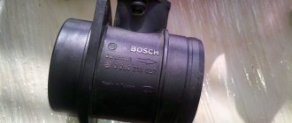
Electrical diagram 2110 injector 8 valves
The front part of the VAZ 2110 injector diagram
Rear half of the diagram
Complete diagram of VAZ-21102 injector (controller “January-4”)
| Position number on the diagram | Explanation of the position on the VAZ 2110 diagram |
| 1 | headlight |
| 2 | front brake pad wear meter |
| 3 | signal |
| 4 | cooling fan |
| 5 | rear light switch |
| 6 | electricity storage |
| 7 | generator vaz 2110 |
| 8 | oil pressure sensor |
| 9 | oil level sensor |
| 10 | spark plugs |
| 11 | sprayers |
| 12 | empty control |
| 13 | ecu terminal blocks |
| 14 | dpdz |
| 15 | dpkv 2110 |
| 16 | ignition module |
| 17 | antifreeze heat indicator sensor |
| 18 | starter |
| 19 | diagnostic block |
| 20 | dtozh |
| 21 | speed meter |
| 22 | petrol pump connection relay |
| 23, 35, 39 | circuit breakers |
| 24 | electric gasoline pump |
| 25 | micromotor reducer for heater damper |
| 26 | recirculation throttle |
| 27 | stove fan |
| 28 | windshield air pump |
| 29 | washer level meter |
| 30 | brake fluid level meter |
| 31 | antifreeze level meter |
| 32 | VAZ 2110 wiper gear motor |
| 33 | additional heater fan resistor |
| 34 | Relay for connecting the injection power system |
| 36 | canister purge throttle |
| 37 | dmrv |
| 38 | Cooling system fan connection relay |
| 40 | size switch |
| 41 | dd |
| 42 | lambda probe vaz 2110 |
| 42* | CO potentiometer (mounted on cars running on leaded gasoline. In this case, the lambda probe is not mounted) |
| 43 | fog light control |
| 44 | rear window heating control |
| 45 | fog light switch |
| 46 | rear window heating switch |
| 47 | dashboard vaz 2110 |
| 48 | relay and fuse block |
| 49 | gasoline level meter |
| 50 | ignition lock |
| 51 | instrument backlight brightness corrector |
| 52 | steering column switch |
| 53 | Illumination lamp for heater control levers |
| 54 | hazard warning light switch |
| 55 | VAZ 2110 heater ecu |
| 56 | recirculation throttle switch |
| 57 | ECU on-board control system VAZ 2110 |
| 58 | side direction indicators |
| 59 | heat meter for heating system |
| 60 | interior lamp |
| 61 | front interior light |
| 62 | carrying socket |
| 63 | VAZ 2110 watch |
| 64 | switches in the front door pillars |
| 65 | switches in rear door pillars |
| 66 | boardlight bulb |
| 67 | front light switch |
| 68 | cigarette lighter |
| 69 | ashtray light bulb |
| 70 | brake light switch |
| 71 | rear window defroster |
| 72 | exterior rear lights |
| 73 | interior rear lights |
| 74 | room light bulbs |
| 75 | trunk light bulb |
Diagram of the VAZ engine management system with BOSCH controller - ECM 21104 1.6 16V
1 – block of the ignition coil wiring harness to the ignition system harness; 2 – block of the ignition system harness to the ignition coil wiring harness; 3 – ignition coils; 4 – immobilizer warning sensor; 5 – immobilizer control unit; 6 – spark plugs; 7 – nozzles; 8 – diagnostic block; 9 – block of the ignition system harness to the ABS cabin group harness; 10 – controller; 11 – electric fuel pump; 12 – block of the ignition system harness to the fuel level sensor harness; 13 – fuel level sensor harness connector to the ignition system harness; 14 – block of the ignition system harness to the injector harness; 15 – injector harness block to the ignition system harness; 16 – block of the ignition system harness to the side door harness; 17 – speed sensor; 18 – idle speed regulator; 19 – throttle position sensor; 20 – coolant temperature sensor; 21 – mass air flow sensor; 22 – oil pressure warning lamp sensor; 23 – phase sensor; 24 – oxygen sensor; 25 – crankshaft position sensor; 26 — knock sensor; 27 – solenoid valve for purge of the adsorber; 28 – oil level sensor; 29 – coolant temperature indicator sensor; 30 – block of the ignition system harness to the instrument panel harness; 31 – instrument panel harness connector to the ignition system harness; 32 – ignition relay; 33 – ignition relay fuse; 34 – fuse for the electric fuel pump power supply circuit; 35 – electric fuel pump relay; 36 – electric fan relay; 37 – controller power supply fuse; 38 – ignition system harness block to the air conditioner connector; 39 – instrument cluster; 40 – ignition switch; 41 – electric fan of the cooling system; 42 – on-board control system unit; 43 – starter relay; 44 – contacts of the 8-terminal blocks of the instrument panel harness and the front harness; 45 – contacts of the 21-terminal blocks of the instrument panel harness and the rear harness; 46 – trip computer; 47 – diagnostic connector.
The QG16DE engine uses a phased distributed fuel injection system. This means that each cylinder uses its own fuel injector (port injection), and fuel injection is carried out by the injector only of the cylinder in which the intake valves are in the open position (phased injection). The amount of fuel injected varies depending on the duration of the electrical pulse supplied to the injector solenoid valve from the electronic engine control unit (ECU). In general, the electronic engine control system performs the following functions:
• control of the moment and duration of fuel injection; • control of energy accumulation time in ignition coils and regulation of ignition timing; • regulation and maintenance of engine idle speed; • electric fuel pump control; • control of electric radiator cooling fans; • control of the air conditioning compressor clutch; • control of the solenoid valve for purge of the adsorber of the gasoline vapor recovery system; • control of the “CHECK ENGINE” indicator lamp; • interaction with a standard car anti-theft system (ATS) or immobilizer; • generation of diagnostic trouble codes and interaction with an external diagnostic device; • generating signals for the trip computer; • integrated engine/automatic transmission control to reduce shock when changing gears by reducing engine torque; • emergency operation mode, which allows you to continue driving if individual components of the ECM fail.
The control unit performs these functions based on the results of processing the controlled parameters. These include:
• crankshaft position; • camshaft position; • throttle position; • position of the accelerator pedal • position of the parking-neutral handle of the automatic transmission; • position of the brake pedal (from the brake light switch); • air mass flow and its temperature; • coolant temperature; • on-board network voltage; • vehicle speed; • oxygen content in exhaust gases; • presence of detonation; • presence of a signal to turn on the air conditioner; • position of the key in the ignition switch; • APS (immobilizer) password for permission to start the engine; • refrigerant pressure; • pressure in the power steering.
The block diagram of the ECM (the devices included in it) is conventionally divided into 4 groups: electronic control unit (controller), sensors, actuators, auxiliary devices. Sometimes a car uses a non-contact ignition system - the block diagram is below:
- battery;
- Ignition breaker;
- Ignition breaker relay;
- Spark plugs VAZ;
- Electronic ignition module;
- Electronic controller;
- Sensor that fixes the crankshaft position;
- Setting disk.
VAZ 2110 injector diagram
Electrical circuit for controlling the injection engine VAZ-21102, 2111, 21122 according to Russian toxicity standards (controller M1.5.4)
Injector diagram VAZ-21102, -21103, -2111, -21113, -2112, -21122 for Euro-2 toxicity standards (controllers M1.5.4N, “January 5.1”)
Electrical circuit of the VAZ-21102, -2111, -21122 injector for Euro-2 toxicity standards (MP7.0 controller)
Scheme of VAZ-2110 injector for Euro-2 toxicity standards (controller M7.9.7)
Wiring diagram of the VAZ-21114 engine injector of the VAZ 2110 car under Euro-3 toxicity standards (controller M7.9.7)
Diagram of a VAZ 2110 injector with a VAZ-21124 engine meeting Euro-2 toxicity standards (controller M7.9.7)
Electrical diagram of a VAZ 2110 injector with a VAZ-21124 engine meeting Euro-3 toxicity standards (controller M7.9.7)
Injection engine control unit diagram
Electrical connection diagram for the injection engine control system:
1. — Controller connector. 2. — Mass air flow sensor. 3. — Coolant temperature sensor. 4. — Crankshaft position sensor. 5. — Throttle position sensor. 6. — Oxygen concentration sensor. 7. — Speed sensor. 8. — Ignition module. 9. — Electromagnetic valve for purge of the adsorber. 10. — Electric fan relay. 11. — Electric fuel pump relay. 12. — Main relay. 13. — Fuse protecting the power circuit of the electric fuel pump relay. 14. — Fuse protecting the power circuits of the main relay. 15. — Fuse link. 16 - Fuse protecting the constant power supply circuit of the controller. 17. — Diode. 18. — Idle speed regulator. 19. — Injectors. X1. — Diagnostic block. X2. — Connection block to the vehicle electrical system.
Connection diagram 2110
Wiring diagram for connecting the starter VAZ 2110 model 57.3708 or 2110-3708010-02
| Position number on the starter connection diagram 57.3708 or 2110-3708010-02 | Explanation of position |
| 1 | electricity storage |
| 2 | generator |
| 3 | starter VAZ 2110 model 57.3708 or 2110-3708010-02 |
| 4 | ignition switch |
Wiring diagram for windshield wiper and washer
| Position number on the diagram | Explanation of position |
| 1 | windshield cleaner |
| 2 | windshield washer |
| 3 | windshield wiper and washer switch |
| 4 | mounting block VAZ 2110 |
| 5 | egnition lock |
| K2 | glass cleaner switch |
| K6 | Additional relyushka |
| A | Conventional numbering of plugs in the wiper motor blocks |
| IN | to sources of electricity |
Wiring diagram for connecting external lighting VAZ 2110
| Position number on the diagram | Explanation of the position on the external lighting diagram of the VAZ 2110 |
| 1 | lamp dimensions in the Faroah block |
| 2 | mounting block |
| 3 | size switch |
| 4 | ignition switch |
| 5 | Dimensions control on the dashboard |
| 6 | tail light bulbs |
| 7 | brake lamps |
| 8 | room lighting lamps |
| 9 | instrument lighting switch |
| 10 | brake lamp switch |
| 11 | VAZ 2110 on-board control system unit |
| K1 | relay for monitoring the health of lamps (contact jumpers are shown inside the relay, which must be installed in the absence of a relay) |
| A | to power supplies |
| IN | to instrument lighting lamps |
Electrical circuit for connecting an audio signal
| Position number on the diagram | Explanation of position |
| 1 | signal |
| 2 | signal switch |
| 3 | fuse box VAZ 2110 |
| A | terminal block for engine cooling fan |
| IN | to energy sources |
Modifications of the VAZ-2106 car
VAZ-21060 . Modification with the symbol VAZ-21060, Izhevsk assembly of recent years of production with a VAZ-21067 injection engine with a catalyst that meets the Euro-2 environmental standard
VAZ-21061 . Modification with a VAZ-2103 engine, some cars with a similar index were equipped with a simplified engine cooling system and did not have an electric fan. Instead, an impeller was installed on the end of the coolant pump shaft. Already Russian cars were equipped with bumpers from the VAZ-2105, some examples were equipped with cleaners and headlight washers.
VAZ-21062 . Export, right-handed modification of the base six.
VAZ-21063 . A car with an improved VAZ-21011 engine, with an oil pressure sensor and an electric engine cooling fan. The release of this modification was completed in 1994.
VAZ-21064 . Export, right-handed modification, like the VAZ-21062, but the VAZ-21061 modification was taken as the basis
VAZ-21065 . A modification of the car with improved equipment, which was produced from 1990 to 2001. An engine with a volume of 1569 cm3 was installed as a power unit. Other differences from the base model include a more powerful generator, a 5-speed gearbox, a rear axle gearbox with a gear ratio of 3.9, a contactless ignition system, and a Solex carburetor. There were other changes both in the exterior and in the interior, in general it was a “luxury” version of the VAZ-2106 sedan.
VAZ-21065-01. The same VAZ-21065 but with a VAZ-2103 engine
VAZ-21066 . Export, right-hand drive modification of the VAZ-21063 car.
VAZ-21068 . A car that was produced as a carrier of units during the development period of the new VAZ-2108 and VAZ-21083 engines.
VAZ-21069 . Modification of the VAZ-2106 manufactured by order of the special services. It was equipped with a two-section rotary piston engine VAZ-411 with a power of 120 hp, VAZ-413 with a power of 140 hp.
VAZ 2110 fuse circuit
Internal electrical connection diagram of the VAZ 2110 fuse box
Here is an electrical diagram of the internal connections of the fuse box of a VAZ 2110 . Connection lines for fuses and relays are marked on it. The symbols for these electrical safety devices are indicated. To better understand which relay protects what, a symbol of the electrical device being protected is marked next to it. The diagram shows plug connectors. The inner number indicates the terminal number on the plug, and the outer letter and number indicate the connector number.
Location diagrams of fuses and relays on different VAZ 2110 mounting blocks
This page presents three mounting blocks of fuses and relays for the VAZ 2110 car and its modifications. They all have their own designation. These blocks have different layouts of relays, spare fuses and auxiliary tweezers. These three mounting blocks are installed on different modifications of the VAZKH 2110 vehicle.
When is it necessary to change the sensor?
The fuel sensor must be replaced if at least one of the following reasons occurs:
- contacts are so destroyed that there is nothing left to protect;
- resistive tracks are worn to the limit;
- there is damage to the float. This is rare, but it happens. Ruptures lead to the fact that the latter fills with gasoline and sinks, showing an empty or half-empty tank,
- even when it is full;
- The slider itself is damaged.
In case of the above-mentioned defects, the FLS must be replaced.
VAZ 2110 wiring diagram
Wiring diagram for turns and hazard warning lights for VAZ 2110
| Position number on the diagram | Explanation of position |
| 1 | turn signal lamps in headlights |
| 2 | mounting block |
| 3 | ignition switch VAZ 2110 |
| 4 | hazard warning light switch |
| 5 | side turn signals |
| 6 | turn signal lamps in rear lights |
| 7 | turn switch |
| 8 | instrument cluster |
| K3 | turn signal and emergency flasher relay |
| A | to a source of electricity |
Electrical wiring diagram for connecting the trunk lock
| Position number on the wiring diagram for connecting the trunk lock | Explanation of position |
| 1 | fuse box VAZ 2110 |
| 2 | trunk lock switch |
| 3 | trunk lock motor |
| A | to sources of electricity |
| IN | numbering scheme for plugs in the gearmotor block |
Door lock system wiring diagram
| Position number on the diagram | Explanation of position |
| 1 | mounting block VAZ-2110 |
| 2 | fuse 8 A |
| 3 | ECU |
| 4 | Right front door locking motor |
| 5 | Right rear door locking motor |
| 6 | left rear door locking motor |
| 7 | left front door locking motor |
| A | to power supplies |
| IN | terminal numbering diagram in the control unit block |
| WITH | numbering scheme for plugs in locking gearmotor blocks |
Electrical wiring diagram for the rear window heating system
| Position number on the diagram | Explanation of position |
| 1 | connection block |
| 2 | ignition switch VAZ 2110 |
| 3 | rear window defroster switch |
| 4 | heating switch control |
| 5 | rear window defroster |
| K6 | additional relay |
| K7 | rear window heating relay |
| A | to sources of electricity |
Wiring diagram for the ignition system of a VAZ 2110 carburetor engine
This diagram was installed on VAZ 2110 with a VAZ-2110 carburetor engine, with a contactless ignition system.
| Position number on the diagram | Explanation of the position on the ignition system wiring diagram | Article number according to VAZ catalog |
| 1 | Nut M6 | 00001-0058962-11 |
| 2 | Washer 6 special | 00001-0011974-73 |
| 3 | Ring sealing | 21080-3706701-00 |
| 4 | Bunch of wires | 21080-3707080-10 |
| 5 | Spark plug | 21080-3707010-00 |
| 6 | Ignition coil wire | 21080-3707150-00 |
| 7 | Lock washer 6 | 00001-0026053-70 |
| 8 | Washer 6 | 00001-0026444-01 |
| 9 | Wiring harness | 21100-3724026-10 |
| 10 | Wiring harness | 21100-3724037-00 |
| 11 | Nut M5 | 00001-0058964-11 |
| 12 | Spring washer 5 | 00001-0011954-70 |
| 13 | Washer 5 | 00001-0005193-01 |
| 14 | Ignition coil | 21080-3705010-00 |
Wiring diagram for the ignition system of an injection engine with an ignition module
| Position number on the diagram | Explanation of the position on the ignition system diagram | VAZ catalog number |
| 1 | Fuel level sensor wiring harness | 21120-3724037-20 |
| 2 | Injector wiring harness | 21110-3724036-00 |
| 3 | Spark plug | 21110-3707010-00 |
| 4 | High voltage wiring harness | 21110-3707080-00 |
| 5 | Ignition system wiring harness | 21102-3724026-02 |
Wiring diagram for the ignition system of a 2112 injection engine with an ignition module
| Position number on the diagram | Explanation of the position on the VAZ 2110 ignition system diagram | VAZ catalog number |
| 1 | High voltage wiring harness | 21120-3707080-01 |
| 2 | Spark plug | 21120-3707010-00 |
| 3 | Injector wiring harness | 21120-3724036-00 |
| 4 | Fuel level sensor wiring harness | 21120-3724037-20 |
| 5 | Ignition system wiring harness | 21103-3724026-11 |
Wiring diagram for VAZ 2110 engine ignition system with individual ignition coils
| Position number on the diagram | Explanation of the position on the ignition system diagram | VAZ catalog number |
| 1 | Ignition coil wiring harness | 21104-3724148-00 |
| 2 | Spark plug | 21120-3707010-00 |
| 3 | Injector wiring harness | 21120-3724036-00 |
| 4 | Fuel level sensor wiring harness | 21120-3724037-40 |
| 5 | Ignition system wiring harness | 21104-3724026-00 |
| 6 | Additional wiring harness | 21102-3724100-10 |
VAZ2107 fuse and relay diagram
The electrical wiring of the machine is protected by fuses, which are mainly installed in the central and additional units, located at the bottom of the instrument panel on the left side next to the steering column. The circuit from the battery to the terminals and connections is closed when the car ignition is turned on.
F1(16A) Klaxon, lamp socket, cigarette lighter, brake lamps, clock and interior lights (plafonds) F2(8A) Windshield wiper relay, heater and wiper motors, windshield washer F3(8A) Left headlight high beam and warning lamp on high beam F4(8A) High beam of the right headlight F5(8A) Low beam fuse of the left headlight F6(8A) Low beam of the right headlight and rear fog lamp F7(8A) This fuse in the VAZ 2106 block is responsible for the side light (left sidelight, right rear light), trunk light, license plate light right light bulb, instrument lighting lamps and cigarette lighter light F8(8A) Side light (right sidelight, left rear light), license plate light left light bulb, engine compartment lamp and side light warning light F9(8A) Oil pressure gauge with warning lamp, coolant temperature and fuel level indicator, battery charge warning lamp, direction indicators, carburetor choke indicator, rear window heating F10(8A) Voltage regulator and generator excitation winding F11(8A) Reserve F12(8 ) Reserve F13(8A) Reserve F14(16A) rear window heating F15(16A) Cooling system fan electric motor F16(8A) Turn indicators in hazard warning mode
Owners of 2106 should be aware that the old design of fuses has long become obsolete, since each time they operate they overheat, which affects the density of the cells. Lack of tight contact between the fuse and the connectors leads to their burning. Therefore, replacement of the fuse blocks is necessary. To avoid unnecessary problems with the electrical wiring, you should inspect the safety devices every six months. If the contact part burns, it is necessary to replace the fuses and clean the sockets. Today, many VAZ 2106 owners are modernizing classic blocks, replacing them with modern blade fuses.
Electrical cooling circuit for VAZ 2110
| Position number | Explanation of the position on the engine cooling diagram |
| 1 | fan motor |
| 2 | motor activation sensor |
| 3 | mounting block VAZ-2110 |
| A | to sources of electricity |
Malfunctions in vehicle operation with a faulty FLS
If a faulty VAZ 2110 fuel level sensor is not repaired or replaced in a timely manner, this can damage the submersible fuel pump, for which hydrocarbons serve as a cooling medium. When the level of gasoline in the tank is below a critical level, this leads to the pump running dry, overheating and may fail. At the same time, the latter is not so bad. Overheating can cause a fire, and, accordingly, even greater damage to the car.
In addition, the filter meshes become clogged with dirt from the bottom of the gas tank, which also harms the gas pump.
Wiring diagram of the VAZ 2110 generator model 94.3701
| Position number on the diagram | Explanation of the position on the connection diagram for the generator model 94.3701 |
| 1 | car battery |
| 2 | generator VAZ 2110 |
| 3 | mounting block |
| 4 | ignition switch |
| 5 | power supply charge control on the dashboard. |
How to replace a fuel level sensor with your own hands: step-by-step instructions
When the fuel sensor in a VAZ 2110 does not work, and all attempts to revive it have failed, all that remains is to replace it with a new one. You should not save on this device and delay the purchase of a new one. Moreover, its price is low, it is in the range of 350-500 rubles.
The FLS replacement is carried out from inside the car. To get to the gas tank, you have to remove the rear seat.
Important. When performing this work, you must follow safety rules. It is recommended to work with open doors.
The fact is that when replacing the sensor you will have to open the tank, and gasoline is a rather volatile and explosive chemical compound. The vapors of this hydrocarbon mixture can quickly fill the car interior. When working with a gas tank, you should never smoke or light matches to avoid a fire.
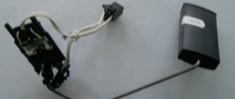
Now that you, dear reader, have been warned, you can proceed to replacing the faulty VAZ 2110 fuel level sensor with your own hands. The back seat was removed and the device was unscrewed from the gas tank. The new sensor is ready to be installed in place.
When buying a new device, you should pay attention to two points:
- When choosing a new sensor, it should be the same model as the old one. Pay attention to the numbers indicated on the body of the old device. Better yet, write them down for yourself and save them.
- Pay attention to the connector. When buying a new device, make sure that it is similar, since the number of ends on the connector for the FLS may vary: some models have three, while the FLS for injection engines has 4.
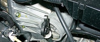
Before removing the old device, you must unclip the connectors holding the sensor.
Access to the gas cap is located under the rear passenger seat. To get to it, you will have to remove the seat from the car. Then you should disconnect the pump by removing its chip. To relieve pressure, you need to start the engine. It will stall almost immediately, because without a pump no gasoline will flow to it. If the car has not been started during the day, then there is no need to start the engine. The pressure dropped on its own a long time ago. Resetting is necessary so that when the cap with the sensor is unscrewed, fuel does not spill out of the tank.
- 17mm wrench for unscrewing the fittings;
- Phillips screwdriver for removing the cover;
- Head 7 (for unscrewing the pump);
- After turning off the pump and releasing the pressure, unscrewing and removing the cover, you need to unscrew the fittings on the tank as shown in the picture.
Now you need to carefully remove the fuel pump. Remember that it is submersible, so it is drowned in gasoline. So you should remove it carefully, allowing the fuel to drain back into the tank.
Carefully set the pump aside, and then you can remove the float.
Assembly is performed in reverse order. Only instead of the old one, a new FLS is installed.
That's all! We hope our publication was useful to you and helped you cope with a faulty fuel level sensor on a VAZ 2110.
Source
Heater diagram 2110
| Position number | Explanation of the position on the VAZ 2110 heater diagram |
| 1 | fan motor |
| 2 | additional resistor |
| 3 | VAZ 2110 controller |
| 4 | assembly block |
| 5 | ignition switch |
| 6 | cabin air temperature meter |
| 7 | recirculation switch |
| 8 | recirculation valve |
| 9 | micromotor gearbox for heater damper drive |
| A | to the instrument lighting switch |
| IN | to sources of electricity |
Video “How to repair wiring yourself”
Find out more about how electrical circuit repair is carried out in a garage from the video below (video author - Ramanych).
Wiring in a car plays one of the most significant roles, since it is actually the connecting link of many functional elements of the car. In the VAZ 2110, wiring is replaced if it malfunctions, or if the owner decides to upgrade. This, in turn, will help to significantly improve the efficiency of the vehicle's electronic systems. Often, old wiring simply cannot withstand the load of various additional high-tech devices. Replacing the wiring in a VAZ 2110 can be easily done on your own.
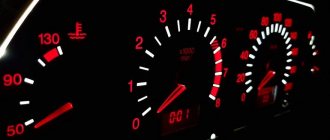
Electrical diagram of the VAZ 2110 panel
| Position number on the diagram | Explanation of position |
| 1 | fuel reserve warning light |
| 2 | right turn signal lamp |
| 3 | right turn control |
| 4 | left turn indicator |
| 5 | TOZH index |
| 6 | external lighting signal light; |
| 7 | oil pressure warning light |
| 8 | parking brake control |
| 9 | battery charge indicator light |
| 10 | tachometer VAZ 2110 |
| 11 | "Check engine" warning lamp |
| 12 | speedometer vaz 2110 |
| 13 | brake fluid level warning light |
| 14 | alarm control |
| 15 | high beam warning lamp |
| 16 | fuel level indicator |
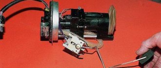
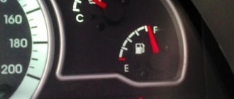
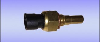
What is a fuel sensor
The fuel level sensor (FLS) is a control and measuring device that transmits information about the amount of fuel to the dashboard to the fuel level indicator (FLI), located on the dashboard next to the speedometer.
The operating principle of the FLS is simple: the fuel sensor is built into the gas tank system, consisting of a check valve, filter and fuel pump. A similar fuel supply and control system is used in injection engines. It is built into the gas tank cap and screws in with it.
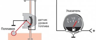
This device is typical for diesel engines and is installed on the side as a separate unit. In this case, a float with a lever for tubular devices is placed inside the tank, and the movement of the latter determines the level of fuel in the tank.
FLS device
In modern cars, LENs are installed mainly of lever and tubular types. In general, their operating principle has a lot in common, although upon closer examination some differences can be found between them. The VAZ 2110 is equipped with proven lever sensors. They are reliable, give a small error, but periodically fail. Sometimes their service life can be extended with simple manipulations, but sooner or later it becomes necessary to completely replace the VAZ 2110 fuel level sensor.
The figure shows a diagram of the VAZ 2110 fuel level sensor.
Wiring diagram for connecting door power windows 2110
| Position number on the diagram | Explanation of position |
| 1 | mounting block |
| 2 | ignition switch VAZ 2110 |
| 3 | Right front door power window switch |
| 4 | Right rear door power window switch |
| 5 | Right front door power window motor |
| 6 | Right rear door electric window motor |
| 7 | left rear door power window motor |
| 8 | Left front door electric window motor |
| 9 | left rear door power window switch |
| 10 | left front door power window switch |
| 11 | power window switch |
| A | to power supplies |
| IN | to the instrument lighting switch |
| WITH | the order of conditional numbering of terminals in power window blocks |
How to preserve a VAZ-2111 in winter
In order for the VAZ-2111 to serve for a long time, it is necessary not only to promptly eliminate faults related to the operation of the electrical circuit, but also to properly maintain the car. Experts give the following recommendations:
- Washing is good, but after cleaning the car it won’t be superfluous to treat the body parts with liquid wax. Why is this necessary? Wax fills even the smallest pores that appear in the paint, and dirt does not penetrate there, which means you can save money on another wash.
- If you are not satisfied with the roughness that a rag leaves after wiping off dirt, use polishing and rub the liquid glass. The latter will keep the VAZ-2111 in the best condition for at least 1.5 years.
- Many owners of domestic cars want to turn a boring vehicle into a real modern car. To do this, owners stick stickers on the surface, but no one takes into account that they are a real dust collector for small debris and dirt.
- Drive your car with care - service station workers assure that any scratch can be retouched by painting the part, but they do not specify that it is almost impossible to select an identical shade of paint previously used by the manufacturer. Therefore, the entire car has to be repainted.
- The headlights of the VAZ-2111 are made of plastic - this is how the designers take care of the recycling of raw materials. But plastic wears out over time and becomes cloudy. To extend the life of your headlights, initially protect the surface with armored film.
- There is an opinion that seat covers prevent abrasion of the seats themselves, but this is not the case. Moreover, it is easy to wash the seats; special products are used for this.
Replace your wipers promptly; they will protect the glass from scratches.
This free collection contains all the necessary documentation for the electrical equipment of the VAZ-2111 car - the circuit itself, the heating system, headlight cleaner, electronic engine control module and fuse box. The VAZ 2111 is the first station wagon in the line of front-wheel drive cars, which is a modernized concept of the rear-wheel drive VAZ 2104. In it, the wiring diagram for the injector and a number of other components have undergone changes as part of the concept change. Diagrams for other models can be viewed here.
Electrical diagram of VAZ 2110 headlights
Wiring diagram for headlights and fog lights
| Position number on the diagram | Explanation of position |
| 1 | block headlights |
| 2 | mounting block |
| 3 | headlight switch |
| 4 | size switch |
| 5 | fog light control |
| 6 | fog lamps in rear lights |
| 7 | fog light switch |
| 8 | Ignition switch VAZ 2110 |
| 9 | high beam headlight control on the instrument panel |
| K4 | headlight low beam switch |
| K5 | high beam connection switch |
| A | to sources of electricity |
| IN | terminal block for connecting headlights of another model |
Headlight adjustment diagram
Wiring diagram for fog lights
| Position number | Explanation of the position on the fog lamp connection diagram |
| 1 | fog lights |
| 2 | fog light connection stick |
| 3 | fuse box VAZ 2110 |
| 4 | switch size |
| 5 | fog light switch |
| A | to power supplies |
| IN | to the instrument lighting switch |
Electrical diagram for connecting headlight cleaners
| Position number | Explanation of the position on the headlight cleaner connection diagram |
| 1 | headlight cleaners |
| 2 | headlight washers |
| 3 | switch for headlight cleaners and washers |
| 4 | size switch |
| 5 | mounting block |
| 6 | ignition switch VAZ 2110 |
| 7 | connector for headlight cleaners and washers |
| A | to the instrument lighting switch |
| IN | to power supplies |
| WITH | numbering of plugs in headlight cleaner housings |
Basic principles
It doesn’t matter what kind of engine the Lada is equipped with - it could be a VAZ 2110 injector or a 2110 carburetor - the basic electrical components in this model will not be different. Below are the main features that the VAZ 2110 wiring has:
Below are the main features that the VAZ 2110 wiring has:
- Any electrical equipment, as well as devices that are powered by electricity, is based on a single-wire connection. Lada engineers equipped the electrical wiring with wires of different colors, and each of them is responsible for the operation of certain functions. Accordingly, certain devices will be connected to the circuit through a specific wiring harness. Thanks to this, the car enthusiast has the opportunity to understand the nuances of the wiring himself, especially since, if necessary, he himself will be able to repair certain elements.
- The VAZ 21102 has 8 or 16 valves, it makes no difference, the minus is the ground, that is, it is connected to the vehicle body.
- As for the positive cable, on an 8- or 16-valve engine it will always be red. So, if the VAZ 2110 wiring is being replaced or repaired, there is no need to change the color of the wires, otherwise you will confuse yourself in the future.
- Each equipment or system associated with the vehicle’s electrical circuit is equipped with a separate cable harness.
- The tenth model of the VAZ family is designed in such a way that when the battery is activated, the entire electrical circuit and equipment operate under voltage. Therefore, when performing any work related to the on-board network, you should always disconnect the battery.
- Remember that there is also a contactless system. As a rule, it is necessary in order to create a high-quality spark when starting the engine, which also contributes to better combustion of the combustible mixture. For the normal functioning of such a contactless system, it is necessary to use high-voltage cables (the author of the video is MR. BORODA).
Carburetor models
The first models of 8- and 16-valve VAZ 2110 cars were equipped only with carburetor engines. A few years later, the domestic automobile concern began to equip its vehicles with injection engines. Of course, the injection model is more advanced, but today in Russia and the CIS countries tens of thousands of carburetor cars with 8- and 16-valve internal combustion engines are used.
Most likely, dozens of owners are interested in the question: is the circuit different on carburetors and injectors 21102 or not? In principle, there are no special differences between these versions in terms of the electrical circuit. Almost all systems used on injection 8- and 16-valve engines are identical to carburetor units. Accordingly, if you need to replace a carburetor engine with an injection one or install additional devices, then there will be no problems with this. If you look into the engine compartment, you will notice that both versions of the car even have the same outputs and plugs.
One of the main points that must be taken into account when replacing a carburetor with an injector is the connection of the fuel pump. In order for the fuel pump to always work correctly, it is necessary to additionally install wiring to power it to the control unit.
Injector
In addition to the fact that the electrical wiring in the carburetor and injection versions is virtually identical, the injector has certain features. For example, it is equipped with fuses, and also in the injection versions of the car there are a larger number of sensors.
In fact, as a result of the fact that these vehicles are equipped with a large number of different sensors designed to provide ECU functionality, the system itself is more complex. It should be noted that carburetor versions do not have an electronic control unit. To repair the system if necessary, you need to clearly know about all its components and their installation locations. The electrical circuit itself in any car is divided into the engine compartment and the interior. Above you can familiarize yourself with the electrical circuit diagram, and below are its main symbols.
Tens ignition circuit
Ignition circuit for VAZ 2110 carburetor engine
| Position number on the VAZ 2110 diagram | Explanation of position |
| 1 | ignition coil |
| 2 | ignition distributor sensor |
| 3 | spark plugs |
| 4 | switch VAZ 2110 |
| 5 | ignition switch |
| A | to sources of electricity |
Wiring diagram of the ignition switch with the key inserted
| Position number on the diagram | Explanation of position |
| 15 | ignition system contact, generator excitation, headlights, turn signal, control devices, windshield and rear window wipers and washers and headlights, automatic heater control system |
| 30 | contact plus |
| 50 | starter terminal |
The KZ-881 ignition switch uses an LED instead of an incandescent lamp.
How to determine if there is a fault in the electrical network
First of all, the red light will light up, signaling a failure or serious problems in the car’s electrical systems, even if you installed a Europanel instead of the factory version. Immediately take the following steps to identify it and do not ignore the warning under any circumstances; this is why the light bulb was made threateningly red. Don't ignore the problem!
Let's start diagnostics:
- see if everything is ok with the generator. Is it put on well, is it sagging? This procedure must be done with all versions of the fuel system, both carburetor and injection. It also doesn’t matter whether you have a standard configuration or 16 valves;
- We check the fuses on the VAZ-2112 according to the electrical diagram that we discussed above. The reverse side of the safety block cover will also be of great help. There are clues there that the diagram will help you decipher. Replace the burnt out element and try to start the car again. If the light goes out, then we have solved the problem;
- If the red light on the dashboard does not decrease, you need to check whether the battery terminals are tightly connected and whether they have oxidized. Is the wire going from the battery to the generator and to the starter damaged?
The stove does not blow at the feet of a VAZ-2112
These are some recommendations for eliminating widespread difficulties associated with faulty electrical networks of a VAZ-2112 car with 8 or 16 valves. Of course, this review cannot examine all problems and provide information on how to fix them. For example, where to look for the reason for the de-energization of turn signals or pumps that ensure stable operation of the vehicle.
It’s good that the cooperation of car enthusiasts and their timely tips help save time, money and nerves when the car needs repairs.