So, in 2109, the fuel level sensor (FLS) is connected through the mounting block (BL - black box) and then into the panel. In 2114, the sensor is connected directly to the panel.
Your task: find the FLS contact in the CHYA and connect it to the panel. This contact is located in block Ш9, pin number 6, wire color is pink. Two wires come out of the FLS: pink (which we need) and blue-red (not needed in 2114). The pink wire, as I already wrote, is located in the block, which is connected to the CY. But don’t try (like I did at first) to look for this connector under the hood. It is located in the salon. The wires go under the driver's seat and are connected to the CY from the passenger compartment. To the left of the clutch pedal, under the carpet (or whatever you have) is a strip of these wires. Find the connector and remove it from the CN. Find the pink wire in it, there is one of them, remove it from the block. The block is returned to the ChYa. We extend 15-20cm of wire onto this pink wire and pull it into the panel. In the panel we disconnect the red block, find pin 10 (pink thick wire), remove the terminal, wind a new wire (that you have built up) in this pink one in any way. We put the terminal back. The ignition and fuel gauge must turn on.
The wire for the fuel reserve light is NOT REQUIRED; the panel will turn it on itself when the fuel level is low.
Now, connect the External Temperature Sensor (ETS).
Actually, we buy a sensor. Called VDO External Temperature Sensor for Double Window Panel. It also needs a connector. There are two wires at the output. The resistance on them at 10-15 degrees is approximately 4-5 kOhm. As the sensor heats up (breathe on it), the resistance should drop to 1-2 kOhm.
Connection. The sensor is connected with one (any) contact to the panel, the second to the body (ground). It is also connected to the red block of the panel in the first contact (which is located separately, on the side, located differently from everyone else). There is already a blue-red wire there. We take it out, screw the wire from the DVT onto the terminal and put it back. Depending on where you will install the sensor, extend the wires to the required length. I installed it under the panel in the interior and increased it by 10-15cm. Firmly fix the sensor, the second wire on the body or on the battery (whichever is closer). Then, ALWAYS, remove the (-) terminal from the battery for a couple of minutes. It is necessary to reset the panel to find the sensor. We put the terminal back, the sensor should work.
Many owners of domestic cars do their own repairs and tuning. If they need to repair or replace electrical equipment, they need to know where a particular wire or connector is connected. For this purpose, there is a pinout of the VAZ 2114 dashboard with a detailed description of their location.
It is worth noting that this car was equipped with VDO and Schetmash devices at different times, which have some differences. Our article presents the pinout of the VAZ 2114 instrument panel for both panel options, indicating the purpose of all blocks, wires and connectors.
The instrument cluster from VDO is more modern. It has stylish LED backlighting, as well as some differences in connecting certain connectors from the previous version. Such devices were installed both at the factory on the latest cars of this model, and are often installed independently by car owners. For example, some drivers install a panel from Lada Kalina.
The pinout of the VAZ 2114 instrument panel in this case looks like this:
Since such a tidy is also used on the Lada Kalina, equipped with more modern equipment, some inputs when installed on 2114 will remain free, since this car does not have such equipment (unless, of course, it was additionally installed by the owner himself).
Schetmash
The “Schetmash” instrument panel was set to “fourteenth” from the first days of production. Subsequently, VDO devices began to be installed on the car. But even among the cars of recent years, there are sometimes cars with this panel.
For this device, the pinout of the VAZ 2114 instrument panel is as follows:
For white block (X1):
For the red chip (X2):
- 1 purple-blue - to the outside air temperature sensor;
- 2 orange - fuse F16;
- 3 black - weight per body;
- 4 white — dashboard lighting;
- 5 blue - to the right direction indicator;
- 6 black and blue - to the left turn indicator;
- 7 pink-blue - brake fluid level sensor;
- 8 brown - leads to the on-board computer;
- 9 yellow-gray - sensor indicating speed;
- 10 pink - fuel level sensor;
- 11 black-green - fuse F14;
- 12 – to the alarm;
- 13 purple - terminal 50 on the ignition switch.
As can be seen from the description, the location of certain connectors on the instrument panels is slightly different. When replacing the device with a more modern one, or vice versa, the motorist may experience some connection difficulties. Therefore, if you have no experience in auto electrics, it is better to entrust such tuning to specialists.
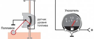
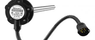
The fuel level sensor of a VAZ 2114 car measures the amount of fuel in the tank. It transmits measurement readings to the fuel volume indicator located on the instrument panel of the vehicle.
Symptom Definitions
To find the reason that led to the failure of the VAZ 2114 brake lights, you need to have an almost standard set of motorists. Using the tools listed below, you can easily determine the cause of your car's brake lights not working.
Required tool:
- Multimeter;
- Screwdriver;
- Sandpaper (sandpaper);
- A set of keys;
After preparing the necessary tool, you can begin troubleshooting.
Troubleshooting
There can be a huge number of reasons for failure, but as a rule, there are problems of the same type that occur quite often and carry standard solutions.
Main reasons:
- Blown fuse link;
- Breakdown of the brake pedal sensor (frog);
- Brake light bulb filament burnt out;
- Oxidation of the contact on the lamp socket;
- Oxidation of the connector of the entire flashlight;
- Damage to the flashlight board;
- Broken wire;
All of the above reasons are, to one degree or another, the same type and the most common.
Causes of problems
The functioning of the device is disrupted for the following reasons:
- There is no normal contact in any part of the circuit (wires have broken off, areas where connectors are connected are oxidized, solder joints are cracked).
- The indicator on the instrument panel is faulty.
- The float has become detached from the sliding contact.
- The fuse has blown.
- There is no contact between the resistive track and the sliding contact. This happens if oxides appear on the sensor, the contact pressure on the resistive layer weakens, and the tracks wear out.
Signal diagram
Before you start talking about finding and fixing this malfunction, you should first talk about the electrical circuit of the signal (after all, without knowing it, it will be difficult to carry out repair work).
It is immediately worth noting that the electrical circuit of the sound signal is quite simple and includes:
- switch mounted on the steering column;
- fuse;
- electrical relay;
- sound signal device;
- connecting wires.
You can study the circuit diagram of the device in more detail using the following drawing:
Why does the sensor give incorrect readings?
The fuel level sensor of a VAZ 2114 car may not work correctly, giving false readings, for the following reasons:
- There is additional resistance in the circuit - the connectors have oxidized, deposits have appeared on the resistive layer and the sliding contact.
- The float casting was deformed, causing the float to fill with fuel. This cause of malfunction occurs infrequently.
- A coating has formed on the guide, making it difficult to move the float.
The fuel gauge indicator always shows that the tank is completely full if the float has come off the sliding contact. In addition, such a malfunction may be due to the fact that the wire that goes to the instrument panel has a short, causing the resistance in the circuit to decrease.
Why do you need a relay?
The seller persistently sold me a relay for 40 rubles, saying that I couldn’t live without it. But in the end, it worked out without him.
What is the point of a relay?
First version (MYTH) The point is that the VAZ and Volgov circuits for connecting sound signals are not the same. Volgov's horns take ground from the body, while VAZ's horns take ground from the connected wire. According to the sellers, when we press the beep, we close the ground (-) and not (+). Therefore, if you connect without a relay, the horn will work constantly. But in reality, everything turned out quite the opposite, which made the work easier. Therefore, we proceed as follows.
Second Version (more real). Volgovsky buzzers consume a current of 14A, and a standard buzzer 5.5A. Due to excessive load, the fuse may melt, and if you set its rating higher, the tracks on the board will melt.
If you want to install a relay, install it, but I didn’t install it, because... The loads applied to the beep are not constant and short-term.
Self-replacement
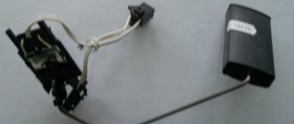
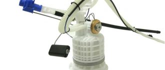
To replace the fuel level sensor you will need:
- new device;
- resistance meter;
- screwdrivers;
- open-end spanners.
Remember that the fuel level sensor on the VAZ 2114 is located near the fuel, which means you need to follow safety precautions. First turn off the battery. It is not necessary to completely dismantle it; you just need to disconnect the negative wire. Make sure the tank is no more than 45 percent full. This will greatly simplify the replacement procedure.
Procedure
The broken device is located directly in the fuel tank. Follow this algorithm:
- The device is located in the module together with the fuel pump. Therefore, it is impossible to pull out the sensor alone without hitting the module.
- To access the module, remove the lower cushion on the rear seats and move the trunk lining.
- Using a seven key, unscrew the fasteners that hold the fuel tank cap.
- You will see 8 screws pressing the edges of the cork. Unscrew them.
- Slightly move the tank cap to the front.
- Disconnect the electrical connectors from the pump using a size 17 wrench. Unscrew the nut of the fuel supply hose from the fitting.
- Take your time, be careful. Make 1 preliminary revolution. This will make it possible to reduce the pressure accumulated under the lid.
- According to the diameter of the plug you will find 8 nuts. Unscrew them.
- When dismantling the pump, lift it, turn it clockwise and tilt it. This minimizes the chance of damage to the measuring float.
- Using a flathead screwdriver, move the ring stopper on the module.
- Remove the module cover.
- Remove the end of the connected wire from the terminal of the device responsible for regulating the pressure.
- Release the clamps of the meter and slide it along the holes in the housing.
- Remove the sensor.
Now you only need to replace the removed meter with a new one and repeat all the above procedures in reverse order.
Examination
It is a mistake to assume that damage to high-voltage wires does not in any way affect the condition of the module itself.
Many people think of simply replacing high-voltage elements, but in reality they will still have to change the module. This is explained by the fact that damaged or defective wires direct the wrong current, the configuration of which does not correspond to the necessary parameters. As a result, the spark hits inaccurately or ineffectively, causing the module to burn out and become unusable.
In general, the best option for checking the ignition module on a VAZ 2114 is to use an oscilloscope. But, firstly, not every driver has it, and secondly, few people can use them. Therefore, we will carry out the check using improvised means:
- 12-volt light bulb;
- Tester (available for little money at any auto parts store).
Let's start with preliminary manipulations with the accompanying elements of the ignition module.
- Check the wiring harness. It is disconnected and the voltage indicator is checked.
- To do this, fix the tester on contact A, and connect the other terminal to engine ground.
- In normal condition, the voltage reading will be 12V.
- If there is no voltage, most likely the fuse has blown.
- If everything is fine, transfer the terminals of your tester to contacts A and B, start the car. In this case, the starter should turn and the 12-volt light should blink.
- In the absence of these phenomena, we can talk about the presence of a break in circuit A of the contacts.
Next we go to the ignition module itself.
There are several ways to check the condition of your unit. Therefore, let's look at each of them.
- Set the tester to ohmmeter mode. Use it to measure the resistance on the high-voltage lines going to cylinders 1 and 4, and then, by analogy, to the wiring of cylinders 2 and 3. In normal condition, the device will give you readings from 5.2 to 5.5 ohms.
- Give the device a gentle tug. Thus, you will shake the wiring block and the module. Moreover, this must be done in the operating mode of the power unit. If the device works without obstruction when loosened, everything is fine, you are lucky. If not, you will again have to study the condition of the wiring.
Third way
The third method is considered the simplest, since it involves replacing your device with a similar one that works exactly. But to do this, you have to find a full-fledged twin. We are talking about an ignition module from a car similar to yours in terms of year of manufacture and power unit used. It’s just that 1.5-liter engines have modules, and 1.6-liter engines have coils.
But to replace a module with a module, you will have to first dismantle yours. This is done as follows:
- Remove the negative terminal from the battery, which will allow you to turn off the power to the car;
- Disconnect four high voltages from the ignition module;
- Disconnect the wire block. To do this, you need to release the special clamp that holds the block on the module;
- Next, unscrew the three nuts. With their help, the module is held on the bracket;
- There are three long pins on the bracket, from which the module can simply be pulled off.
Having dismantled your module, you can put another unit in its place, thereby verifying the functionality of that one and the malfunction of yours.
Checking the device with an ohmmeter
It is not always necessary to immediately replace the sensor with a new one. It happens that the problem lies in a completely different component of the car, for example, an injector. Also, if the meter is faulty, it may be possible to repair it. Before replacing, check the sensor:
- To test the device, connect a resistance meter to its terminals. This indicator must be measured when the lever and float are in extreme positions or in the middle.
- In the lower position, meaning zero fuel level, the resistance should be 285–385 Ohms.
- In the central position, which means the tank is half full, the ohmmeter should show 100-135 ohms.
- The highest position is a 100 percent filled tank. The ohmmeter should read 7–25 ohms.
If in at least one position the readings obtained diverge from normal, repair or replace the sensor. After installing the new meter, make sure that the installation arrow on the module cover is directed towards the trunk. Otherwise, you will need to dismantle the system again and repeat the replacement.
Fuse blown
The easiest and first-priority check that should be carried out when the horn fails is the integrity of the fuse. So, if the latter actually burned out, therefore, in the 2114th VAZ model there is a short circuit. You need to try to install a complete fuse according to the rating. If it burns out again, it is possible that a short circuit has occurred. In the opposite situation, most likely, the fuse has simply exhausted its resource.
Self-repair of the fuel level sensor
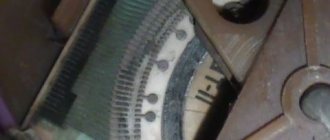
Even an ordinary motorist can repair the FLS in a VAZ 2114. Spare parts for the sensor are sold at an auto supply store. You need to remove the device from the tank and familiarize yourself with its parameters. The marking is located on the front of the plate, directly above the rheostat scale.
If there is a hole in the float, then it will be easy to fix the problem. Pull the float out of the retainer socket and install a new one. If the rheostat scale strips are dirty, they need to be cleaned. The plate must be cleaned with a soft cloth or cotton wool soaked in alcohol. If the wires come off, they can be carefully put back in place by soldering. A cracked plate needs to be replaced with another one.
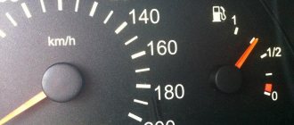
The indicator needle does not deviate from the beginning of the scale, regardless of the amount of gasoline in the fuel tank.
Fold down the rear seat and remove the indicator sensor hatch cover. Disconnect the pink wire from the pointer sensor and connect it to ground. Turn on the ignition:
– the pointer arrow has deviated – the sensor is faulty (replace);
– the pointer arrow does not deviate – continue troubleshooting.
Remove the instrument cluster from the panel without disconnecting the pads from it. Turn on the ignition. Connect the wire to the right contact 4
fuel level indicator (which connects to pin
10
of the red block):
– the pointer arrow has deviated – there is a break in the wire connecting the pointer and the sensor;
– the pointer arrow does not deviate – replace the pointer.
The indicator needle is on the scale regardless of the amount of gasoline in the fuel tank.
Disconnect the red block with wires from the block 3
instrument clusters. Turn on the ignition:
– the pointer arrow has deviated to the beginning of the scale – the pointer is working;
– the pointer arrow does not deviate – the pointer is faulty (replace).
The tachometer and speedometer can only be checked on stands in specialized workshops.
We present two diagrams for connecting the fuel level sensor of VAZ 2108, 2109, 21099 cars and their modifications with a carburetor engine.
Electrical diagram for connecting the fuel level sensor for VAZ 2108, 2109, 21099 cars with mounting block 17.3722 and a “low” instrument panel (before 1998 onwards)
Electrical diagram for connecting the fuel level sensor for VAZ 2108, 2109, 21099 cars with mounting block 2114 and a “high” instrument panel (after 1998 onwards)
Features of the fuel level sensor connection diagram
Notes and additions
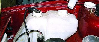
— The fuel level sensor (FLS) of VAZ 2108, 2109, 21099 cars is installed in the gas tank on the fuel intake. It is a float rheostat that changes its resistance depending on the position of the float. Read more: “Fuel level sensor for VAZ 2108, 2109, 21099 cars.”
More articles on the fuel system of VAZ 2108, 2109, 21099 cars
Click to enlarge (600 KB)
Description:
In the instrument panel wiring harness, the second ends of the white wires are brought together into one point, which is connected to the instrument lighting switch (except for the white wire, from plug “4” of block “X2” of mounting block 28 to display block 83 of the on-board control system). The second ends of the black wires are also brought together to points connected to ground. The second ends of the yellow wires with a blue stripe are brought together to a point connected to plug “4” of the block “X1” of the VAZ-2114 mounting block. The second ends of the white wires with a red stripe are brought together to a point connected to plug “10” of the “X4” block of the VAZ-2114 mounting block. And the second ends of the orange wires are also brought together to a point connected to plug “3” of the “X4” block of the VAZ-2114 mounting block.
* Installed on parts of manufactured Lada VAZ-2115 cars; ** On VAZ-2115 vehicles of various configurations, one common washer pump and solenoid valves for headlights and windshield washers can be installed (as on VAZ-2108 and VAZ-2109 vehicles). In this case, the pads 12 are connected to the washer pump, and the wires connected to pumps 13 and 14 are connected to the corresponding solenoid valves.
The modern VAZ 2114 model is in demand among domestic drivers due to its sufficient reliability, optimal cost and high maintainability. The only drawback of the model is the poor build quality. Some cars suffer from frequent electrical failures. Consequently, users often try to deal with breakdowns on their own, which without the necessary knowledge can aggravate the situation.
Do it yourself: Replacing the sound signal.
Good day everyone!
I’ll repeat myself in part for those who are “off topic”)
Unexpectedly, I discovered that the sound signal stopped making any sounds ((
I use it extremely rarely - in emergencies, and I remember for sure that during the technical inspection it was checked - it worked.
I like “diagnostics at the AM level”)
Responsive and caring users will always give advice and this time they really helped (on the forum about breakdowns https://avtomarket.ru/remont/VAZ/2114/r5493/)
As it turned out, without approaching the car, the fuse is intact (after all, the fan is working!