Sensor Features
The VAZ fuel level sensor in most models has virtually no different design features.
The FLS is a device with a float mounted in the gas tank of a car. Thanks to the position of the float, we get an idea of the amount of gasoline in stock - the lower it goes, the less the amount of fuel will be. The operating features of this device have minor differences depending on the type of engine. It doesn’t matter the carburetor or injector in your system - the principle of operation and location of the sensor remain the same. The measuring device, as mentioned earlier, is located in the tank, and can be accessed by tilting the rear passenger seat. This will come in handy if you need to check the sensor for functionality or replace it.
When it becomes necessary to check it:
- The sensor does not show the gasoline level or is lying by several points. Sometimes the deviation from the truth is so great that it confuses the driver.
- The device arrow is frozen in one position or does not move from the Zero mark.
- Sometimes the opposite happens, when the arrow moves chaotically across the entire field.
Reasons for replacement
You will definitely have to replace the sensor if the car starts to produce the following:
- The fuel level indicator needle “dances” or has fallen dead to the zero position;
- The indicator is constantly on, indicating a critical fuel level, although you have just filled the tank full.
FLS diagram
FLS on high and low panels
The differences in the sensors on the injectors and carburetors are minimal. Also, the fuel level sensors on VAZ 2109 cars equipped with a low and high panel are slightly different.
The difference lies in the resistance indicators. These parameters must be known when checking the condition of the sensor resistor.
| Panel type | Resistance readings |
| High panel |
|
| Low panel |
|
In this regard, when buying a new fuel level sensor, be sure to ask for a controller for a high or low panel, depending on what kind of car you have. It is also important to note that in the case of injection engines, the sensor is located inside the fuel pump, but it is based on the same operating principle as a carburetor one.
DIY repair
If the sensor is equipped with a porous component, there are several options for changing it:
- You can remove it from the retainer socket and install a new one, securing it.
- Or replace the float itself along with the rod.
The second option is more preferable because it is easy to implement. If the surface of the strip on the rheostat scale is dirty, the element is cleaned.
The cleaning procedure is performed exclusively with cotton wool or a soft cloth pre-treated with alcohol. The use of harsh materials or other products is not permitted. This will damage the working layer of the scale; it is quite thin, so it can cause the rheostat to break. The element cannot be repaired; it will have to be replaced.
If the contacts of the electrical circuit come off the controller, they must be carefully soldered back or connected at the point of damage. Plates with mechanical damage (cracks, fractures) cannot be repaired, only replaced. If the sensor gives incorrect readings, the problem can be corrected by adjusting the angle on the so-called rod. This element is designed to fix the float. To get accurate readings, the angle is bent in different directions.
Gasoline sensor for VAZ 2109 (carburetor, injector)
If suddenly the fuel gauge needle drops down or behaves somewhat inappropriately, there is no need to worry too much. You can easily fix the problem yourself if it is a faulty sensor.
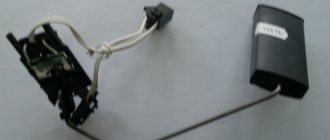
Appearance of the device
You should not ignore a breakdown of the fuel level sensor (FLS), because in the absence of information about the remaining amount of fuel, you run a high risk of not getting to the gas station, but stopping somewhere in the middle of nowhere.
Location
If usually most repair work related to the engine and its system is carried out through the engine compartment, then in the case of the fuel level sensor everything is somewhat different.
FLS location
Reasons for replacement
You will definitely have to replace the sensor if the car starts to produce the following:
- The fuel level indicator needle “dances” or has fallen dead to the zero position;
- The indicator is constantly on, indicating a critical fuel level, although you have just filled the tank full.
FLS diagram
FLS on high and low panels
The differences in the sensors on the injectors and carburetors are minimal. Also, the fuel level sensors on VAZ 2109 cars equipped with a low and high panel are slightly different.
The difference lies in the resistance indicators. These parameters must be known when checking the condition of the sensor resistor.
Panel type
Resistance readings
In this regard, when buying a new fuel level sensor, be sure to ask for a controller for a high or low panel, depending on what kind of car you have. It is also important to note that in the case of injection engines, the sensor is located inside the fuel pump, but it is based on the same operating principle as a carburetor one.
Functionality check
Do not rush to throw out the old sensor and replace it with a new regulator. First you can try to check if it really doesn't work.
To check, you will have to extract the “suspect” in any case.
- Inside the car, remove the lower part of the rear seat, remove the soundproofing material, if any. This will give you access to the inspection hatch in the floor of the car.
- Using a Phillips screwdriver, unscrew the four mounting screws that hold the hatch in place. Take it off. Under the hatch you will find a sealing gasket made of rubber. In any case, even if the old sensor works again for the benefit of your car, this gasket should be replaced.
- Disconnect the power supply block with wires from the sensor, and then unscrew the fastening nuts around the perimeter that hold the desired fuel level sensor on the tank body. Usually there are 6 of these nuts, and to dismantle them you will need an 8 socket socket or a regular wrench.
- Under one of the nuts there is a ground wire attached to a stud. Remove the wiring and put it aside for now. He shouldn't interfere.
- Carefully remove the sensor and do not forget to remove the rubber sealing gasket, which is located directly under the regulator. If there are signs of damage or defects on it, be sure to replace this component.
- When the sensor is removed, visually check its current condition. If there are mechanical damages, there is no point in further trying to repair it or restore its functionality. Change it right away.
- If there is no visual damage, check the condition of the float. It can be depressurized, that is, there is fuel inside it, cracks and various defects through which fuel has leaked are visible on the surface of the element. If all of this is present at the float, replace the entire sensor.
- Be sure to blow out the fuel filter with compressed air. A useful event that definitely will not harm your fuel system. Especially if the quality of gasoline with which you fill your VAZ 2109 leaves much to be desired.
- Check the condition of the resistor. To do this, you will need a multimeter in ohmmeter mode. Connect a measuring device to the sensor terminals and take readings. In the lowest position (empty tank), the resistance should be about 315-345 Ohms. If the tank is half full, the resistance will be 108-128 ohms. And when the tank is empty, the ohmmeter should show no more than 7 ohms. If the parameters differ from those specified, or there is no resistance at all, this indicates a malfunction of the controller. It must be replaced.
Reasons for replacement
You will definitely have to replace the sensor if the car starts to produce the following:
- The fuel level indicator needle “dances” or has fallen dead to the zero position;
- The indicator is constantly on, indicating a critical fuel level, although you have just filled the tank full.
FLS on high and low panels
The differences in the sensors on the injectors and carburetors are minimal. Also, the fuel level sensors on VAZ 2109 cars equipped with a low and high panel are slightly different.
The difference lies in the resistance indicators. These parameters must be known when checking the condition of the sensor resistor.
Resistance readings
In this regard, when buying a new fuel level sensor, be sure to ask for a controller for a high or low panel, depending on what kind of car you have. It is also important to note that in the case of injection engines, the sensor is located inside the fuel pump, but it is based on the same operating principle as a carburetor one.
Disassembly of the unit, its reassembly
To check the functionality of the VAZ 2108, VAZ 2109 sensor, it is necessary to disassemble the unit. You will need the following set of tools:
- screwdriver;
- key to 7;
- replaceable head for 10.
The following actions are performed sequentially:
- We recline the back seat and see the lid. Use a Phillips screwdriver to unscrew the fasteners and remove the compartment cover.
- There are a bunch of wires in the compartment, all of them must be carefully disconnected one by one so as not to damage them. This is where the 7 head comes in handy.
- Next, use a 10mm head to unscrew the fuel sensor itself, and then remove it from the gas tank. This should be done carefully, without jerking.
This completes all manipulations to disassemble the sensor assembly. Now the device can be cleaned, resistance checked or replaced. If there is external mechanical damage on the device body, you don’t even have to check it, but it is better to immediately replace it with a new one. The sensor cannot be repaired, just like its spare parts. Assembly is carried out in the reverse order, without any changes. Before connecting the wires, it is advisable to check their integrity. This is all that may be needed when dismantling the unit.
Which crankshaft oil seal to install on a VAZ 2109, when to change it?
Original number 2108-1005034, average price 62 rubles.
- Elring 546.968 — 57 rub.
- Reinz 80-33653-10 — 49 rub.
- Corteco 12016518B — 83 rub.
Replacement frequency: every three years or every time the timing belt is replaced.
Using a 17 key, unscrew the oil pan plug and drain the oil into a container with a volume of at least 4 liters. The duration of draining the oil is at least 10 minutes. We wrap the drain plug.
Using a 10mm wrench, unscrew the two side bolts of the front timing cover.
And another one in the center. Remove the timing cover. Remove the generator drive belt.
Remove the right wheel and the plastic shield of the engine compartment. Using the “19” head, turn the crankshaft clockwise by the pulley mounting bolt.
Rotate the lower pulley until the mark on the camshaft toothed pulley aligns with the installation tab on the rear timing cover.
By removing the rubber plug in the upper part of the clutch housing, we make sure that the mark on the flywheel is located opposite the slot in the clutch housing cover.
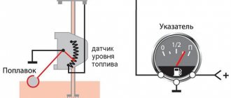
Operating principle of the fuel level sensor
Depending on the principle of operation of the sensors, the malfunctions that may occur with them will differ slightly. Let's look at the operating diagram of each type of fuel level sensor.
Float lever FLS
The operating principle of a float-type level sensor is based on the use of a rheostat. A lever is attached to its central part, at the end of which there is a float. Depending on the fuel level in the tank, the float will move, moving the rheostat lever accordingly along the contact path. During such movement, the resistance will change, which is recorded by the vehicle's electrical system. Accordingly, the arrow on the instrument panel will move in accordance with the indicated resistance on the rheostat. By the way, at a certain position of the float, and therefore the resistance value on the rheostat, a warning lamp on the dashboard will light up, indicating that there is little fuel left in the tank and refueling is necessary.
For clarity, let’s look at the operation of the fuel level sensor using the example of VAZ-2108/VAZ-2109, VAZ-21099 cars. Their design can use two sensors - for a high and low dashboard. They are structurally similar, but have different operating resistance. Specifically, for a high panel sensor, a resistance value between 238 and 262 ohms means the fuel tank is empty. With a resistance of 59...71 Ohms, the fuel gauge needle is approximately in the middle (accordingly, the tank is half full). If the resistance is within 17...23 Ohms, then this means that the car’s tank is completely filled.
As for the sensor for the low panel, the situation is similar. So, with a resistance of 285...335 Ohms, the arrow points to an empty tank. At 100...135 Ohms, the arrow will correspond to half, and at a value of 7...25 Ohms - at the end of the scale, pointing to a fully filled tank.
The specified resistances are important in the context of testing the sensor, since if it fails, the first thing to do is to check the internal resistance of the sensor using an electronic multimeter.
Please note that the indicated resistance values are relevant only for the listed VAZ models. For other machines, the corresponding values must be looked for additionally in the technical documentation (manual) attached to them. However, even these indicators can be used as a guide!
Tubular FLS
The design of the sensor is based on a housing with a guide post (actually a tube), at the other end of which there is a wire with a contact group (chip). The design also includes a float with slip rings located inside a hollow tube. The housing flange is secured using mounting bolts on the top wall of the fuel tank. By the way, this is a disadvantage of this type of sensor and imposes a limitation on its use. In particular, tubular type sensors can only be installed on tanks whose height is sufficiently large.
The operating algorithm of the tubular fuel level sensor is as follows:
- On the tube that touches the bottom, in its lower part, there is a hole (or two) through which fuel enters inside.
- The float located inside the tube has contact rings and when moving through the tube, as the fuel level in the tank changes, the resistance also changes. Resistance is measured using one or two contact wires located along the guide tube.
- The movement of the float on the surface of the fuel naturally changes the value of electrical resistance on the contact wire when power is applied to it.
- At the moment when the float is in the upper position (the tank is completely full), a small section of the contact wire is activated, and accordingly, the resistance value is minimal. At the moment when the tank is empty, the float is at the lower extreme point, respectively, the length of the signal wire is maximum, which also corresponds to the maximum electrical resistance.
The resistance of the fuel level sensor will differ for different cars, so when measuring you need to use technical documentation.
Electronic FLS
Electronic fuel level sensors are installed on cars that use high-quality gasoline and diesel fuel produced on a biological basis. This not only provides very accurate sensor readings, but also allows the actuator to “avoid touching” the fuel directly. However, the peculiarity of using such sensors is that it does not provide smooth monitoring of the fuel level (in small steps). The design of contactless FLS is based on an inactive magnetic sensor. The diagram of the fuel level sensor according to which it works is as follows:
- The main part of the sensor is located in a sealed housing. Only the magnetic sensor (MAPPS) and its lever are in contact with the fuel.
- The movement of the float with a magnet occurs along a sector defined by metal plates of different lengths. A signal corresponding to a certain fuel level in the tank is generated depending on the position of the magnet on a separate plate.
The fuel level indicator in this case is formed using a discrete method since the amplitude of the feedback signal will change from segment to segment that the magnet passes through. Depending on the model of a particular sensor, the signal amplitude and other technical information differ. The operating error of such a system does not exceed 0.5%...1%, but the cost is also significantly higher than a conventional contact system, so these FLS data are installed only on business and premium class cars.
Causes of malfunction
The reasons why the fuel level sensor does not work or it shows incorrectly are the following faults:
- The float has lost its seal. This situation is relevant when a ball made of fragile plastic is used as a float, which can crack as a result of mechanical stress or as a result of operating the car in severe frosts. In this case, the float will be inside the liquid or, more often, it will simply sink and fall to the bottom. The result will be a constant reading from the device that there is no fuel in the tank. Repair measures include replacing the float or the entire assembly. Another rare option is that the float can simply detach from the lever on which it is attached and “go off on its own.”
- Deformation of the lever that holds the float. As a result, the float may lose mobility or reflect incorrect information. Often this situation occurs when the fuel module is inaccurately removed from the tank, but sometimes even as a result of long-term operation of the car on roads with uneven surfaces, that is, with constant vibrations while driving. You can try to return the lever to its original shape, but most often the corresponding lever is simply replaced with a new one.
- Damage to the sensor housing. As a result, the readings of the resistive elements may change or the lever that takes the corresponding readings may be damaged. In this case, the reason why the sensor does not show the fuel level correctly is the use of low-quality gasoline or mechanical shock loads on the part.
- Failure of resistive elements. This is a fairly common reason why the fuel level sensor does not work. Elements on the rheostat fail for natural reasons, that is, as a result of abrasion during long-term use. It is possible that the wear is partial, for example, in the middle. In this case, the instrument needle will twitch. It is also possible that there is no contact between the sliding element and the resistive track due to damage or wear of the resistive coating or loosening of the slider foot pressure. With such a malfunction, the arrow will lie at zero.
- Lack of electrical contact in a certain section of the circuit. As a rule, on contacts that are oxidized either by moisture or fuel. The wires, their insulation, or breakage may be damaged. There are also sometimes problems with electrical connectors.
- The signal wire has a short to ground. In this case, the value of its resistance will be distorted and tend to zero. With such a malfunction, the level sensor incorrectly displays the level, transmitting information that the tank is completely filled.
- The fuse responsible for the operation of the fuel level sensor has blown. The fuse number must be found in the electrical diagram of the specific vehicle.
- Failure to secure the sensor on the fuel tank body. For example, with a skew. As a rule, in such a situation, the smell of fuel spreads outwards, in particular, the smell of gasoline will be heard in the cabin.
- There are cases when the resistive board on which the slider moves simply falls off the fastening solder.
- Tubular fuel level sensors may have a broken signal wire. In this case, the arrow will constantly show an empty tank.
- Also, tubular sensors are characterized by a coating that can form on the guide post. This will naturally make it difficult (and even impossible) for the float to move. Plaque is usually formed as a result of using low-quality fuel (with a large amount of paraffin, gasoline instead of gasoline). In this case, the instrument needle will freeze in one position, and not necessarily in one of the extreme ones.
- For non-contact sensors, the magnetic sensor and/or its wiring may be damaged. Some of them have a special control and control board installed. The problem may be with her too. In this case, the sensor usually fails completely, that is, it does not indicate the fuel level at all.
Most often, problems arise with floats or resistive elements, which wear out over time and stop transmitting correct data. But note that when the fuel level is not displayed, it is not always the sensor that is to blame. Often the arrow does not work, and here the device on the panel, which, in fact, is a potentiometer, is to blame. Therefore, if the fuel sensor does not indicate the fuel correctly, then you need to remove it and check it with a multimeter and make a visual inspection.
FLS installation process
FLS installation is carried out by partners in 100% of cases. Clients, as a rule, do not have the qualifications, experience and desire to install FLS on their own. The reasons for reluctance are not only technical, but also organizational and social (obstruction of innovations in control, sabotage and vandalism of drivers, etc.).
To install the FLS you must have:
- A team of 2 people (it is difficult for one person, for example, to dismantle the tank)
- Tools Bimetallic crown for metal (often with a diameter of 35mm)
- Angle drill
- Metal drills (often titanium nitride, yellow)
- Phillips and slotted screwdrivers
- Pliers (nippers, pliers, etc.)
- Hacksaw or pipe cutter
- Riveter (for securing the FLS to thick-walled tanks)
- Calibration equipment Calibration tube
As a rule, professional installers have a special technical vehicle. It contains tanks for draining fuel and a station for pumping fuel.
In addition to equipment, you need to have theoretical training and experience in solving non-standard situations.
Now let’s take a closer look at the installation process of each type of FLS.
Ultrasonic FLS
To install, you need to clean the area outside the bottom of the tank, glue the FLS there and secure it with a clamp placed around the tank. After this, the power supply is connected to the FLS and calibration is performed.
- The ultrasonic FLS is installed externally at the bottom of the fuel tank. For installation, the geometric center of the tank bottom is selected.
Operating time is approximately 4 hours.
Capacitive FLS
To install a capacitive FLS, you need to remove and evaporate the fuel tank, make a hole at the top of the tank, insert the measuring part of the FLS into it and secure the FLS with self-tapping screws to the surface of the tank. After this, the power supply is connected to the FLS, calibration and calibration are performed.
- Before installation, all fuel must be drained from the tank. Then you need to get rid of the fuel vapors remaining in the tank after draining the fuel. If this is not done, then when drilling a hole, an explosion will occur due to a spark (especially after using gasoline). To do this, the tank is dismantled, water is poured into it, drained (repeat), and then evaporated (the process is called “tank evaporation”).
- For installation, the geometric center of the tank is selected.
- A hole is made in the geometric center of the tank; metal shavings should not fall into the tank.
- The measuring part of the FLS is cut slightly shorter than the height of the tank - this way fuel can freely flow between the tank tubes. For trimming, use a pipe cutter or a hacksaw.
- Calibration in progress. This will allow the FLS to know its new length after trimming. To do this, the FLS is turned over with the measuring part up and completely filled with fuel. After 1-2 minutes, the fuel is drained.
- The capacitive FLS is installed in the hole made so that the measuring part is inside the tank, and the board with the interface cable is outside.
- The sensor is fixed to the surface of the tank with self-tapping screws. There are holes in the metal base of the top of the sensor on which the board is attached for self-tapping screws.
- The FLS is connected to the vehicle's on-board electrical network and to the computer. A special adapter is used for this. Software for setting up the FLS is installed on the computer.
- Calibration is in progress.
- The FLS is disconnected from the computer and connected to the tracker. Tracker installation is complete.
Operating time is approximately 4 hours. Training video from Omnicomm (10 minutes)
Connection to CAN bus
To connect to the CAN bus, you must first find it in the car. The CAN bus is two wires twisted into a twisted pair. There are many wires in a car, and there may be more than one CAN bus. Therefore, it is very difficult to find the right CAN bus without documentation about where it goes.
When it is found, a “CAN crocodile” is used to read the data (recommended) or connected directly to copper wires (less preferable).
Dut vaz 2109 injector high panel
We present two diagrams for connecting the fuel level sensor of VAZ 2108, 2109, 21099 cars and their modifications with a carburetor engine.
Electrical diagram for connecting the fuel level sensor for VAZ 2108, 2109, 21099 cars with mounting block 17.3722 and a “low” instrument panel (before 1998 onwards)
Electrical diagram for connecting the fuel level sensor for VAZ 2108, 2109, 21099 cars with mounting block 2114 and a “high” instrument panel (after 1998 onwards)
Features of the fuel level sensor connection diagram
Notes and additions
— The fuel level sensor (FLS) of VAZ 2108, 2109, 21099 cars is installed in the gas tank on the fuel intake. It is a float rheostat that changes its resistance depending on the position of the float. Read more: “Fuel level sensor for VAZ 2108, 2109, 21099 cars.”
Appearance of the device
You should not ignore a breakdown of the fuel level sensor (FLS), because in the absence of information about the remaining amount of fuel, you run a high risk of not getting to the gas station, but stopping somewhere in the middle of nowhere.
Fuel level sensors VAZ 2101-2107
The period of development of high technologies affected almost all areas of human activity, including the automotive industry. Carburetor engines are being replaced by so-called injection engines, the operation of which is controlled by various types of sensors. Modern cars with injection control systems contain a large number of them.
This article will focus on one of these sensors, namely the fuel level sensor (FLS). For car enthusiasts interested in this device, I will try to briefly outline the answers to questions such as:
- Features of the FLS device.
- Principle of operation.
- Main signs of a malfunction.
- Is it possible to repair the FLS?
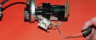
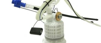
The sensor is located directly in the car's gas tank. Let's look at what elements the FLS consists of on most Lada cars. The sensor is attached to the base of the fuel pump and consists of the following elements:
- a reading device with a float connected to it;
- connectors for power supply and connection to the fuel pump.
The idea of work is to correspond the level of gasoline in the tank to a certain sensor signal. By measuring the fuel level, the sensor transmits data to the car's dashboard. There are several options for such sensors, but their purpose is the same. The main signs of failure of the FLS are: the arrow on the instrument panel constantly moves; when the tank is fully filled, the arrow is in the zero position; Regardless of the fuel level, it does not move at all. Before replacing the sensor, you should check the fuse responsible for its operation and the wires for breaks.
The FLS is a fairly reliable device and lasts a long time. Of course, repairing this sensor is possible, but it is not a fact that after repair it will serve you for a long time. Given its difficult-to-reach location, I consider it advisable to replace the sensor with a new one so that it does not take up your time and effort in the future. The cost of a sensor for domestic cars currently fluctuates around 400-450 rubles.
In conclusion, I would like to warn car owners against the occurrence of unforeseen situations associated with the failure of any elements of the vehicle’s electrical equipment. When replacing various electrical devices, be it sensors or lighting bulbs, for complete safety, I advise you to disconnect the terminals from the car battery.
I hope after reading this article you have received a sufficient amount of information about how the fuel level sensor works and the principles of its operation.
Why the sensor may not show
Cases when the fuel level sensor does not work on a VAZ 2107 are not at all uncommon. Experienced owners of 7s know what can cause a device to break down. Moreover, sensor breakdowns occur equally often on both carburetor and injection VAZ 2107 models.
The fuel level sensor or FLS is a rheostat made of nichrome wire. The position of the moving contact is changed using a float. The device is located on both injection and carburetor models inside the tank. The only difference is that the injection sevens additionally have a fuel pump, which is located next to the sensor. If the fuel gauge does not work, then there is a high probability that there is a malfunction of the sensor in the tank.
Failures of this device manifest themselves in different ways:
- The pointer indicator is constantly in the “0” position.
- When the car moves, the needle tends to “jump,” which also indicates a malfunction in the fuel level control system.
- When the ignition is turned on, the needle on the fuel level indicator is at zero, but when driving, after a while it begins to function.
- The indicator (light) does not light up, indicating that the amount of fuel in the tank is reduced.
What causes the fuel quantity indicator in the tank on the seven to not work needs to be disassembled in detail, this will help you find out where to start repair work. The causes of breakdowns are:
- The sensor fuse has blown - this element must be checked first so that you do not have to do unnecessary work. If the fuse is blown, the dial indicator will always show “0”.
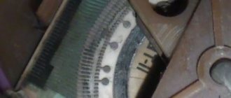
- The board tracks are worn out - this type of malfunction is directly related to the sensor on which the tracks are erased due to their wear-out. This type of breakdown is not considered serious, as it can be easily fixed. To do this, you need to bend the slider so that it moves along the section of the track that has not yet been erased.
- If the true fuel level in the tank is distorted, it is necessary to adjust the sensor regulator. To solve the problem, you will need to change the position of the FLS pins. Changing the position of the pin is done by moving it to the side until the pointer arrow moves to “1”. The arrow in positions “0” and “1” must be stationary, and if it moves when installed in these positions, then it is necessary to bend the pin accordingly.
- Oxidation of the FLS contacts, which also causes the indicator to become inoperable. To eliminate the breakdown, you will need to clean the contacts.
- The sensor float is damaged - depending on the fullness of the tank, the float moves the moving contact of the rheostat to the appropriate position. The float is a sealed volume of air. If the integrity of the float is compromised, fuel gets inside, which results in the display of incorrect data.
Only after it has been determined why the fuel indicator is not working can the appropriate repair actions begin. However, to identify a breakdown, you will need diagnostics, which every owner of a domestic car can carry out.
Checking the fuel level sensor
Before replacing the fuel level sensor on a VAZ 2107, it is recommended to first verify the causes of the breakdown. Further manipulations should be carried out according to the instructions:
- You need to disconnect the pink wire from the sensor located inside the gas tank. In this case, the ignition must be turned on.
- If the arrow previously displayed a full tank, and after disconnecting the wire, the arrow on the fuel level indicator dropped to “0,” then the sensor itself is faulty.
- If the arrow displays a full tank when the wires are disconnected, this means that the indicator itself in the instrument panel is faulty.
- To check the pointer, you will need to remove the instrument panel, find the wires that are connected to the device and disconnect the gray wire with a red stripe.
- After disconnecting the wire, you need to turn on the ignition and observe the location of the indicator arrow. If the arrow deviates to zero, this means that the pointer is working properly, and the cause of the breakdown is a violation of the integrity of the wire.
REPAIR OF VAZ-2107 GAS TANK, FUEL SYSTEM, FILTER
The VAZ 2107 (classic) gas tank is protected from gasoline drainage!!!! Why is the fuel level sensor not working? Repair, disassembly, Toyota Haice 3L
Signs of trouble
FLS failure does not happen often, but at some point it can take the driver by surprise. Incorrect gasoline readings can result in the car owner overfilling the car tank at a gas station or running dry on the road.
Although a breakdown is a rare occurrence for this device, it becomes immediately noticeable to the car owner. The appearance of problems with FLS manifests itself in a car as follows:
- The arrow, which shows the amount of gasoline in the gas tank, constantly remains at zero, even when refueling the car;
- The arrow indicates overestimated indicators. For example, a full tank is shown when it is only half full;
- The arrow indicates underestimated indicators. For example, when filling a full tank, the dashboard displays much less.
It is not necessary to get a new device if these problems arise. In some cases, it is possible to adjust it and resolve inaccuracies.
No signal when antifreeze overheats
On the dashboard at the bottom left there is a field where the temperature of the cooling fluid is indicated. When heated to 95 °C, it is concluded that the cooling system has failed and the engine may overheat.
There are cases when the signal is not transmitted:
- Burnt out cooling sensor. This usually occurs when there is a sudden voltage drop in the on-board network. The cause may be a short circuit in the electrical wiring.
- Blown fuse. It is detected visually, it will be blackened and slightly melted, which requires replacement.
- Broken wiring. To check, you can ring it or check with a multimeter for the presence of resistance.
The incorrect functioning of the DTOZH does not have the desired effect on the increasingly displaced carburetor.
Functionality check
The VAZ 2109 fuel sensor can be checked for functionality using an ohmmeter or multimeter. After the device is removed from the gas tank, its contacts should be connected to the tester. We fix the float in one position and look at the indicators. The result should be 275-320 Ohms in the upper position of the float or 5-20 Ohms in the lower position. In the middle the resistance indicator is 100-130 Ohms. These figures are for a low instrument panel.
For a high panel these values are different:
- 260-280 Ohms in the lower position;
- 60-70 Ohm - average value;
- 15-20 Ohm is the upper limit position of the float.
If the device’s performance corresponds to the examples given, the device is working, everything is in order with the sensor, and it does not need repair or replacement. When significant deviations are present, it is worth checking the integrity of the wires. If they are ok, the sensor itself is faulty and needs to be replaced.
The FLS is working properly. What to do?
Try the following activities.
- The sensor connector has a pair of wires - pink and blue;
- The pink one controls the arrow of the fuel level indicator in the tank, and the blue one is responsible for the critically low fuel level indicator;
- Take any jumper at hand, that is, a piece of any wire, and then use the jumper to short the pink wire to ground, while turning on the ignition. At this moment the arrow should be in the full tank position;
- Now, similarly, using a jumper, we connect the blue wire to ground. This should turn on a light that indicates on the dashboard that the fuel level inside the gas tank is low;
- If, when the jumper is shorted to ground, the indicator or lamp does not work, this indicates that the indicator itself is “covered”, or there is a problem with the condition of the wiring.
There is absolutely nothing complicated about replacing the sensor. Dismantling work can be completed in 30-60 minutes with even a little experience. As for the FLS itself, it does not fail very often, but every owner of a VAZ 2109 and more should know about the features of its replacement.
TEMPERATURE SENSOR FAULTS
There are two reasons why the sensor may not transmit a signal to the dashboard. Here they are:
- The fuse responsible for the temperature sensor has blown (the sensor itself may be working properly). To understand that the problem is in the fuse, the driver will have to look under the steering column, into the fuse block of the car. A burnt fuse will be immediately visible: it usually melts slightly and turns black;
- The temperature sensor itself has burned out. As a rule, this occurs due to a sharp voltage drop in the vehicle's on-board electrical network. The cause of such a jump may be a short circuit in the electrical wiring. The fact is that the insulation of wires on the VAZ 2107 has never been of high quality. Over time, it becomes unusable and begins to crack, which ultimately leads to a short circuit.
Replacing the fuel level sensor on a VAZ 2108, VAZ 2109, VAZ 21099
Welcome! Today we will discuss in detail the replacement of the fuel level sensor in the tank. The entire replacement process will be supported by pictures for your convenience, and at the very end of the article you can see a video that will describe in detail the replacement of the sensor and its configuration.
Note! The replacement process, as you have already seen from the title of this entry, will take place on cars of the “Samara” family!
Where is the fuel level sensor located? Its location is very simple, and all because it is located in the floor of the car body under the rear seat. But in order to get to it, you will first need to lift the rear seat cushion and after that, lifting up the noise-insulating material, you will be able to see the fuel level sensor installed in the floor of the car.
Note! In the photo above, the arrow indicates where this sensor is located, but as you can see in the photo, it is invisible, and all because the noise-insulating material is not bent back!
When do you need to change the fuel level sensor? It must be replaced with a new one if:
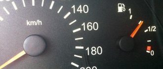
• Incorrect operation of the fuel level arrow, which is shown in the bottom photo. For example, if the sensor fails, the fuel level needle may begin to work incorrectly or may even stop showing the state of gasoline in the tank.
Fuel level sensor (FLS) for VAZ 2108, 2109, 21099 cars
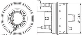
In the power supply system of the carburetor engine of VAZ 2108, 2109, 21099 cars, a fuel level sensor (FLS) is installed, designed to monitor the amount of gasoline in the fuel tank. It is located on the fuel intake in the vehicle's fuel tank. On the instrument panel there is a fuel level indicator and a fuel reserve lamp (indicator), connected by an electrical circuit to the fuel level sensor and transmitting information from it directly to the driver. The fuel level sensor (FLS) has a round flange that is attached directly to the fuel tank. On the flange there is a sensor connection block with two terminals. A fuel intake pipe and a return pipe are welded to it. The sensor itself has a plastic housing mounted on a support plate. Inside the housing there is a rheostat with a winding of nichrome wire and a fixed contact for turning on the fuel reserve lamp. The contact is connected to the sensor block (terminal “W”). The rheostat has a slider mounted on a rotating axis and connected to a movable lever, at the end of which a sealed plastic float is installed. The lower end of the rheostat is connected to the sensor block.
The principle of operation of the fuel level sensor for VAZ 2108, 2109, 21099 cars
The float moves down or up when the fuel level in the gas tank drops or increases. At the same time, the slider connected to it moves along the rheostat winding, changing the resistance at the output of the rheostat from low to high and back. A drop and increase in resistance is reflected in the movement of the needle on the fuel level indicator in the instrument panel. The level in the tank is low, the float is lowered - resistance is 285-335 Ohms (the fuel level indicator arrow is at zero), the indicator arrow shows the tank half - resistance is 100-135 Ohms, the tank is full (the arrow is all the way to the right, the float is raised) - 7-25 Ohms .
In the lower position of the float, when the fuel level is at its lowest (4-7 l), the contacts on the slider and the contact of the fuel reserve lamp close. The lamp on the instrument panel lights up.
operation of the fuel level sensor (FLS) with a full tank: the float has floated up, the slider contact at the bottom of the rheostat (minimum resistance), the moving and fixed contacts of the fuel reserve indicator lamp are open (the lamp does not light up)
operation of the fuel level sensor when the fuel level in the fuel tank of a car drops: the float fell, the slider contact moved up the rheostat winding (maximum resistance), the moving and fixed contacts of the fuel reserve lamp closed (the lamp lit up)
Electrical diagram of connections of the fuel level sensor for VAZ 2108, 2109, 21099 cars
Electrical diagrams for connecting the fuel level sensor on VAZ 2108, 2109, 21099 cars with a “low” and “high” instrument panel are presented on the page “Connection diagram for the fuel level sensor on VAZ 2108, 2109, 21099 cars.” Applicability of the fuel level sensor on VAZ 2108, 2109, 21099 cars
On VAZ 2108, 2109, 21099 cars and their modifications, fuel level sensor 24.3827 and its variants are used. Its characteristics are as follows: voltage -12 V, rheostat impedance - 350 Ohm, float lever length - 115 mm, lever angle when the tank is empty - 27.5 degrees.
Operating principle of FLS
The principle of operation of fuel level sensors is classic and simple - changes in the position of the float are “read” by the control device and transmits the information via a digital or analog signal to visual control devices. The accuracy of the data determines the type and design features of the control equipment.
Lever type
The interaction of sensor elements of this type is presented as follows:
- the float constantly occupies the upper fuel level;
- a potentiometer connected to the car’s electrical network through an indicator on the dashboard, when the gas tank is completely filled, creates a resistance of about 7 Ohms, which corresponds to the “P” mark on the control device;
- when the engine is running, gasoline is consumed, reducing the amount of fuel in the tank - the float drops along with the drop in level, moving the potentiometer slider;
- the movement of the latter along the resistive plates smoothly increases the resistance to 230 - 340 Ohms (depending on the characteristics of the car), where the maximum value informs about a completely empty tank.
The reliability of this design has been proven over years of use. At the same time, the accuracy of the readings deteriorates over time due to wear of the resistive plates and the slider.
Tubular type
The operation of a tubular type sensor uses a control principle similar to the acquisition of information by lever systems, but there are fundamental design differences. Its main elements are presented:
- Housing with guide post and resistive wire.
- Float equipped with slip rings.
- Device mounting flange with a contact group for connecting control wires.
Fuel level control is carried out in the following order:
- fuel enters through a hole in the lower part of the body;
- as the tank fills, the float mechanism moves and will remain at the top point;
- its movement changes the resistance and, therefore, the tank fullness indicator on the indicator;
- at the top point, a small section of the contact wire is involved, and the resistance has a minimum value, at the bottom - the length increases, with a corresponding increase in the final indicators.
Placing the float in a limited space that smoothes out vehicle vibrations provides information about the fuel level more accurately than lever-type units. But the possibility of installation on cars is limited by the design features of fuel tanks.
Electronic (contactless)
Electronic fuel level sensors are installed in the tank when using modern types of ethanol-based, methanol-based gasoline or biodiesel, since the installation of contact units for level determination is not effective - the readings are inaccurate, and the wear of parts is high. In turn, the inactive magnetic fluid position sensor copes with the task successfully and has the following features:
- The executive part is located in a sealed housing; only the magnetic float and lever come into contact with the fuel.
- Fuel height measurements are carried out by a signal generated by a magnetic field.
- Changes are recorded by predetermined segments, the passage of which changes the amplitude of the feedback signal. So, when filling the tank “to full”, the sensor will change readings only after passing the next mark, and the driver will not be able to observe the smooth drop in level.
In order not to be left without fuel in the middle of the journey, you need to know the amount of fuel in the tank. Thanks to the device, you can understand whether or not you need to visit a gas station, how much gasoline is in the tank, and whether you can continue driving. This is not just a useful device, but a device responsible for the level of safety on the road. Modern legislation requires the presence of such a sensor and its good condition.
Causes of errors
The main reason why the fuel level may be displayed incorrectly on the instrument panel is long-term operation of the sensor.
Most often, the device is replaced with a similar one from another car model, for example, VAZ 21099, 2110. After the replacement, some drivers notice that the data is displayed incorrectly. Most often this happens if the sensor was removed from an earlier version of the car and installed on a later one, for example, from 2109 to 2110 model. In addition, incorrect data may also appear after installing the Europanel.
The reason may be in the contacts, but there is no exact solution, so if you want to change the sensor, then look for a similar model.
Another reason is a littered float. When this part of the device is left in gasoline for a long time without cleaning, it can become covered with a rather unpleasant coating. As a result, the structure becomes heavier, which leads to constantly overestimated performance, as well as to rapid breakdown of the lever and float. The float can be replaced, but only with exactly the same one, not a similar one.
Location
If usually most repair work related to the engine and its system is carried out through the engine compartment, then in the case of the fuel level sensor everything is somewhat different.
The FLS is located under the rear seat. To access it, you need to remove the seat, bend back the soundproofing material, if any, and find the controller we need in the area above the fuel tank.
FLS location
Purchasing new equipment
Repairing old equipment is not difficult if it has become unusable due to oxidation or rust formation. Wiping the device can help restore contacts, but if the device is broken, even after restoration it may display incorrect data. If the error is more than 10%, then this can significantly affect the driver’s comfort behind the wheel, as well as the risk of being left with an empty tank on the road.
Therefore, if there is an error, it is recommended to replace it with a new device. Thus, the car owner can be confident in the accuracy of the data displayed on the dashboard. The cost of spare parts is relatively inexpensive; an injector can be found within 300 rubles. The part is easy to maintain and does not require replacement often, so it is recommended that if the data is inaccurate, replace it immediately.
Purchasing new equipment ensures that correct readings are displayed. By purchasing original spare parts, the car owner can forget about replacing them within 2-3 years.
Sources
- https://artel55.ru/diagnostika-i-remont/zamena-datchika-urovnya-topliva-vaz-2109.html
- https://k-SportRacing.ru/neispravnosti-i-remont/ne-pokazyvaet-uroven-topliva-vaz-2109-inzhektor.html
- https://adm-maisk.ru/shumoizolyaciya/dut-vaz-2109-inzhektor.html
- https://moto163.ru/tyuning-i-servis/datchik-topliva-vaz-2109-inzhektor.html
- https://lemzspb.ru/provod-dut-vaz-2109/
- https://RetroTruck.ru/obsledovanie-i-remont/nepravilno-pokazyvaet-uroven-topliva-vaz-2109.html
- https://luxvaz.ru/vaz-2109/356-datchik-benzina-karbyurator-i-inzhektor.html
- https://7road.ru/drugoe/datchik-urovnya-topliva-vaz-21099.html
- https://ladafakt.ru/datchik-urovnya-topliva-vaz-2109-inzhektor.html
- https://linhai-russia.ru/remont/datchik-topliva-vaz-2109-inzhektor-2.html
- https://toyota-chr2.ru/polomki-i-remont/zamena-datchika-urovnya-topliva-vaz-2109-karbyurator.html
[collapse]