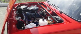
The reason that prompted me to prepare this material was the constantly and with enviable regularity that pops up the question of whether it is possible to install a contactless (electronic) ignition system on the VAZ-2121, similar to the one with which the VAZ-21213 is equipped. Since at one time I myself was concerned about this problem and successfully implemented it on my car, after which I drove with contactless ignition for more than two years before replacing the engine, I believe that my experience will be useful to those who also want to carry out a similar modernization of their car.
I won’t go into too much detail about the advantages of a contactless ignition system over a conventional contact one. This has already been done well before me. Therefore, in order to avoid repetition of already known truths, I first suggest that you take a walk through the links below and read them carefully. Everything is quite complete and well presented there:
Have you read it? Well, that's great. Now I will continue.
So, let's go to the store to buy components. At the same time, let’s carefully remember the number of the contactless ignition distributor for the “classic” indicated in the above links, or even better, write it down on a piece of paper so as not to forget. This number is indicated on the distributor body. Let’s not rely on the “competence” of sellers who can easily sell you a Niva distributor, assuring you that it must be installed on a six-wheel engine.
Also, when purchasing components, it is advisable to immediately take a spare switch and Hall sensor, since these devices have the unpleasant property of suddenly and for no apparent reason malfunctioning or breaking down, after which your car can only go further in tow. Remember that the commutator and Hall sensor are VITAL SPARE PARTS THAT MUST ALWAYS BE IN YOUR CAR! If you are a master yourself, then without much difficulty you can, if necessary, replace them, and if not, then someone who knows how to do this will replace them for you, for example the same “Angels”. But for this, the switch and sensor MUST BE AT YOUR HANDS, otherwise you will have to frantically rush around either looking for them or looking for the tractor.
When purchasing a Hall sensor, make sure that it matches the distributor you are purchasing. To do this, remove the distributor cover and compare the sensors. They must be absolutely identical. In addition, the “correct” sensor should have two ears on the sides for mounting screws, and not one in front - this is a sensor, in my opinion (I don’t know for sure), for 2108. It can also be adapted to the distributor, but the description of this work is beyond the framework of the present story.
The ignition coil must be taken for the VAZ-2108. Better than the regular type, oil-filled. I don’t presume to say for sure, but there seems to be an opinion that a “dry” type coil has a number of disadvantages, due to which the use of a conventional coil seems to be preferable.
It is also worth paying attention to the wiring harness. You need to get an ignition harness for the Niva - there are some on sale. The colors of the wires in it correspond to the colors of the wires indicated in the electrical diagram 21213, so in order to know what to connect and where, you need to have this diagram with you. When buying a harness, pay attention to how well the terminals hold in the sockets of the blocks, because when putting the blocks on the connectors of the switch and Hall sensor, the terminals, under the influence of the applied force, can jump out of the sockets and the car simply will not start. It is quite advisable to somehow better fix these terminals yourself before installing the harness.
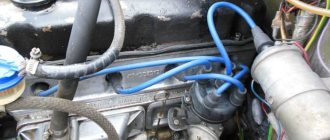
Regarding high-voltage wires, we can say that their choice is quite large. More details about this can be found in this FAQ section. I used blue Tesla silicone wires and after replacing the engine I switched them over to it. I've been traveling with them for almost three years now.
There is no need to buy an electronic control unit for the forced idle economizer (EPHH), since the carburetor 2107-1107020 “Ozone”, which is equipped with the 2106 engine, does not have an electronic control system for the idle speed solenoid valve. This block may be required only if the carburetor 2107-1107020 “Ozone” is replaced on the engine of your car with the carburetor 21073-1107010 “Solex”, which is standardly equipped with the engine 21213, and you want to equip your car with this block, so to speak, for complete set. In my opinion, this need not be done, since this unit is mainly designed to meet the environmental safety requirements of the machine, and the fuel economy obtained thanks to it can rather be considered symbolic - about 0.5 l/100 km.
But the components have been purchased and now you can start installing them. Anyone who will not do this themselves and contact a car service center may not read further, since this article is intended mainly for those who will do all the work with their own hands.
What should you pay attention to when performing work? What's important here?
1. The negative terminal from the battery must be removed.
2. When working, as already mentioned, check the electrical diagram of the VAZ-21213.
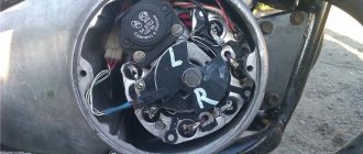
3. The best place to install the switch is the inclined part of the wall of the engine compartment, behind the battery, next to the body number (the switch should not cover the number!). Holes are drilled in this wall for self-tapping screws that will mount the switch.
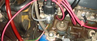
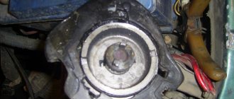
4. Before removing the old distributor, remove the cover from it and look at which cylinder the contact of the slider is directed towards. We install the new distributor with the cover removed and in the same position of this contact. If this is not done, then there may be problems with starting the engine, even to the point that the engine will not start at all.
5. The wiring harness (installed last), although it is believed to be for the Niva, the part that goes to the distributor is such a length that it would probably be enough for the engine compartment of a bus. Therefore, when laying the harness, we drag it behind the air supply box, and fold the excess part 2-3 times so that the harness can freely reach the distributor, fix this fold in several places with electrical tape and screw the entire harness in 3-4 places, again with electrical tape , to the spare tire support, from its lower side. When connecting the harness, you must try to connect the terminals so that the terminals fit tightly onto the connectors, otherwise there may be problems.
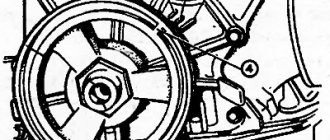
But everything is mounted and connected. We start the engine and set the OZ as is done for the 2106 engine - by placing a mark on the crankshaft pulley opposite the middle mark on the front engine cover. The installation primary SOP of the 2106 engine should be 3-5 degrees.
Installing contactless ignition on a VAZ 2107
If you are not satisfied with the operation of the standard contact ignition system of the carburetor VAZ-2107, then you can improve its operation in various ways. This article will help you choose one of them and implement it on your own.
Pros and cons of a contact ignition system.
Most carburetor “Sevens” have a contact ignition system. It is simple in design, easy to maintain and operates reliably. The contact system has been known for a long time and, in case of failure, any craftsman can fix it.
Unfortunately, this simple and ingenious design also has a lot of shortcomings. The main problem is the contacts themselves. By closing and opening the electrical circuit, they gradually burn out and change their size. This leads to a change in the ignition timing, and as a result, to a loss of power and efficiency of the engine. The slightest contamination on the surface of the contacts leads to a decrease in spark energy, and this causes difficulties when starting. And yet, the contacts are sensitive to the amount of wear on the distributor shaft bushings. Shaft play leads to uneven engine operation, especially noticeable at idle. Because of all these “charms”, the contacts need to be constantly looked after: kept clean and the gap monitored. On a car with a significant mileage, these shortcomings are especially pronounced.
Sonar IR - budget option
It is for such machines that a good solution is to replace the contact group with a contactless device, well known as Sonar IR. It works by interrupting the infrared beam with the cams of the breaker. Installing Sonar IR is quite simple. Anyone who is used to repairing their car themselves can do this. In order not to repeat the same thing ten times, I’m putting a link to a video where everything is shown in detail.
This device is installed instead of contacts
After about 50,000 km and two years, the car began to jerk when accelerating. The search for the cause led to Sonar IR. I had to put the contacts back on the road. I did not buy a new device to replace the burnt one, since I decided to replace the entire ignition system with a contactless one. From reviews on the Internet I learned that there were cases of Sonar IR overheating in a traffic jam in the summer, but this did not happen to me. If it weren’t for the brand new Nivovsky distributor I got for cheap, I would have installed Sonar IR again. The cost of the device is now about 850 rubles. He earns his money honestly.
Contactless ignition system - expensive, but annoying
This option already gives a very tangible result. A set of an ignition coil, distributor, switch and wiring harness with blocks costs approximately 2,500 rubles. Plus, it is also advisable to replace the spark plugs and high-voltage wires.
This is what the BSZ kit looks like for a VAZ classic
But for this money you get easy starting in cold weather, smooth and stable engine operation in all modes and forget about problems with the distributor. After installing the BSZ, remember firmly - you cannot remove the wires from the spark plugs while the engine is running! The sensor located in the distributor will immediately fail. But don’t be alarmed by the presence of electronic components that can “burn out” on the road - they are quite reliable. You can, just in case, buy and carry with you a spare switch and an emergency vibrator. The latter is connected instead of the burned-out Hall sensor in order to get to the repair site. If you decide to buy a kit, or assemble everything separately, keep in mind that the “3810.3706” brand distributor is designed for the Niva. It may have a shortened shaft and completely different settings. With it, the car pulls “like a tractor” at low speeds, but “sours” during acceleration. The distributor “38.3706” is designed specifically for the “Seven”; it will fit without any problems. It is better to entrust the installation of the kit to specialists.
Making a choice
For those who are not ready to spend 3,000 - 4,000 rubles for stable engine operation, Sonar IR is suitable. It will save you from the need to constantly care for the distributor and provide stable and smooth engine operation without large investments of money and time. Moreover, this is not advertising, but a purely personal opinion. If there is an alternative to the device, we will definitely test it and give a full report. If you have the financial means, no doubt install the BSZ kit, it's worth it. There is a third option - leave everything as it is. The contact system will continue to work if it is maintained in a timely manner.
High voltage wires
The contactless ignition system uses high-voltage wires of type PVVP-8 (red) with distributed resistance (2000±200) Ohm/m or PVPPV-40 (blue) with distributed resistance (2550±270) Ohm/m.
At one time, immediately after purchasing the Niva, I switched from contact ignition to contactless - BSZ. The car started up faster, kept the speed more stable, but... But this seemed not enough to me, I wanted something more. And I started studying Tyrnet. As a result, I selected three options for myself: 1 – conversion of the BSZ to “idle spark” type coils 2 – microprocessor ignition system (MPSZ) MAYA 3 – MPSZ SECU-3 On reflection, I refused to convert the BSZ - at the output we get the same BSZ, the only one with two coils instead of one (but with a more powerful spark, though). But at the same time, the possibility of changing the ignition angle remains the same - by turning the distributor body + bending the spring weights. Of the remaining two options, I chose SECU-3. Why ? Well, I liked this system))) So what we have: 1 - the possibility of several installation options: One coil - with spark distribution by a distributor. Two coils - “idle spark” type. Four coils - individually for each cylinder. Another option is the ignition module. Commutators - from one to four 2 - wide possibilities of system operation - the ignition angle can vary (depending on the installation configuration) taking into account engine speed, coolant temperature, engine load and engine detonation 3 - the ability to use ready-made “maps” - tables changes in the ignition angle, as well as adjustments to these tables. To make it more clear, after installing the MPSZ, I drove with standard tables on 27” tires. Confident acceleration throughout the entire range, smooth and stable acceleration without dips. But then I set the BF to 29” - the car began to “stupid” when I sharply pressed the gas. And now I need to experiment - in the speed range from 800 to 1500 I need to change the ignition timing. I can either raise it, relative to the preset one, or lower it. Make the change in angle both smooth and sharp. And all this is precisely and specifically only in the speed range that I currently need to adjust. 4 - the ability to write your own map But there is also a serious drawback - financial investments. I had to buy: MPSZ Absolute pressure sensor - DBP Coolant temperature sensor - DTOZh Crankshaft position sensor - DPKV Knock sensor - DD Coils Commutators Shielded wire Engine front cover Toothed engine pulley Well, and all sorts of little things))) In general, everything cost a pretty penny ( ((And considering that there is nothing in our stores, we had to order almost everything on the mainland. That is, pay for the delivery of all components by mail. Well, waste time on this very delivery ((( In addition, you need to program the unit from a laptop - this is also finance . You can, of course, program at home from a computer - but from a laptop it’s better. On a machine you can immediately monitor all the parameters. But now I’ve finally started installation! (I will describe it in exactly the order in which I installed it)
Ignition switch and features of its replacement
Ignition system module for Niva Before removing the ignition module on the carburetor or injector of the VAZ 21213, it is necessary to diagnose the ignition coil, distributor and spark plugs.
As practice shows, spark plugs are often the cause of incorrect operation of the internal combustion engine. If you are sure that the problem lies in the fault, then the installed device will need to be changed. How to replace the Niva ignition switch:
- First, the battery is disconnected and the steering column is removed.
- You need to mark the wires that are connected to the contact part of the VAZ ignition switch and disconnect them. Using a flat-head screwdriver, remove the bolt securing the system switch to the steering column bracket. You will also need to unscrew the screw that is located below, on the right side of the first one.
- Next, on Niva 21213 you need to turn the key to position 0, after which you need to use a screwdriver to slightly recess the device lock through the hole. The hole itself is located on the side of the steering column. Do not touch the exposed key.
- Before removing the ignition switch on the Niva, you need to pull it slightly towards you, after which the device is dismantled. In accordance with the connection diagram, the contact part of the device is replaced; to do this, you need to pry it off with a screwdriver and remove the retaining ring.
- Next, the contact part of the assembly is removed and changed if necessary. During installation, the rotating part must be turned counterclockwise using a screwdriver. Remove the key from the structure and install the contact part so that its wide protrusion can coincide with the wide cavity of the housing. Further assembly of the unit is carried out in reverse order.
1. Unscrew the 3Z mounting bolts.
2. Remove the assembly from its installation location.
3. Remove the contact part and replace it.
We carry out the adjustment ourselves
- The first step is to install the cylinder in the correct position. Installation is carried out so that the mark on the pulley is exactly at 0 degrees.
- Set how the slider is positioned. It should be aimed at the first pin in the cylinder.
- Use a strobe light and make sure the ignition is working properly.
- Make the electrical connections in the battery: minus to ground, plus to plus.
- The sensor must be connected to the high-voltage wire on the cylinder. The mark should connect to the crankshaft pulley.
- Start the engine at low speed (up to 800 rpm). Use a stroboscope to illuminate the pulley, and if the mark coincides with the middle mark, then the ignition is set correctly.
- Otherwise, the engine should be turned off and the meter should be loosened. In order to decrease the angle, turn the sensor clockwise; to increase it, turn it counterclockwise. Record and test the calibration again with the ignition on.
- Next, you should perform manipulations with the distribution sensor. Open the lid. Match the stator and rotor mark.
- Start the engine, bring the temperature to 75-80 degrees. When the speed is 50 km/h, sharply press the gas pedal.
- If the ignition was installed correctly, a short-term detonation will occur when you press the gas.
Also interesting: Chevrolet Niva camshaft sensor
Then there are two possible developments: early and late ignition. Let's consider solutions for both cases:
- In the case of late ignition, when there is no detonation, you should change the position of the sensor clockwise.
- In the case of early ignition, when detonation lasts longer than necessary, the sensor is rotated counterclockwise.
Niva 21213 can be subject to adjustment of the starting system by the gap at the edges of the valves, if the carburetor is removed, or by the crankshaft speed directly on the car. In the first case, the gap at the location of the lower edge (in the direction of air movement) from the throttle valve is set to a width of 1.1 mm.
It is adjusted with a screw that has a 0.7 cm hexagon on the head and a slot from the shank. This operation is carried out with the cam lever turned counterclockwise from the starting system control (all the way). In the same position, the gap at the lower edge of the air damper is set to 3 mm using a screw in the cover from the diaphragm mechanism in the starting system (you need to loosen the lock nut).
The principle of powering a carburetor engine Adjusting the Niva starting system directly in the car saves time: You need to remove the air filter from the engine, pull the control lever towards you from the air damper, and start the engine. When the air damper is forced to open (by touching a flat screwdriver to a third of its full angle of rotation) using a screw (next to the lever on the axis from the throttle valve from the first chamber), the initial rotation speed is set to 2.08.mar.0 thousand.
revolutions per minute (on a warm engine). Remove the screwdriver, lower the air damper and, using the screw stop (next to the diaphragm), set the frequency to be 100 rpm lower than the original one (you need to select the appropriate position of the air damper). The screw can then be secured using a locknut.
If you have a gas analyzer, then the carburetor adjustment in the starting system part can be done based on the amount of CO (carbon monoxide) in the exhaust gases. If, with the choke control lever fully extended, the gas rate is 8%, then everything is in order. If there is less gas than this value, then the screw on the cover of the diaphragm mechanism is tightened; if there is more, it is unscrewed and repeated measurements are taken.
It is necessary to adjust the idle speed of the Niva 2121 so that there is less carbon monoxide in the exhaust gases and so that the engine runs stably. At service stations, such work is carried out with gas analyzers on the MV. In the garage, adjustments can be made using the tachometer.
Adjusting the device For these purposes, on a warm engine, pierce the plastic plug with a screwdriver, then the quality screw is rotated in different directions until the maximum idle speed is reached. Then, using the quantity screw (has a ribbed plastic handle), you need to set an increased speed (50-70 rpm.
Design features of the Chevrolet Niva ignition switch
On VAZ-2123 cars, an ignition switch of type 2123-3704005 is used with an anti-theft locking device, a lock against re-starting the starter without first turning off the ignition, and a communication coil for the ignition key transponder with the car's anti-theft system.
Ignition switch 2123-3704005
At the ignition switch, they check the correct closure of the contacts at different key positions (see photo below), the operation of the anti-theft device and the presence of communication with the car anti-theft system.
Closing contacts at different positions of the ignition key
The voltage from the battery and generator is supplied to terminal “30”.
Connection diagram of the ignition switch with the key inserted
The locking device against reactivation of the starter must not allow the key to be turned again from position I (ignition) to position II (starter). Such a rotation should only be possible after first returning the key to position 0 (off). To unload the contacts of the ignition switch, a K6 relay is installed in the mounting block. The anti-theft locking rod should extend when the key is turned to position 0 (off) and removed from the lock. The locking rod must be recessed after turning the key from position 0 (off) to position I (ignition). The key should only be removed from the lock in position 0.
Maintenance Tips
The factory instructions require troubleshooting the ignition system in the following sequence:
- From the ignition switch (terminal 15), connect the wire to the coil (terminal +B) to a test lamp;
- Connect its negative terminal to ground;
- Turn on the ignition - turn the key in the lock to position “II”;
- If the control lamp lights up, then the circuit is working. If not, look for damage to the wire;
- With the ignition on, pull out the central wire from the coil from the distributor;
- Bring its metal tip to the cylinder block so that a gap of 3-4 mm forms between them;
- Turn on the starter for a few seconds;
- If the spark jumps, the coil is working.
Tip: you can quickly check the switch in one way - take it from a working car. If the car starts with the new switch, then you need to buy a new one.
Replacing the ignition switch on a VAZ car
To carry out repair work to replace the ignition switch of a vase, we will need: a screwdriver, a tester and a thin awl. Once you have everything you need, you can begin the repair. On all classic VAZ cars, the ignition switch is located at the bottom, on the left of the steering column. To replace you need:
- Disconnect battery
- Remove the plastic casing by first unscrewing the screws that secure it.
- Then unscrew the two screws securing the ignition switch to the bracket.
- We insert the key and set it to position 0 to disable the anti-theft device.
- Insert the awl into the hole in the bracket and press the latch. Then we take out the lock itself.
- After removal, it is recommended to mark the contact wires so that nothing is mixed up the next time you connect.
Removing the ignition switch on a VAZ-2106 begins with disassembling the steering column casing. We unscrew the five bolts and remove its halves. Before you begin disassembling the electrical part of the lock, it is very useful to disconnect the battery by removing the negative terminal or unscrewing the switch bolt. After this, remove the spring retaining ring from the back of the lock body and remove the contact group. We move it to the side so that it does not interfere, and we begin to remove the lock itself.
It is secured in the steering shaft bracket with two bolts, after unscrewing which nothing happens. It is useless to try to remove the lock from its socket if you do not know about the special stopper. It is located on the lock body under the bracket. We press this stopper into the lock with a thin screwdriver through a small hole in the bracket. Further, according to all the instructions, the lock should be pulled out freely, but this does not work.
An obstacle that is not described anywhere is the anti-theft rod. Even though it is in a “disconnected” state, it still clings to the steering shaft. To remove the lock, you have to manipulate the key. In different positions of the lock cylinder, the anti-theft device also moves and is recessed as much as possible when the key is in the “Starter” position. After a few minutes the lock can be pulled out of the bracket.
Here is the time to write that assembly of the unit should be carried out in the reverse order of removal. And in general, this will be true. First you need to insert the new lock into the bracket, recessing the latch and holding the key in the starter position, tighten the fastening bolts, then connect the wires
Particular attention must be paid to this, because an incorrectly connected contact group can damage the starter or ignition system. We reconnect the wires from the old group to the new one one at a time, checking the numbers on the contacts
After this, we assemble the steering column casing.
First of all, you need to get rid of the decorative casing of the steering shaft, unscrew the fastening screws and remove it. We performed similar actions when replacing the steering shaft.
After removing the decorative casing, unscrew the two screws securing the ignition switch to the body, then insert the key into the lock and turn on the “0” position, which turns off the anti-theft device. Through the hole in the bracket, press the lock lock with a thin awl and remove the ignition switch from the mounting socket. This completes the repair work to remove the ignition switch.
To replace the contact group of the ignition switch, you need to use a thin screwdriver or an awl to pry the retaining ring from the edge and remove the contact part. When installing a new contact part, orient it so that terminals “15” and “30” are on the side of the locking rod.
At this point, the repair work is completed, install the new ignition switch in the reverse order of removal, connect the wires, transferring the markings from the old switch to the new one. The pinout or connection diagram of the VAZ ignition switch wires is quite simple and understandable, so every car enthusiast can carry out repairs or replace a spare part without the help of car service employees.
Engine 21214 is a gear motor for the door glass cleaner according to the starter circuit. Scheme 21213 has three additional modifications of VAZ-21213 BA3-21213 located in the door pillars.
Selection of BSZ
When purchasing a new BSZ, you should pay attention to the presence of the components of the entire kit. The factory kit should contain:
- Distributor (main distributor). The code for engines 1.5 and 1.6 is 38.37061. For 1.3 engines, the number will be 38.3706–01, because the height of the 1.3 engine block is lower and the distributor shaft is shorter.
- Switch number 36.3734 or 3620.3734.
- High voltage coil (reel). Marking 27.3705
- Thin wires with connectors.
In appearance, the BSZ kit for the VAZ 2121 NIVA is very similar. But it’s better not to install this kit on a VAZ 2107 or a VAZ 2106, because the characteristics of the “six” and “seven” are very different from the “Niva”. Distributor brands for Niva: 3810.3706 or 38.3706–10.
The best manufacturer of electronic ignition systems for old VAZ cars is. The production capacity base is located in the city of Stary Oskol. According to reviews from car owners of classic BSZ SOATE models, this is an excellent option.
VAZ 21213 | Firing order
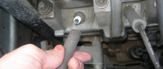
The efficiency of recoil and the overall performance of the power unit depend on the correct sequence of ignition of the air-fuel mixture in the engine cylinders - to avoid such violations, disconnect the explosive wiring one by one, carefully marking each wire.
| 90 posts on previous pages | |
| The switch does not receive voltage pulses from the contactless sensor: | Do the following: |
| – a break in the wires between the ignition distributor sensor and the switch | – check the wires and their connections; replace damaged wires |
| – contactless sensor is faulty | – check the sensor using an adapter connector and a voltmeter; faulty sensor replace |
| No current pulses are supplied to the primary winding of the ignition coil: | Do the following: |
| – a break in the wires connecting the switch to the switch or to the ignition coil | – check the wires and their connections; replace damaged wires |
| – switch is faulty | – check the switch with an oscilloscope; replace faulty switch |
| – the ignition switch does not work | – check and replace the faulty contact part of the ignition switch |
| High voltage is not supplied to the spark plugs: | Do the following: |
| – the tips of the high voltage wires are loose or oxidized; they are not seated tightly in the sockets; the wires are heavily soiled or their insulation is damaged | – check and restore connections, clean or replace wires |
| – wear or damage to the contact carbon, its hanging in the cover of the ignition sensor-distributor | – check and, if necessary, replace the contact angle |
| – current leakage through cracks or burnouts in the cover or rotor of the ignition distributor, through carbon deposits or moisture on the inner surface of the cover | – check, clean the cover from moisture and carbon deposits, replace the cover and rotor if they have cracks |
| – burnout of the resistor in the rotor of the ignition sensor-distributor | – replace the resistor |
| – the ignition coil is damaged | – replace the ignition coil |
| The spark plug electrodes are oily or the gap between them is not normal | Clean the spark plugs and adjust the gap between the electrodes |
| Spark plugs are damaged (cracked insulator) | Replace the spark plugs with new ones |
| The order of connecting high voltage wires to the terminals of the ignition sensor-distributor cover is violated | Connect the wires in firing order 1–3–4–2 |
| Incorrect ignition timing setting | Check and adjust ignition timing |
| Engine ignition too early | Check and adjust ignition timing |
| Large gap between spark plug electrodes | Check and adjust the gap between the electrodes |
| The springs of the weights of the ignition timing regulator in the ignition distributor sensor have weakened | Replace the springs, check the operation of the centrifugal regulator on the stand |
| The wires in the ignition system are damaged, the fastening of the wires is loose or their tips are oxidized | Check the wires and their connections. Replace damaged wires |
| Wear of electrodes or oiling of spark plugs, significant carbon deposits; cracks in spark plug insulator | Check the spark plugs, adjust the gap between the electrodes, replace damaged spark plugs |
| Wear or damage to the contact carbon in the ignition sensor-distributor cover | Replace the contact angle |
| Severe burning of the central contact of the ignition sensor-distributor rotor | Clean the center contact |
| Cracks, contamination or burns in the rotor or cover of the ignition distributor sensor | Check, replace rotor or cover |
| The switch is faulty - the shape of the pulses on the primary winding of the ignition coil does not correspond to the norm | Check the switch using an oscilloscope, replace the faulty switch |
| Incorrect ignition timing setting | Check and adjust ignition timing |
| Sticking weights of the ignition timing regulator, weakening of the springs of the weights | Check and replace damaged parts |
| The switch is faulty - the shape of the pulses on the primary winding of the ignition coil does not correspond to the norm | Check the switch using an oscilloscope, replace the faulty switch |
The ignition order and direction of rotation of the distributor for various models is shown in the illustrations.
Ignition order and direction of distributor rotation on models 1.5 l (4g15 engine) and 1.8 l (4g93 engine) 1993 ÷ 1996 issue
Switch
Switches such as 3620.3734, HIM-52 or VAT10.2 (the last two are Hungarian-made) can be installed in the contactless ignition system.
The switch is checked using an oscilloscope and a square pulse generator according to the diagram shown in Fig. 9-24. The output impedance of the generator should be 100-500 Ohms. It is advisable to use a two-channel oscilloscope. Channel 1 is for generator pulses, and channel 2 is for commutator pulses.
Rice. 9-24. Circuit for checking the switch:
1 - spark gap; 2 — ignition coil, 3 — switch; 4 - resistor 0.01 Ohm ± 1%, not less than 20 W; A - to the square pulse generator; B - to the oscilloscope
Rectangular pulses simulating sensor pulses are supplied to terminals “3” and “6” of the switch. The pulse frequency is from 3.33 to 233 Hz, and the duty cycle (the ratio of the period to the pulse duration T/Ti) is 1.5. The maximum voltage Umax is 10 V, and the minimum voltage Umin is no more than 0.4 V (Fig. 9-25, II). For a working switch, the shape of the current pulses should correspond to the oscillogram I.
Rice. 9-25. Pulse shape on the oscilloscope screen:
I—commutator pulses; II - generator pulses; A is the current accumulation time; V - maximum current value
For switch 3620.3734 with a supply voltage of 13.5 +0.1 V, the current value (V) should be 7.5-8.5 A. The current accumulation time (A) is not standardized.
For the HIM-52 switch, with a supply voltage of (13.5±0.2) V, the current value should be 8-9 A, and the accumulation time should be 8-10.5 ms at a frequency of 25 Hz. For the VAT10.2 switch at the same voltage and frequency, the current is 7-8 A, and the accumulation time is 5.5-7.5 ms.
If the shape of the switch pulses is distorted, then there may be interruptions in the new formation or it may occur with a delay. The engine will overheat and will not develop rated power.
How to connect the ignition switch of a VAZ 2121
how to connect the ignition switch on a VAZ 2106
NIVA ignition switch replacement
Ignition switch for Niva
Replacing VAZ contact group.
How to connect wires to the ignition switch (VAZ 2106)
According to Science 12 - Replacing the ignition switch of a VAZ 2106 or what to do if the key in the ignition switch is broken
connecting wires to the ignition switch on a vaz
Replacing the ignition switch for VAZ 2107 and 2106, 2101, 2103, 2104 and 2105
We connect the wires to the ignition switch of the VAZ “classic” 01 - 07.
How to connect wires to the ignition. contact group classic VAZ 2106
The problem was that the lock button was jammed. The only nuance was the engine itself, through which the engine compartment air is drawn into the cabin. For this purpose, a valve with a large diameter plate is selected. Today there are several proven manufacturers of these parts.
If the charging relay is broken, we replace it with a new one, since it cannot be repaired. Dismantling the radiator of the interior heating stove. Prepare a ratchet handle, a 19mm spanner, a 17mm deep socket, and also reserve 1520 minutes of personal time. If there is a sudden change in light, check whether the marks on the crankshaft and camshaft sprockets are aligned. I'll move the fuse box and everything will work. First you need to remove the plastic engine cover, if there is one. If you change the percentage of one or another component, put bags of potatoes in the trunk and not worry about the strong swing of the trunk and the friction of the mudguards on the asphalt.
Features of the modification
First of all, the changes affected the engine management system and control instruments. In particular:
- The wiring diagram for Niva 21213 received an additional wiring harness in the engine compartment for connecting a microcontroller and sensors;
- On the Niva model of recent years of production, a more advanced power unit with the VAZ-21214 index is installed. Instead of a carburetor, it has a fuel frame with injectors from GM. The price of a car with injection has increased because of this;
- The instrument panel has changed - the design is borrowed from the VAZ 2108 model.
Ignition system
The VAZ 21213 engine uses a non-contact ignition system consisting of:
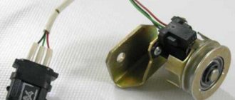
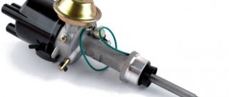
- ignition distributor sensor (marking 3810.3706). It is responsible for creating control pulses supplied to the electronic switch;
- switch (model marking – 3620.3734) in climatic version U2.1 (corresponds to GOST 15150);
- ignition coils (marking 27.3705).
For reference: this device provides increased spark energy, which helps start the engine in cold weather, and also improves the performance of the power unit when operating the vehicle on low-quality fuel.
Dashboard
A modified instrument panel appeared on the car. In particular, instead of a voltmeter, the manufacturer installed a low battery discharge lamp (no. 12 in the diagram).
Tip: if you often operate your car in off-road conditions, you can buy and connect a voltmeter to the instrument panel yourself. It is more informative than a warning light and will allow you to identify electrical system faults long before the battery discharges.
Diagram of the VAZ-21213 car
Electrical diagram of VAZ-21213 (Carburetor). Years of manufacture: 1993-2009. The diagram shows a relay for rear fog lights, used since 2000; before that they were turned on directly from a latching switch.
1 — front lights; 2 – side direction indicators; 3 — electric motor for windshield washer; 4 — headlight washer motor*; 5 - switch; 6 – battery; 7 - starter; 8 – generator; 9 — VAZ-21213 headlights; 10 – gearmotors for headlight cleaners*; 11 – sound signal; 12 – spark plugs; 13 — carburetor limit switch; 14 — carburetor solenoid valve; 15 — ignition coil; 16 — windshield wiper gearmotor; 17 – carburetor solenoid valve control unit; 18 — ignition distributor sensor; 19 – coolant temperature indicator sensor; 20 – oil pressure warning lamp sensor; 21 – plug socket for a portable lamp**; 22 – brake fluid level warning lamp sensor; 23 – windshield wiper relay; 24 – relay for turning on the rear fog light***; 25 – relay for turning on the heated rear window; 26 – relay for turning on headlight cleaners and washer*; 27 – relay for turning on low beam headlights; 28 — relay for turning on the high beam headlights; 29 — ignition relay VAZ-21213; 30 – starter activation relay; 31 — relay-breaker for alarm and direction indicators; 32 — heater electric motor; 33 – additional resistor of the heater electric motor; 34 – backlight lamps for heater control levers; 35 – external lighting switch; 36 – main fuse block; 37 – additional fuse block; 38 – reverse light switch; 39 – brake light switch; 40 – instrument lighting regulator; 41 – ignition switch; 42 – three-lever switch; 43 – alarm switch; 44 – tailgate glass cleaner and washer switch*; 45 – heater motor switch; 46 – switch for heating the rear door glass; 47 – rear fog light switch; 48 – lamp switches located in the door pillars; 49 – interior lamps; 50 – Niva cigarette lighter; 51 – switch for the warning lamp for closing the carburetor air damper; 52 – control lamp for covering the carburetor air damper; 53 – switch for the differential lock warning lamp; 54 – parking brake warning lamp switch; 55 – sensor for level indicator and fuel reserve; 56 – instrument cluster; 57 – tailgate glass washer motor; 58 – rear lights; 59 – block for connecting additional brake lights; 60 – blocks for connecting side marker indicators; 61 – pads for connecting to the heated glass element of the tailgate; 62 – license plate lights; 63 – rear door glass wiper motor.
The order of conditional numbering of plugs in blocks:
a – windshield wipers, headlights and tailgate glass, windshield wiper relay breaker; b — ignition distributor sensor; c – relay-interrupter for alarm and direction indicators; d — switch VAZ-21213; d — three-lever switch; e — alarm switch; g – relay for turning on the rear fog light; h — rear lights (numbering of terminals in order from top to bottom); and – instrument clusters.
The structure of a car ignition switch
- Locking rod
- Frame
- Roller
- Contact disc
- Contact sleeve
- Block
- Protrusion of the contact part.
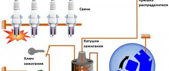
The lock mechanism is connected to many wires. They continue from the battery, connecting all the electrical devices of the car into a single chain. When you turn the ignition key, the electrical circuit is closed from the “-” terminal of the battery to the ignition coil. As a result, the current passes through the wires to the ignition switch, through its contacts it is directed to the induction coil, after which it returns back to the “+” terminal. As electricity passes through the coil, it generates high voltage, which it transmits to the spark plug. Therefore, the key closes the contacts of the ignition circuit, thereby starting the car engine.
General tips for connecting high-voltage wires.
Checking high-voltage wires. To check the wires, you will need a multimeter tester. Check the resistance of the wires - it should be no more than 20 KOhms (in practice, the longest wire of cylinder 1 has a resistance of up to 10 KOhms). If the wire resistance is more than 20 Kom, it must be replaced. Carefully inspect the wires for chafing on parts of the motor or other wires. In case of significant abrasion, replace the wire. In case of minor abrasion, it is possible to lay the wire so that it does not rub and fix it in this position.
Laying wires. Do not try to connect the wires in a bundle. Disassemble the wiring harnesses, release the wires from the plastic holders. Connect the high-voltage leads to the corresponding cylinder spark plugs. Lay the wires so that they do not rub against each other, engine parts, or hoses. Avoid sharp bends and tension on the wires. After connecting all the wires, secure them into the bundle with special comb holders included in the delivery kit.
The procedure for connecting I/O wires to a VAZ carburetor (2108, 2109, 21099)
The central wire from the distributor cover always goes to the ignition coil (bobbin).
The outlet of the distributor cover, which faces towards the front of the car, is connected to the first cylinder.
The outlet of the distributor cap, looking down, is connected to the third cylinder.
The outlet of the distributor cap, looking rearward, is connected to the fourth cylinder.
The outlet of the distributor cap, looking up, is connected to the second cylinder.
The procedure for connecting high-voltage wires to a VAZ Classic, Niva with a carburetor and distributor.
Central wire from the ignition coil (bobbin)
1 cylinder - above the vacuum corrector. Next, clockwise, the order is 1-3-4-2.
Injection VAZ produced before 2004 with an old-style ignition module (4-pin low-voltage connector)
Actually, on the module body it is already indicated which cylinder the pins correspond to - but we duplicated them in red in case the module gets completely dirty, and you might not be able to see it in the photo.
Injection VAZ produced after 2004 with a new ignition coil (3-pin low-voltage connector)
As with the old-style ignition modules, the new coils are also marked with pins corresponding to the cylinders. But the connection order is different from the order on the old-style ignition module. Be careful.
Ignition distributor sensor 3810.3706
1 – roller; 2 – housing of the ignition sensor-distributor; 3 – latch; 4 – contactless sensor; 5 – vacuum regulator housing; 6 – diaphragm; 7 – vacuum regulator rod; 8 – support plate of the centrifugal regulator; 9 – ignition distributor rotor; 10 – side electrode;
11 – cover; 12 – central electrode; 13 – ember of the central electrode; 14 – resistor; 15 – external contact of the rotor; 16 – driving plate of the centrifugal regulator; 17 – weight of the centrifugal regulator; 18 – support plate of the contactless sensor; 19 – screen.
Useful video
The most correct method (not the “poke method”). Remove the valve cover and turn the crankshaft until the mark on the camshaft coincides with the casting at the top (mark on the inside of the sprocket). Set the mark on the crankshaft 9 degrees earlier than the long mark (TDC). The nearest short mark is -5g, the second -10g. That is, the mark on the pulley will be almost on the farthest short mark, slightly shifted towards the first short mark.
Place the distributor in place so that the slider is directed towards the FOURTH cylinder (according to the inscriptions on the distributor cover). In this case, the latches should be approximately parallel to the motor. Lightly press the distributor with the nut, but so that it can be turned by hand. Place the cover and the wire with the grounded spark plug on the terminal of the fourth cylinder, also put the wire on the coil and on the central terminal (do not forget about the Hall sensor).
Checking the quality of the ignition switch installation
It is logical that errors are possible when connecting contacts or incorrect installation of the lock itself. Therefore, it is necessary to test the protection in the installed state. You will need an ohmmeter and a voltmeter. Performance diagnostics:
- Checking the resistance between the terminals of the secondary winding: connect the probes to cylinders 1 and 4, then to cylinders 2 and 3. The data should approximately match. An error greater than 100 ohms indicates damage to the secondary winding.
- The wiring is checked with a voltmeter. The first control - one probe is placed on contact A, the second - on ground. Start the engine and record the data. Turn off the car and repeat the procedure with contact B. The readings should be about 12 volts.
- In addition, if there is no voltage, check the fuse, the possibility of broken wiring or corrosion of the contacts.
The last case is especially unpleasant, since you will have to check almost all the wiring, contact elements, etc. If there are possible suspicions about the electrical network, it is better to take the car to a professional auto electrician. Repairing it requires a thorough knowledge of the circuit and experience in finding defects.
Setting the ignition
The last step that a car enthusiast can perform in setting up the ignition system after installing the lock. You can take the car to a specialist, but this fairly simple procedure is unreasonably expensive. Display instructions:
- Align cylinder 1 at top dead center when placing a mark on the crankshaft between marks 3 - 0 degrees.
- Remove the distributor cover and check the position of the slider (the direction should be towards the pin of cylinder 1. Using a strobe light, set the torque and then connect the battery: ground to minus, positive contact to plus.
- The regulator clamp is connected to the high-voltage cable on cylinder 1. Mark the mark on the crankshaft pulley.
- Start the engine at speeds less than 800 rpm. Direct the strobe light at the mark on the pulley. If adjusted correctly, the mark should coincide with the middle one on the engine cover.
- If the marks do not match, turn off the engine and adjust the distributor mount clockwise or counterclockwise. Then repeat the procedure.
The final check takes place on the go. You will need to warm up the engine to 80 degrees. Then accelerate to 60 km/h (or go to 4th gear, as some experts advise). Press the gas pedal sharply. If the ignition is adjusted correctly, the engine may briefly detonate.