The Hall sensor of the VAZ 2107 is one of the most necessary components in the car’s ignition system. If it fails, then interruptions in the operation of the power plant may begin and it is quite possible that the car will stop completely.
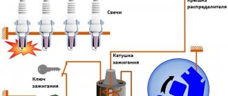
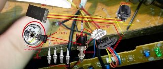
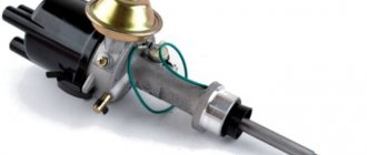
The Hall sensor on the VAZ 2107 is a control device that is a camshaft controller, which is installed near the distributor and guarantees its correct operation. The breaker-distributor shaft has a special plate in the shape of a crown. This plate has special slots, and there is a magnet on the camshaft controller. As the camshaft rotates, metal vanes enter the controller space. As a result, a pulse voltage is generated that goes to the ignition coil, and it is converted into an increased voltage. The ultimate goal is the spark plugs.
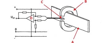
Ignition operation diagram
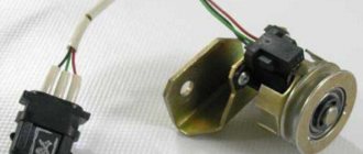
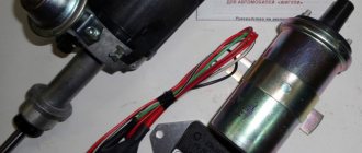
It should be noted that the VAZ 2107 camshaft controller has only 3 terminals. One is connected to the minus, and the other supplies a voltage of six volts, the 3rd one transmits the impulse directly to the switch.
VAZ Hall sensor
How to recognize the problem
If you suspect that the Hall controller on a VAZ has begun to malfunction, before replacing it you need to make sure that it is the problem. This is determined by the following criteria:
- the power unit starts with difficulty or does not start at all;
- the engine runs jerkily, the speed is uneven;
Power point
- jerking when driving at high speeds;
- unpredictable engine operation - it can stop at any time.
Where is?
You may be interested in: Fellowes PrivaScreen: a cure for curiosity
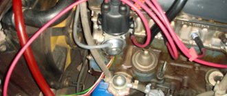
On VAZ-2109 cars with a carburetor, the Hall sensor is mounted in the ignition distributor housing. It works due to the fact that the distributor has a half-cylinder-shaped screen in its design. Its side surface has windows - slots. When the metal part of this half-cylinder passes near the active part of the sensor, an impulse is sent to the electronic switch. As soon as a window appears on the device, the pulse is interrupted.
The Hall sensor of the VAZ-2109 is supplied with a voltage of 12 V, but the current consumption is extremely low. It is only enough to open the semiconductor located in the switch. The latter amplifies the signal and feeds it to a coil, which is a step-up transformer. As a result, more than 20 kV is obtained from 12 Volts. True, the current decreases significantly. Therefore, a spark does not pose a danger to human life. But if you get such an electric shock, then it’s still not very pleasant.
Verification method
Experts recommend the following methods for checking the Hall sensor of a VAZ family car before replacing it:
- The easiest and most reliable is to borrow a proven or new sensor from someone and install it to replace your own. If the engine operation has returned to normal, then you need to go to the store and buy a new one.
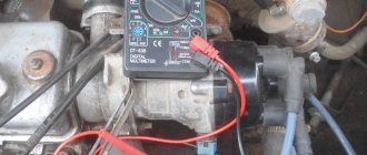
- The second method is to measure the output voltage using a tester. A working sensor produces a voltage of 0.4-11 Volts.
- The next option can be called an imitation of the work of the Hall controller. It is not difficult to master; you need to pull out the block with 3 plugs from the controller itself. Next, turn on the ignition and connect the 3rd and 6th outputs. If there is a spark, then most likely the cause of interruptions in the system should be looked for in another unit, but not in the sensor.
DH malfunctions
Malfunctions of the VAZ-2106 engine can be caused not only by the failure of the diesel engine. Therefore, identifying the causes of failures is carried out in stages, checking the power supply, the condition of the coil, wires, contacts, etc. Only by eliminating other causes can we conclude that the Hall sensor is unusable.
Deterioration in the performance of the VAZ-2106 DH is characterized by the occurrence of the following malfunctions:
- fuel consumption increases sharply;
- the engine choke while the car is moving and may stall;
- the engine does not start.
After all options for the reasons for the malfunction of the internal combustion engine (ICE) have been checked, we move on to checking the functionality of the Hall sensor.
Replacement
If you are convinced that the problem is with the Hall sensor, then you can replace it yourself. This is not difficult and any motorist can handle it if desired. There is no point in overpaying the service station technicians; you can check it yourself and handle the replacement yourself.
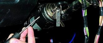
Tools
You will need this screwdriver
Stages
It is advisable to carry out work in a well-lit room.
Correct connection of the block
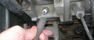
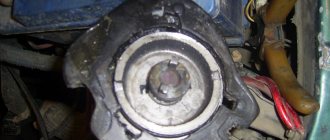
- First of all, it is necessary to remove the distributor itself from the car and then unscrew the cover.
- Next, pull up a little and remove the slider.
- Remove the plastic cover.
- The plug is secured with a bolt and needs to be unscrewed.
- Let's take him out.
- The sensor plate is held on by bolts that need to be unscrewed.
- The vacuum corrector is fixed with bolts, we also unscrew them.
- Remove the retaining ring.
- We remove the traction and the corrector itself.
- To get the wires you need to move the clamps apart.
- Remove the support plate.
- Now all that remains is to unscrew a couple of bolts and remove the Hall sensor.
- We install a new one.
- Assembly work is performed in reverse order.
Important! If any signs of breakdown occur, do not delay repairs. Check the Hall controller immediately and replace it if necessary.
As you can see, everything is very, very simple. It is worth spending just an hour of your time to save several thousand rubles, which you will have to pay to the service station.
Summary
The Hall sensor reads the pulses and sends a signal to the switch. Contactless ignition is much more efficient than cam ignition. Engine performance has noticeably improved, and there is no carbon deposits on the contact group. If the hall sensor on your VAZ 2107 (carburetor or injector) is malfunctioning, then the malfunction can be determined by the symptoms of defective engine operation or through simple diagnostics. Replacing the DH is easy to do yourself. To do this, it is recommended to prepare a well-lit garage with a workbench and a simple set of tools.
Self-check video
This video shows how to properly check the Hall sensor of a VAZ car.
How to check and replace sensor on a VAZ 2107
?
Sensor
Hall VAZ
2107
is one of the most necessary components in the car ignition system. If it fails, then interruptions in the operation of the power plant may begin and it is quite possible that the car will stop completely.
Sensor
Hall on the VAZ
2107 is a control device, which is a camshaft controller, which is installed near the distributor and guarantees its correct operation.
The breaker-distributor shaft has a special plate in the shape of a crown. This plate has special slots, and there is a magnet on the camshaft controller. As the camshaft rotates, metal vanes enter the controller space. As a result, a pulse voltage is generated that goes to the ignition coil, and it is converted into an increased voltage. The ultimate goal is the spark plugs. Ignition operation diagram
2107 camshaft controller has only 3 terminals. One is connected to the minus, and the other supplies a voltage of six volts, the 3rd one transmits the impulse directly to the switch.
VAZ sensor
Hall
KEY-DOP
Operating principle of DH
The ignition distributor shaft is splined into a helical gear, which in turn is connected to the crankshaft sprocket. A change in the openings of the cup, falling into the “field of view” of the sensor, causes fluctuations in the electromagnetic field, which is reflected by a proportional change in the voltage in the signal wire, “notifying” the switch about this. This, in turn, synchronously supplies high voltage current to the central wire of the distributor cover, from where the current enters the spark plugs through the slider and wires.
This contactless ignition system is certainly more advanced than a distributor with a contact breaker. And yet, compared to modern electronic ignition modules, the BSG VAZ-2106 is more susceptible to breakdowns due to the presence of moving parts. It is they who most often become the cause of malfunctions in its ignition system.
Verification method
Experts recommend the following methods for checking the Hall sensor of a VAZ family car before replacing it:
- sensor
from someone and install it to replace your own. If the engine operation has returned to normal, then you need to go to the store and buy a new one. - The second method is to measure the output voltage using a tester. working sensor
produces a voltage of 0.4-11 Volts. - The next option can be called an imitation of the work of the Hall controller. It is not difficult to master; you need to pull out the block with 3 plugs from the controller itself. Next, turn on the ignition and connect the 3rd and 6th outputs. If there is a spark, then most likely the cause of interruptions in the system should be looked for in another unit, but not in the sensor.
KEY-DOP
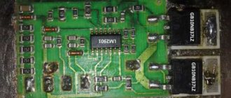
Diagnostics of malfunctions of the ignition module of injection VAZ 2107
The ignition of the injection VAZ 2107 is completely electronic and is considered quite reliable. However, problems can arise with it too. The module plays an important role in this.
Signs of a malfunctioning ignition module
Symptoms of a faulty module include:
- the Check engine warning light on the dashboard lights up;
- floating idle speed;
- engine tripping;
- dips and jerks during acceleration;
- change in sound and color of exhaust;
- increased fuel consumption.
However, these signs can also appear in case of other malfunctions - for example, in case of problems with the fuel system, as well as in case of failure of some sensors (oxygen, mass air flow, detonation, crankshaft position, etc.). If the engine starts to operate incorrectly, the electronic controller puts it into emergency mode, using all available resources. Therefore, when the engine operation changes, fuel consumption increases.
In such cases, you should first of all pay attention to the controller, read information from it and decipher the error code that has occurred. To do this, you will need a special electronic tester, available at almost any service station.
If the ignition module fails, error codes in engine operation may be as follows:
- P 3000 - no sparking in the cylinders (for each cylinder the code may look like P 3001, P 3002, P 3003, P 3004);
- P 0351 - break in the winding or windings of the coil responsible for cylinders 1–4;
- P 0352 - a break in the winding or windings of the coil responsible for 2–3 cylinders.
At the same time, the controller can produce similar errors in the event of a malfunction (break, breakdown) of high-voltage wires and spark plugs. Therefore, before diagnosing the module, you should check the high voltage wires and spark plugs.
Main malfunctions of the ignition module
The main malfunctions of the VAZ 2107 ignition module include:
- a break or short to ground in the wiring coming from the controller;
- lack of contact in the connector;
- short circuit of the device windings to ground;
- break in the module windings.
Checking the ignition module
To diagnose the VAZ 2107 injection module, you will need a multimeter. The verification algorithm is as follows:
- Raise the hood, remove the air filter, find the module.
- We disconnect the block of the wiring harness coming from the controller from the module.
- We set the multimeter to measure voltage in the range 0–20 V.
- Without starting the engine, turn on the ignition.
- We connect the negative (usually black) probe of the multimeter to ground, and the positive one to the middle contact on the harness block. The device must display the voltage of the on-board network (at least 12 V). If there is no voltage or it is less than 12 V, the wiring or the controller itself is faulty.
- If the multimeter shows a voltage of at least 12 V, turn off the ignition.
- Without connecting the connector with wires, disconnect the high-voltage conductors from the ignition module.
- Switch the multimeter to resistance measurement mode with a measurement limit of 20 kOhm.
- To check the device for an open circuit in its primary windings, we measure the resistance between contacts 1a and 1b (the outermost ones in the connector). If the resistance of the device tends to infinity, there is indeed an open circuit in the circuit.
- We check the module for breaks in the secondary windings. To do this, we measure the resistance between the high-voltage terminals of the first and fourth cylinders, then between the terminals of the second and third cylinders. In operating condition, the module resistance should be about 5–6 KOhm. If it tends to infinity, the circuit is broken and the module is faulty.
Stages
It is advisable to carry out work in a well-lit room.
Correct connection of the block
- First of all, it is necessary to remove the distributor itself from the car and then unscrew the cover.
- Next, pull up a little and remove the slider.
- Remove the plastic cover.
- The plug is secured with a bolt and needs to be unscrewed.
- Let's take him out.
- The sensor plate is held on by bolts that need to be unscrewed.
- The vacuum corrector is fixed with bolts, we also unscrew them.
- Remove the retaining ring.
- We remove the traction and the corrector itself.
- To get the wires you need to move the clamps apart.
- Remove the support plate.
- Now all that remains is to unscrew a couple of bolts and remove sensor
. - We install a new one.
- Assembly work is performed in reverse order.
Self-check video
This video shows how to properly check sensor of a VAZ car.
When the Hall sensor on a VAZ 2107 breaks down, this makes it impossible to continue driving. The Hall sensor belongs to the category of key parts of a contactless ignition system, and if this part begins to fail, the switch will stop sending impulses to produce a spark. To troubleshoot the problem, you need to understand in detail the purpose and operation of the device.
Device
When switching to a non-contact ignition system (BSI), the distributor was improved. The design of the ignition distributor itself was changed, and a switching device was added - an electronic ignition control unit. The cover and slider remained the same, but the place of the breaker was taken by a Hall sensor and a synchronization cup (screen with slots) was installed coaxial with the shaft.
The DH is attached with two screws to the bearing holder under the distributor cover. Three wires stretch from it through the connector to the switch: two of them supply power (+ and 0), and the third transmits a control signal to the switch. The sensor consists of two parts: a meter and a magnet. Between them there is a side of a rotating cup with 4 cutouts (according to the number of engine cylinders).
Why is a Hall sensor needed and how does it work?
The device of the contactless ignition system of the VAZ 2107 car has such an element called a Hall sensor. Its fundamental purpose is the ability to detect the angle of the crankshaft and camshaft of the power unit. The Hall sensor is not installed on injection models of sevens, it is installed only on carburetor ones.
According to the value of this device, voltage pulses are supplied to the spark plugs. The functioning of this element is based on increasing the voltage in the cross-section of a wire placed in a magnetic field. The element is connected by three terminals, two of which provide power supply (plus and minus), and the third contact is intended directly for supplying a signal. The device received this name due to a special effect that was identified by scientist Hall. In the distributor on the shaft there is a plate that is part of the control of the device controller.
When the motor operates, the metal in the slots alternately changes, and the magnet, which is located inside the controller, begins to be excited by oscillations of the magnetic field. In this case, the controller generates voltage pulses issued by the switch and supplied to the coil. The coil, in turn, raises the voltage to a high value and transports it one by one through armored wires to the spark plugs. Knowing the operating features, you need to deal with the malfunctions, but before that it is important to note that the Hall sensor on the VAZ 2107 is located in the distributor under the cover. To replace it, you will need to disassemble the distributor.
Basic sensor malfunctions
Any part on a car sooner or later begins to malfunction, and the Hall sensor is no exception, even though it has the simplest design. Its breakdown is detected by detecting the following defects:
- Inability to start the engine.
- Unstable and unstable operation of the motor.
- The occurrence of jerks.
- The engine begins to stall.
- The appearance of the detonation effect.
If the above symptoms appear, then there is no need to rush to change the Hall sensor, since similar phenomena can also occur due to other breakdowns of the ignition and fuel supply system. To verify that the device is faulty, you will need to perform a suitability test.
Check Features
The BSZ contactless ignition on the VAZ 2107 has a Hall sensor, the serviceability of which determines the normal operation of the internal combustion engine. If you suspect that it is faulty, then you need to check the Hall sensor. To do this, there are different ways on the basis of which one can draw a conclusion about the suitability of the element.
The following two methods are used to check an element:
- The simplest test method is to install a known-good element. If the signs of malfunctions immediately disappear, it means that the breakdown was detected correctly and successfully repaired. The disadvantage of this method is that you must first purchase a working element.
- Use a multimeter to check the voltage at the sensor output. The device switches on the voltage measurement mode, after which the value at the device output is measured. The value should be between 0.4 and 11 Volts, and if this is not the case, the element should be replaced.
- Simulation of device operation. The test diagram is as follows - the element terminal should be removed from the connector, and then turn on the ignition. Now we begin to simulate the operation of the Hall sensor, for which contacts 3 and 6 of the switch output are connected. If sparking occurs, the element must be replaced.
Scheme and principle of operation of BSZ
All elements of the system are connected to each other and to the engine as follows:
- The distributor shaft rotates from the motor drive gear;
- The Hall sensor installed inside the distributor is connected to the switch;
- the coil is connected by a low voltage line to the controller, a high voltage line to the central electrode of the distributor cover;
- high-voltage wires from the spark plugs are connected to the side contacts of the main distributor cap.
The threaded clamp “K” on the coil is connected to the positive contact of the ignition switch relay and terminal “4” of the switch. The second clamp marked “K” is connected to contact “1” of the controller, and the tachometer wire also comes here. Terminals “3”, “5” and “6” of the switch are used to connect a Hall sensor.
The algorithm looks like this:
- After turning the key in the lock, voltage is supplied to the electromagnetic sensor and the first winding of the transformer. A magnetic field arises around the steel core.
- The starter rotates the engine crankshaft and distributor drive. When a screen slot passes between the sensor elements, a pulse is generated and sent to the switch. At this moment, one of the pistons is close to the top point.
- The controller, through a transistor, opens the circuit of the primary winding of the coil. Then a short-term pulse of up to 24 thousand volts is formed in the secondary, traveling along the cable to the central electrode of the distributor cover.
- Having passed through a moving contact - a slider directed towards the desired terminal, the current flows to the side electrode, and from there through the cable to the spark plug. A flash forms in the combustion chamber, the fuel mixture ignites and pushes the piston down. The engine starts.
- When the next piston reaches TDC, the cycle repeats, only the spark is transferred to the other spark plug.
For optimal combustion of fuel during engine operation, a flash in the cylinder should occur a fraction of a second earlier than the piston is in the maximum upper position. For this purpose, the BSZ provides for advance of spark formation by a certain angle. Its value depends on the crankshaft speed and the load on the power unit.
- Replacing lamps in the dashboard of a VAZ 2107
The advance angle is adjusted by the switch and the vacuum unit of the distributor. The first reads the number of pulses from the sensor, the second operates mechanically from the vacuum supplied from the carburetor.