Possible malfunctions: signs and causes
The starter is designed to start the power unit. This is an electromechanical device, so failures can be classified as electrical or mechanical.
Electrical problems are mainly related to the power supply. The cause may be a discharged battery, damaged wiring, interturn short circuits, burnt or oxidized contacts. To identify electrical faults, you need to know how to ring the starter. Mechanical failures occur mainly after long-term use, during which parts wear out and become unusable, as well as as a result of mechanical damage.
Mechanical damage can be caused by electrical problems. The parts of the starting unit experience heavy loads, especially during frosts, since the device has to deliver more power and a strong current passes through it.
The most vulnerable components:
- brushes,
- bushings and armature corrector,
- nickels,
- fork,
- gear,
- traction relay,
- damper spring.
Mechanical breakdowns are indicated by extraneous noise, unpleasant odor, and untimely operation.
The following are symptoms and causes of starter failure:
- Untimely response. In this case, the electric motor rotates constantly, but a metallic grinding noise is heard when starting. The cause may be a malfunction of the damper spring, wear of the gear or bushing. The exact cause can only be determined by removing and disassembling the assembly.
- The starter rotates constantly, but the crankshaft does not turn. There are no extraneous sounds. The cause is most likely a broken bushing.
- When starting, the trigger mechanism does not work. You need to gently tap the starter from behind with a hammer or other object; if the engine starts, it is possible that the brushes are very worn. They need to be replaced.
- After starting the engine, a metallic buzzing sound is heard. In this case, you must immediately turn off the engine. Possible reasons: the fork or gear is jammed, the traction relay is stuck. The exact cause can be determined after removing and disassembling the unit.
- The solenoid relay clicks, but the device does not operate. The cause may be insufficient battery charging. The incoming voltage is enough to trigger the traction, but the nickels are not closed using the contact plate, and power is not supplied to the electric motor of the unit. If the voltage at the battery terminals is normal, then it is possible that there is no voltage on the power cable or the coins are burnt.
- When the battery is fully charged, the starter rotates slowly. It is possible that the bushings are worn out or there is contamination in the electric motor.
- If burning is heard during startup, then the traction relay winding may burn out; more rarely, the armature windings will burn out. This entails overheating of the wires going to the device.
- The traction relay does not operate, the starter does not start. There may be problems with the electrical network. You should check the integrity of the wiring, the correct operation of the unit and other components included in the electrical network.
If the starting unit stops working, you should diagnose it, identify the parts that have become unusable and replace or repair them (author of the video Auto Electrician HF).
What rules for using a starter should be followed to make it last longer?
The car owner can extend the life of the starter subject to the following conditions:
- Keep the engine compartment dry. The absence of moisture will not allow pockets of corrosion to appear and develop on the wires and components of the starter.
- Monitor the insulation on the starter wires and terminals. Damaged wiring leads to loss of current and operation of the electric motor with overload.
- On cars with a manual transmission, start the engine with the clutch depressed, which reduces the load. This is especially true when starting at low air temperatures.
- Avoid contact of the starter with engine oil, fuel or coolant.
- Continuous operation of the starter for more than 10 seconds is prohibited. At least 30 seconds must pass between starting attempts, which is necessary for cooling the electric motor and correct operation of the battery.
- The starter cannot be used to move the vehicle even a short distance.
- Avoid driving through deep puddles.
- Monitor the voltage at the battery terminals.
- Do not turn on the starter while the engine is running. A number of cars use a protective relay that prevents the starter from being turned on when the engine crankshaft is rotating.
Following the recommendations allows you to increase the service life of the starter without repairs to 120-150 thousand km or more.
Signs of a faulty starter
Electrical failures in the starter usually occur due to network overloads. This fact can be detected by short circuits to ground, in the winding of the armature or magnetic coil, as well as in the coils of the magnetic switch control components. The carbon brushes and commutator operate in a highly stressed environment and break down even more often than the generator.
Troubleshooting requires a multimeter and a clamp meter. The starter has several parts, the breakdown of each of them leads to a general failure. To check such components, for example, the armature, brushes and windings, you will need to remove it from the car, disassemble it and test it with a multimeter. Some parts can be tested without removing the starter.
Important! Before checking the starter with a multimeter, you need to be sure that: the battery is fully charged and working properly; the starter receives full current from the battery and from the ignition switch; that the electrical wires and grounding line are in good working order.
The main signs of a broken car starter:
- When the ignition key is turned, the car does not start.
- When you turn the ignition key, you can hear a click, but the engine does not work.
- After turning the ignition key, the engine starts, but slowly.
Why do you need a starter and its design features?
A starter (from the English word start - to begin) is a mandatory unit for starting the engine, which forcibly rotates the crankshaft flywheel to the speed necessary for independent operation.
It is a 4-pole DC electric motor that takes energy from a battery. The starter is necessary to start the engine of any vehicle and receives power from the battery when the key is turned in the ignition.
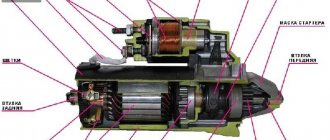
Main components of the starter:
- housing - a cylinder-shaped steel part in which the winding and cores are located;
- anchor - has the shape of an axis and is made of high-strength steel, collector plates and windings are fixed in it;
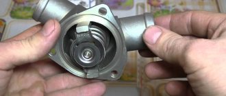
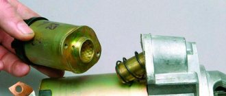
- a solenoid relay that supplies power to the starter when the key is turned in the ignition and pushes out the bendix;
- brushes and brush holders - supply the necessary voltage to the armature commutator unit, increasing the motor power when the engine spins up;
- drive gear and bendix (overrunning clutch).
Despite the huge range of electric motors, there are only two types, distinguished by the presence of a gearbox.
The most modern version of the electromagnetic motor is the gear motor, the main advantages of which include the ability to operate even with a low battery charge and the presence of permanent magnets that reduce problems with the winding.
The main disadvantages of such a unit are the low strength of the gear and the impossibility of repair, which leads to an expensive purchase in the event of a breakdown.
Starters that do not contain a gearbox in their design directly act on the rotating gear.
The main advantages of this type of starter are:
- simultaneous engagement of the flywheel with the gear, allowing you to start the internal combustion engine as quickly as possible;
- durability and long-term operation;
- the ability to independently repair breakdowns and the availability of necessary spare parts in almost any auto shop;
- practically independent of the influence of electric current, which reduces the possibility of breakdowns.
The disadvantages of gearless starters include:
- difficulty starting in extreme cold;
- significant mass of the unit;
- high energy consumption, leading in some cases (if there are faults in the starting system or other components) to a strong discharge of the battery and the impossibility of starting the internal combustion engine without recharging;
- quite high prices for spare parts.
How to test a starter with a multimeter
Checking the starter resistance using a multimeter is the main method for diagnosing failures of the car's starting system. A high-resistance starter will drain the battery faster than the alternator can recharge it. In most cases, to test the stator, it must be disassembled.
Starter internals:
- An outer housing that supports the relay and allows it to be attached to the transmission.
- A toothed head (bendix) that must engage with the motor flywheel to transmit movement. Until the ignition key is turned, the relay will not move.
- The rotor is an element that constantly rotates and is in contact with the brushes.
- Stator.
- Brushes.
- Electromagnetic solenoid.
Important! Before testing the armature windings, you need to take into account the fact that their resistance is very small, which a conventional multimeter is not capable of establishing. In this case, the windings ring to indicate the presence of a break. The collector lamellas need to be ringed one by one, or their performance is checked by the voltage drop. In these cases, it must be equal when current is supplied, approximately 1 A.
Electrical resistance
To perform this type of test, set the multimeter to ohmmeter mode. To test the starter relay, place one test lead on a terminal in the ignition circuit and the other on ground. When the starter relay is working properly, R=5 Ohms and below. If the user finds a resistance on the multimeter scale that does not meet the conditions of R=5 Ohms, the relay is faulty and needs to be replaced.
Similarly, you can find out the resistance by installing the red probe of the device on the ignition line terminal, and the black probe on the ground terminal. The voltage mode with a range of 20 V is turned on. The car ignition is started, and the tester readings are checked. If it does not correspond to 12 V, then the starter relay must be replaced.
Voltage drop
To check the voltage drop in the starter, you will need to invite an assistant. The measuring device is set to constant mode with a 20 V scale. Connect the red probe of the device to the red terminal of the battery wire, and the black one to the ignition circuit. Ask an assistant to turn the ignition key and observe the multimeter reading. The voltage drop for the operating starter relay cannot be higher than 0.2 V.
Important! If the voltage drop is higher than 0.2 V, there may be a continuity problem with the starter relay. In this case, experts recommend carefully inspecting the wiring and removing oxidation from the terminals. If this does not help, the starter will need to be replaced.
Starter winding
The starter winding can be checked for integrity. To do this, it is measured with a multimeter in ohmmeter mode.
Before checking the starter winding, the device is connected between the winding terminals and the starter housing. The resulting R must be no higher than 10 kOhm. The rotor winding between the collector plate and the core is tested in the same way.
Starter brushes
This check is performed with the starter removed. Check for short to ground. Switch the meter into ohmmeter mode between the main plate and the brush holder. If there is no closure, R must equal infinity.
Important! After dismantling the brush assembly, it is necessary to conduct an external inspection of the armature, stator, rotor and brushes.
Since during operation of the bushings there may be a drop in current during startup, the motor will operate unstably, and damage will appear on the commutators, which will destroy the brushes.
Bushings that have a broken fit create conditions for armature misalignment and uneven wear of the brushes. This increases the probability of the formation of an interturn short circuit in the electrical winding.
Starter armature
Testing the starter armature with a multimeter is performed after the initial armature test has been completed. It is carried out by supplying 12 V voltage from the battery, bypassing the relay, with a direct connection to the starter. If it starts to work when the voltage is directly applied, then the reason for the failure to start the engine is wear of the brushes. Next you will need to disassemble the anchor and make a visual inspection of its external condition. And only after this you need to check the starter armature with a multimeter in ohmmeter mode.
During operation, car enthusiasts can often find damage to the winding by external inspection. For example, chips are found between the collector lamellas or burnt lamellas are found, uneven wear of structures or pinouts are found.
Important! The main failure in the operation of the armature is a breakdown of the winding housing. It can be easily diagnosed with a multimeter, and when a short circuit occurs between the windings and the multimeter cannot cope, you need a special meter.
Interturn closure of armature
To check the armature, we will use a special device, which represents a transformer with a cut-out core. When we place the armature in this gap, its winding begins to act as the secondary winding of a transformer. Moreover, if there is an interturn short circuit on the armature, the metal plate, which will be located on top of the armature, will vibrate or be magnetized to the armature body due to local oversaturation with iron.
We turn on the device. For clarity, we specially closed two lamellas on the collector to show how diagnostics are performed. We place the record on the anchor and immediately see the result. Our record became magnetized and began to vibrate. We turn the armature, the coils shift, and the plate stops vibrating.
Now let's remove the slat short circuit to check. We repeat the check and see that the armature winding is working properly, the plate does not vibrate in any places.
How to check the starter for functionality without removing it from the car
To begin with, it would be nice to find the location of this device in the wilds of the engine compartment. Usually, access to it is somewhat limited, but you can always reach it with your hand. At the same time, there is no urgent need to crawl under a dirty car and get your clothes dirty. It is also a good idea to check whether the battery is charged. It is likely that the low beam was left on and the battery was discharged. If everything is in order with the battery, then you need to find a voltmeter in the tools. If something happens, it will be easy to buy such a device in an auto supply or electronics store, and it costs very affordable.
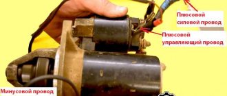
So, a thick braided wire from the battery goes to the large bolt on the starter. This is the positive terminal of the solenoid relay. You need to put the “crocodile” of the positive (red) wire of the voltmeter on it. We connect the black wire to the ground of the car in the same way. Now you should ask someone to turn the ignition key. In this case, the needle on the scale should show 12 V, and the starter itself should begin to make characteristic clicks. If the voltage does not reach the indicated value, the problem is either in the battery or in the ignition switch (switch). Even if the starter clicks but there are less than 12 volts, there is a clear problem worth fixing.
The most effective way to check the starter for functionality without removing it from the car will require a longer screwdriver with a good plastic (rubberized) handle. You need to disconnect the wire coming from the ignition switch from the solenoid relay. Use the metal part of the screwdriver to carefully short-circuit the positive terminal of the relay with the bolt from which the wire was just disconnected. This will allow current to be supplied directly from the battery to the relay, and the car can start from this. If it works, this means that the lock is faulty and requires replacement, or the solenoid relay is worn out.
Video “Repairing the starter unit at home”
How to properly repair a device and what nuances need to be taken into account - learn from the video (author - AUTO RES channel).
The ability to start the engine by turning the ignition key from inside the car and without much physical effort can easily be considered one of the most significant achievements of designers in terms of improving the consumer qualities of a car. However, sometimes it happens that you cannot start the car with an electric starter. The reasons for such an unpleasant event are varied, but the list of the most likely among them includes a malfunction of the solenoid relay. A savvy car enthusiast is able to quickly localize and diagnose such a breakdown on his own, after which he can carry out repairs and restore the vehicle to normal operation without contacting a service center and with minimal financial costs. An assistant will be required to perform some of the checks.
Simple check on the car
Initially, it is important to find the unit itself among the elements of the engine compartment. In most cases, the starter housing can be easily accessed from above by opening the hood. Before the procedure, you need to check the condition of the battery.
The voltage of a fully charged battery that is not under load is 12.6-12.9 Volts. After this, you can go directly to checking the starter. To do this you will need a voltmeter and a long screwdriver with a rubberized handle.
This can be done in two ways.
Method No. 1
Here we need a voltmeter and an assistant.
The check must be carried out in the following order:
- Locate the positive terminal of the solenoid relay on the starter unit. It looks like a large bolt with a thick braided wire attached to it.
- Connect the red wire of the voltmeter to it.
- Attach the black cable of the device to the ground of the car.
- After this, ask an assistant to turn the ignition key. At this time, the voltmeter should show 12 volts, and the starter should make characteristic knocking noises. If the voltage is lower, then the problem is most likely in the battery or ignition switch.
Method No. 2
To check in another way, you will need a long screwdriver.
Here you need to follow the following algorithm:
- Disconnect the wire that comes from the ignition switch from the solenoid relay bolt.
- Using the metal part of a screwdriver, connect this point to the positive terminal of the relay. This will open a direct path for current from the battery.
- If after this the engine starts, this will indicate a malfunction of the solenoid relay or ignition switch.
Sequence of checking a car battery with a multimeter The starter battery is designed, first of all, to start a car engine.
When the engine is running, the functioning of the electrical equipment is ensured by the generator, at the same time... The methods described above allow you to diagnose the starter without any problems without removing it from the car. Periodic monitoring of the unit allows you to prevent the occurrence of unpleasant situations right on the road under the most unfavorable circumstances. It should be remembered that if several parts fail at once, it is better to purchase a completely new device.
The starter continues to operate after the engine starts
When the engine starts and you release the ignition key, the power supply to the traction relay stops and the bendix returns to its original position under the action of a spring.
If power continues to flow, this most likely indicates soldering of the main contacts in the solenoid.
The first thing to do is exclude the battery and generator from the list of possible causes.
Don't forget that the starter only works properly if the battery is fully (or sufficiently) charged.
Therefore, if the engine does not start, try starting it from an external power source using special connecting wires or use a jump starter.
After a successful start, it becomes clear that the problem lies in the electrical system.
How can I check the starter solenoid relay?
If manipulations with a screwdriver do not yield anything, or if it is not possible to reach the desired terminals, you will have to remove the stubborn starter from its home. This can be done both from below and from above (depending on the design features of the units). Most likely, neighboring elements will have to be partially dismantled. Before checking the starter solenoid relay, it is necessary to clean the housing from dirt and keep it at room temperature (preferably). It is better to secure the starter in a vice. Then, using wires with “crocodiles” at the ends, you need to connect the housing to the “minus” of the battery, and the relay output “50” to the “plus”. If a click occurs and the gear moves in the window, it can be stated that the relay is working properly.
However, even if the result is negative, you can disconnect the relay from the starter and disassemble it. In this case, experts recommend replacing this element. It is usually inexpensive. But when going to the store, you need to remember to take the old relay with you for comparison. To be sure, it is recommended to check the starter itself. Few people know how to check if the starter works at home without a solenoid relay. By removing this very relay, you can find a terminal or wire coming from the starter housing. This is where you need to attach the positive wire from the battery. The “negative” one is still located on the body of the device. If the gear is whirring, then it’s time to safely lay all the blame on the faulty solenoid relay.
How to fix the problem?
A visual inspection and tests will help determine the nature of the malfunction and understand whether replacement or repair at home is possible. Angler rotor malfunctions are divided into two types: repairable and non-repairable. The first type includes faults associated with violation of winding insulation, damage to the commutator and iron base. The second type of failure is factors that deteriorate the balancing of the armature as a whole and its shaft. It is almost impossible to restore the rotor in this case.
Collector repair
If structural damage to the collector lamellas is detected, they must be sharpened. This can be done on a lathe or using improvised means. The groove should be carried out evenly. Otherwise, the balancing will be disrupted, which will lead to the destruction of the graphite brushes during operation and the failure of other components of the angle grinder.
Machine groove
The grinder rotor is installed in a lathe. Since the collector consists of copper plates, and copper is a viscous metal, it is necessary to select the optimal rotation speed in the range from 600 to 1200. The cutter is lined at half the division. At the moment the “knife” touches the collector, a longitudinal pass is made to remove a thin layer of metal. The best effect can be achieved by making 2-3 passes. Larger quantities may damage the structural integrity of the reservoir. Between passes you need to take breaks, allowing the copper to cool. Otherwise, the varnish insulation between the lamellas may melt.
For grooving using improvised means, you will need a vice, a drill and several types of sandpaper. The angle grinder's anchor is removed from the body, while one part of it remains connected to the angle grinder gearbox. The gearbox housing is fixed in a vice, the other end of the rotor shaft is clamped in the drill chuck. The “lips” of the vice and the drill must be in line with the axis of the armature shaft.
Turn on the drill with the start button locked in constant operation mode. Sand the commutator without applying any pressure. Use at least 3 types of grit size – from coarser to finer. The final sandpaper should be zero grit sandpaper.
Bearing removal
The edge that is fixed in the drill chuck is initially installed in the bearing. It must be removed before grooving. To remove the bearing without a puller, you can use a vice, hammer and chisel. Secure the shaft with the bearing in a vice so that only the bearing is compressed. Place the sharp end of the chisel into the end of the shaft and, with light blows of a hammer, knock the shaft out of the bearing.
Winding repair
Rewinding the armature of an angle grinder is a job that requires appropriate skills and special precision. To achieve the best final result, it is worth contacting an appropriate specialist.
Checking the starter armature
When the bendix barely turns or does not move at all with a fully charged battery, the issue may also be a faulty armature. Before checking the starter armature, you need to remove it from the housing. The main problems that arise with this element are breakdown of the winding to the housing, wiring of the collector terminals and interturn short circuit of the winding. Checking the armature involves measuring the resistance between the rotor body and the windings with a tester. The indicator should be several million ohms (mOhm). If the insulation resistance shows from zero to a couple of ohms, then things are bad. It is better to replace the armature or eliminate the cause of the short circuit whenever possible.
Checking an asynchronous electric motor
In addition to commutator motors, in everyday life you can also find asynchronous motors installed in some models of washing machines or in refrigerator compressors. Much more often they are used in compressors, pumps, various machines and other equipment. Despite their high reliability, these electric motors are also susceptible to breakdowns and malfunctions. In these designs, the role of the armature is played by the stator windings, so visual inspection should begin with them.
Often the windings stop working when they become damp or the turns break. Therefore, if the motor has not been used for a very long time, it is necessary to check the insulation resistance using a megger. In the absence of a mgohmmeter, for preventive purposes it is recommended to disassemble the unit and dry the stator windings for several days.
It is quite possible that the cause of the malfunction does not lie in the electric motor itself, but is associated with some other factors. Therefore, before you start repairing the unit itself, you should make sure that there is voltage, check the magnetic starters, connection cables, and thermal relay. If there is a capacitor in the circuit, it also needs to be checked. If all of the above elements are in good working order, you can begin disassembling the engine for initial inspection. The test must be carried out in a complete absence of power supply. It is necessary to prevent spontaneous or erroneous switching on of the unit.
During the inspection, in addition to other parts, the stator windings are especially carefully checked. They must be intact, without protruding or torn wires
Particular attention should be paid to black spots indicating possible burnt wires. In good condition, the conductors are dark red in color.
Blackening occurs when the electrical insulating varnish applied to their surface burns out. During inspection, complete or partial burnout of the winding and interturn short circuit may be detected. With partial burnout, the engine will run and heat up quickly. Therefore, the winding is completely rewound in any case.
If the external examination does not produce results, further diagnostics should be carried out using measuring instruments. Most often, a multimeter is used for these purposes to determine the integrity of the winding and the presence or absence of a breakdown in the housing.
In 220V engines, the starting and operating windings are connected. The starting resistance should be 1.5 higher than that of the working one. In 380V electric motors connected by star or delta, the circuit is disassembled, after which each winding is wired in turn. The resistance on each of them should be the same, with a deviation of no more than 5%. Also, all windings must be connected to each other and to the housing. If the resistance value is not infinite, this indicates the presence of a breakdown of the windings on the housing or between themselves. In this case, they require a complete rewind.
The insulation resistance of the motor windings is checked separately. In this case, a multimeter will not help; you will need a 1000V megohmmeter connected to a separate power source. When performing measurements, one wire of the device touches the motor body in an unpainted place, and the other wire is connected in turn to each terminal of the winding. If the insulation resistance is less than 0.5 megohm, then the motor requires drying
When taking measurements, be careful not to touch the test leads. The equipment being measured must be de-energized, the duration of measurements is at least 2-3 minutes
The greatest difficulty is the search for interturn closure. It cannot be detected by visual inspection. For three-phase motors, special inductance meters are used, which normally show the same value on all windings. If there is damage, the inductance of such a winding will be the lowest.
We look at the brushes, winding and bendix
If even without a retractor relay the starter does not want to spin, you need to check the brushes and windings. To do this, the easiest way is to take a 12-volt light bulb with two wires, which should be connected to the brush holder and ground. The starter must be connected to the battery. If the light bulb lights up, it is necessary to change the brushes - they have lost their integrity. The winding should be checked in the same way. We attach one wire to the starter housing, the second to the winding terminal.
It may be discovered that the starter itself is working properly, but the engine still does not turn. On a removed device, you can actually see this by the lack of movement of the bendix when the necessary terminals are closed. It is not recommended to repair it. The reasons for inactivity may be weakened springs, dried out lubricant, or extreme wear of the rollers. When going shopping, it is advisable to take an old Bendix with you so as not to make a mistake.
How to find turn-to-turn short circuit
The closure of turns is easy to determine; there are several methods for this. While the electric motor is running, pay attention to uneven heating of the stator. If one part of it heats up more than the motor housing, then it is necessary to stop work and carry out an accurate diagnosis of the motor.
There are devices for diagnosing short circuits of turns; you can check them with current clamps. It is necessary to measure the load of each phase in turn. If there is a difference in loads between the phases, you need to think about the presence of an interturn short circuit. You can confuse a turn short circuit with a phase imbalance in the power supply network. To avoid incorrect diagnosis, it is necessary to measure the incoming supply voltage.
The windings are checked with a multimeter by testing. We check each winding separately with the device and compare the results. If only 2-3 turns are closed, then the difference will not be noticeable, the short circuit will not be detected. Using a megger, you can test the electric motor, identifying the presence of a short circuit to the housing. We connect one contact of the device to the motor housing, the second to the terminals of each winding.
If you are not sure about the serviceability of the engine, then it is necessary to disassemble the engine. When disassembling, you need to inspect the windings of the rotor and stator; the location of the short circuit will probably be visible.
The most accurate method for checking the short circuit between the turns of the windings is to check with a step-down transformer on three phases with a ball bearing. We connect three phases from a transformer with reduced voltage to the disassembled stator of the electric motor. We throw the bearing ball inside the stator. The ball runs in a circle - this is normal, but if it is magnetized to one place, then there is a short circuit in that place.
Instead of a ball, you can use a plate from the transformer core. We also carry it out inside the stator. In the place where the turns are shorted, it will rattle, and where there is no short circuit, it will simply be attracted to the iron. During such checks, we must not forget about grounding the motor frame; the transformer must be low-voltage. Experiments with a plate and a ball at 380 volts are prohibited, it is life-threatening.
How to check the starter: does it take on current?
It happens that when the starter is started, the light bulbs powered from the on-board network dim, the volts drop to 10-9.5 - there are signs that there is a current drawdown. This is a very real picture even in the warm season, and it indicates a malfunction of the starter. Many people do not understand how to check the starter if it takes on a lot of starting current, and what, in fact, is the reason for this phenomenon.
Most likely, the reason is the wear of the bushings, which is why the armature begins to touch when the stator rotates. This leads to overheating of the elements and destruction of parts. There is a risk of an interturn short circuit, which can only be detected with a special device - a megger. The bushings must be replaced, and the anchor can be replaced if necessary. Another cause of jamming is sometimes the internal gearbox, which requires lubrication.
If the starter is not working correctly, it is better to contact a trusted specialist who can determine the true cause of the breakdown.
Having summed up all the above tips, it is appropriate to highlight some recommendations from professionals. For example, when several starter parts or even the solenoid relay fail, it is best to purchase and install a completely new starter. Otherwise, the device can be disturbed more than once over all sorts of trifles, not to mention possible inconsistencies in the sizes of some spare parts.
Experts also strongly advise buying new parts rather than repairing old ones, and not giving preference to the cheapest options. Such savings can be completely offset by the negative consequences resulting from early breakdowns.
Interturn closure of armature, stator, transformer. How to determine a short circuit between turns.
Electric motors often fail, and the main reason for this is interturn short circuit. It accounts for about 40% of all engine breakdowns. What causes a short circuit between the turns? There are several reasons for this.
The main reason is the excessive load on the electric motor, which is higher than the established norm. The stator windings heat up, destroy the insulation, and a short circuit occurs between the turns of the windings. By incorrectly operating an electric machine, an employee creates excessive load on the electric motor.
The normal load can be found in the equipment data sheet or on the motor plate. Excessive load may occur due to a breakdown of the mechanical part of the electric motor. Roller bearings may be the cause. They can jam due to wear or lack of lubrication, resulting in a short circuit in the armature coil turns.
Short circuits of turns also occur during repair or manufacturing of the engine, as a result of defects if the engine was manufactured or repaired in an unsuitable workshop. It is necessary to store and operate the electric motor according to certain rules, otherwise moisture may penetrate inside the motor, the windings will become damp, and as a result, a turn short circuit will occur.
With a turn short circuit, the electric motor does not work fully and does not last long. If the interturn short circuit is not detected in time, you will soon have to buy a new electric motor or a completely new electrical machine, for example, an electric drill.
When the motor winding turns are short-circuited, the excitation current increases, the winding overheats, destroys the insulation, and other winding turns are short-circuited. Due to an increase in current, the voltage regulator may fail. The turn circuit is determined by comparing the winding resistance with the standard according to the technical specifications. If it has decreased, the winding must be rewinded and replaced.
Troubleshooting methods
If the starter does not start when the ignition is turned on, it should be checked.
Below is a sequence of actions on how to check the starter without removing it from the car:
- Check battery charging. The voltage at its terminals must be at least 12 V. If the value is lower, it must be charged.
- The next step is to check the ground bus. To do this, the negative terminal of the battery is connected to the car body and the starter housing. It is better to perform the procedure with the ignition on. The voltage must be zero, otherwise there is a risk of breaking the connecting contacts.
- Before carrying out further actions, it is advisable to perform diagnostics on the computer. The operation of the starting device on modern cars can be blocked by an immobilizer. In this case, key binding will be required. Starting the starter may be prohibited if the automatic transmission is faulty.
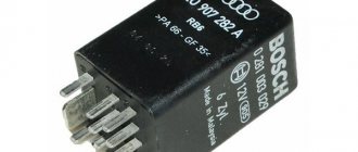
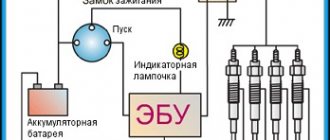
- To carry out a complete diagnosis, electrical diagrams of components and component connections are required. The ignition system can be of two types. In early versions of cars, the traction relay received power from the ignition switch contact group. If it is faulty, no voltage is supplied to the relay. In this case, you should check the contacts using the connection diagram. On machines of the latest versions, a relay located in the mounting block is used to operate the starter. It is necessary to check its serviceability.
- At the next stage, you should ring the wiring going to the starting unit. It consists of thick and thin wire. A thin conductor is needed to control the traction relay, a thick one is needed to start the electric motor. To restore the wiring, you need to strip the wires in a convenient place. If after completing the work, the starter still does not respond. The following problems are possible: broken windings, no contact in the connection of a thin wire, broken commutator lamellas, no grounding on the power unit housing.
- If the starting unit does not spin when the relay is activated, you need to check the power supply at the output of the thick wire; it must be at least 12V. If the contacts are burnt, they need to be cleaned. The condition of the thick conductor should be checked at the positive terminal of the battery.
If the above methods do not resolve the problem, you need to remove the starter and diagnose it (author of the video Made by Hand).
Transformer interturn short circuit
Transformers have a common malfunction - the short circuit of the turns among themselves. It is not always possible to detect this defect with a multimeter. It is necessary to carefully inspect the transformer. The winding wire has varnish insulation; when it breaks down, there is a resistance between the turns of the winding that is not zero. This leads to heating of the winding.
When inspecting the transformer, there should be no burning, charred paper, swelling of the fill, or blackening. If you know the type and brand of the transformer, you can find out what the winding resistance should be. The multimeter is switched to resistance mode. Compare the measured resistance with reference data. If the difference is more than 50%, then the windings are faulty. If the resistance data could not be found in the reference book, then you probably know the number of turns, the type and cross-section of the wire, and you can calculate the resistance using the formulas.
To check the transformer of the power supply with a low voltage output, we connect a voltage of 220 V to the primary winding. If smoke or smell appears, then immediately turn it off, the winding is faulty. If there are no such signs, then we measure the voltage with a tester on the secondary winding. If the voltage is reduced by 20%, there is a risk of failure of the secondary winding.
If there is a second serviceable transformer, then by comparing the resistances the serviceability of the windings is determined. To check in more detail, use an oscilloscope and a generator.
Do-it-yourself diagnostics of the engine starting device
For accurate diagnostics, you need a stand for testing generators and starters, which service stations are equipped with. But you can diagnose the starter yourself.
To carry out diagnostics correctly, you should know the basic rules and sequence of work:
- First of all, the starting device is diagnosed,
- Next, the traction relay is checked,
- then the armature and brush assembly are checked,
- At the final stage, the Bendix is diagnosed.
For a general check of the starter, it must be dismantled and clamped in a vice. The unit must be securely fixed, but not tightly clamped, so as not to cause mechanical damage during testing. Then you need to take a piece of wire and close the contact bolts. A working mechanism will begin to move. In this case, there is a possibility that the solenoid relay is faulty.
You can check the starting unit using the battery by connecting it directly. To figure out how to connect the starter directly to the battery, you need to study the connection diagram. The body of a securely fastened starter must be connected to the negative terminal of the battery, and the positive terminal to the switching contact of the device and the upper terminal of the solenoid relay. If the device is working properly, the engine will turn the gear and the bendix will extend.
To check the retractor, you need to connect the relay and the positive terminal of the battery with one wire, and the body of the device with the negative terminal of the battery with the other. If the relay is working properly, the armature will advance the gear and a characteristic sound resembling a click will be heard.
The next thing to check is the device's armature. To do this, you need to apply 12V voltage directly to the starting unit, bypassing the traction relay. In this way, it is impossible to determine exactly what is faulty: the brushes or the armature windings. The cause of the malfunction can be determined visually by disassembling the unit. You can additionally check with a multimeter.
Bendix is a device responsible for the silent operation of the starting unit. To check, the dismantled bendix must be clamped in a vice. When doing this, use a soft cloth to avoid damaging the device. The Bendix clutch should only turn in one direction. If it rotates in both directions, then the cause of the malfunction is its breakdown. In this case, the part must be replaced.
Photo gallery
1. Checking the starter bendix
2. Checking the armature and brushes
3. Checking the brushes for ground
4. Diagnostics on a special stand
After replacing faulty parts, the starter is assembled. Rotating parts must be centered. The functionality of the device is checked before installation on the engine.
Bendix diagnostics
If the starter turns on but the engine does not turn over, it's time to find out how to check the starter bendix. Bendix is usually not repaired, but replaced, but you need to know the reasons for its failure. There are not many of them:
- the lubricant has dried out or thickened;
- the springs are worn out;
- Defects and abrasions have appeared on the rollers or diametrical wear has occurred.
Checking the Bendix is done without any difficulties. Consider using a soft pad to wrap around the mechanism to prevent damage.
Then place it in a vice, with the device coupling turning one way. If there is rotation in both directions, the cause of the breakdown is a defective coupling.
This part will have to be replaced. By following the exact procedure and instructions, you can easily check the starter and replace defective parts.
Subscribe to our feeds on Facebook, Vkontakte and Instagram: all the most interesting automotive events in one place.
How to repair a VAZ-2107 starter with your own hands
To repair the starting unit yourself, you must:
- remove and disassemble the device;
- check the condition of the windings, bushings and brushes;
- replace damaged elements;
- perform reassembly and check the correctness of the electrical wiring connections.
Dismantling and disassembly
To remove and disassemble the unit you must:
- Disconnect the terminals from the battery, and then remove the battery from the engine compartment.
- Remove the protective shield under the power unit, which limits access to the electric motor.
- Unscrew the nuts holding the wires to the starter housing.
- Using a wrench, unscrew the bolts connecting the electric motor housing to the power unit crankcase.
- Pull the assembly out of the seat.
- Unscrew the solenoid relay nut and remove the assembly from the electric motor housing.
- Unscrew the tightening bolts and carefully remove the covers, and then remove the rotor from the stator.
Replacing bushings
Replacement of starter bushings is carried out when the gap between the shaft and the support is increased. Due to a violation of the relative position of the parts, the rotor touches the stator plates. To eliminate the defect, it is necessary to remove worn parts.
The damaged front support is knocked out of the mounting hole with a handy tool, the rear blind bushing is removed with a puller or drilled out on a machine.
To install new elements (made of bronze or composite material), mandrels made of soft material (for example, wood) are used. During installation, do not warp parts or use excessive force.
Before installation, the composite bushings are kept for 5-10 minutes in a container with motor oil, which saturates the porous surface. Bronze bearings are lubricated when installing the rotor shaft.
Replacing electric brushes
To supply voltage to the rotor windings, a flat commutator and brushes (made of a mixture of graphite and copper powder), pressed by springs, are used. The number of brushes corresponds to the number of poles; the design of the elements includes an elastic stranded wire. During operation, the graphite elements wear out and burn, and at the same time, wear appears on the collector.
Replacement of graphite brushes is carried out according to the following algorithm:
- Remove the back cover of the case.
- Unscrew the screws securing the brushes (there are 4 elements in total).
- Remove worn elements and install new brushes.
- Clean the stator cavity from residual wear products of graphite elements.
- Install the removed parts in their original places.
Repair of starter retractor relay
The electromagnetic retractor relay ensures the movement of the gear on the rotor, which engages with the flywheel ring gear when the electric starter is connected to the vehicle's on-board network. The device is located on the body of the starting unit; the design of the circuit includes an additional power relay (located under the hood).
If the unit breaks down, it is necessary to check the functionality of the control relay. It is recommended to tighten the fastening screw and make sure that there are no oxides on the contact plates and wiring.
To test the relay, you must close the starter directly. If the rotor rotates, the electromagnetic unit must be replaced. Additional diagnostics involves measuring the voltage of the windings with a test device.
Serviceable coils have a resistance of 75 and 55 Ohms (for the holding and retracting windings, respectively). If the value differs from the factory parameters, then the unit must be replaced; it is impossible to repair the relay with your own hands or in a workshop.
The owner can remove the relay on the installed starter. After disconnecting the battery, the surface of the electromagnet is cleaned of dirt, and then you need to disconnect the wires (secured with nuts).
Then the bolts securing the relay to the motor housing are unscrewed. The assembly is disengaged from the rear cover. The new electromagnet is installed and connected in the reverse order.
Starter assembly and installation
The unit is assembled in the reverse order. The design of some units includes retaining rings or cotter pins that must be installed in place. The connected unit must be checked for functionality. The starter assembly procedure is shown in videos filmed by the owners in the process of self-repairing the unit.
Where should repair work begin?
To start repairs and carry out diagnostics without a stand for testing generators, you need to prepare:
- a set of keys;
- screwdrivers;
- special pullers;
- tester;
- control light;
- old rags.
Before checking the starter, it must first be removed and cleaned of dirt. Disassembly requires special tools. To make a thorough diagnosis, the device must be completely disassembled, down to the smallest parts. Then each part needs to be washed and dried.
Machine starter device
Diagnostics without a stand for generators consists of a sequence of actions:
- First of all, you should check that the device is functioning correctly.
- Check the solenoid relay.
- Perform brush and armature diagnostics.
- Call the power grid.
- Carry out a Bendix diagnostic, thanks to which the engine starts silently.
After performing the diagnostics, you should replace or repair the faulty parts.
Photo gallery
The photo shows the stages of repair and troubleshooting of a gearless starter; the design of the components is clearly visible.
Starter parts set Four brush holder design
Armature commutator
Front armature with bendix guides
Shaft corrosion
Rust inside the bendix Example of the location of the bendix at the operating point Bendix is closed with a lid
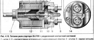
Solenoid relay
Cover with relay and installed bendix
Verification Guide
The device can be checked without removing it from the car. Removal is carried out in case of serious damage. No special knowledge is required for diagnosis. The device is checked in several stages. The most important thing is to check with thick wires; it won’t work on thin ones.
Stages
Checking the starter assembly. To do this, you need to remove the device from the car and clamp it in a vice, securely, but not too tightly, so as not to break it. Then you need to close the contact bolts located on the back side using a metal object or a piece of wire. If the starter is working, it will start spinning. In this case, the cause of the malfunction may be in the traction relay.
Checking the operation of the traction relay. To do this you need to use wires with low resistance. One wire needs to connect the positive terminal on the battery and the relay to ground, and the second wire must connect the negative terminal on the battery and the starter housing. If the relay is working properly, a characteristic click will sound and the armature will push out the gear (video author - altevaa TV)
Checking the anchor. To do this, you need to apply 12 V voltage directly bypassing the traction relay. We check with a test light. The armature is connected to the power supply, and the device body is connected to the light bulb. If the light bulb lights up or sparks, it means that the armature has a breakdown and needs to be replaced.
The tester should measure the resistance between the rotor housing and the windings; it should be several million Ohms. If the insulation resistance is from 0 to 2 ohms, the armature is faulty and requires replacement. Checking the inter-turn short circuit is done using a special stand for testing generators.
Checking the device on the stand
Checking the brushes is done using a 12 V light bulb, which is connected to the brush holder and the body of the device. A glowing light indicates a brush malfunction. In this case, they need to be replaced. The winding is also checked with a light bulb, only the winding and the housing are connected.
Call the electrical network. Using a tester, you can ring an electrical circuit to find breaks. To ring the electrical network, you must turn on the ignition.
Checking the Bendix. To check, you will need a soft gasket to protect the part from damage. The Bendix sprocket must be clamped in a vice and the clutch turned in one direction and the other. If the part is working properly, the coupling will only turn in one direction. If it turns in the other direction, this indicates that it is faulty and needs to be replaced. The teeth may be worn out, then the bendix just needs to be replaced.
Gouges in Bendix teeth
A visual inspection can reveal the following faults:
- winding breaks;
- insulation violation;
- wear of the collector plates;
- surface defects of the commutator and armature in the form of burrs, scratches, grooves, etc.
Small defects can be eliminated by sanding with fine-grained sandpaper. If as a result of these actions the anchor has decreased in diameter, spacers are installed. The same applies to the collector. If the parts are very worn, it is better to replace them. Replacement is required if the interturn insulation is faulty, brushes and bearings are worn out.
By learning to check the device that starts the engine with your own hands, you can save on visiting a service station.
If you don’t know how to check the starter without removing it from the car, diagnostics can be done at service stations that are equipped with a special stand for diagnosing generators.
Sorry, there are no surveys available at this time.
Homemade device for determining turn circuits
Let's make a choke with our own hands to check the interturn short circuit in the motor winding. We will need U-shaped transformer iron. It can be taken, for example, from the old vibration pump “Rucheek”, “Malysh”. We disassemble its lower part and heat it well. There are coils filled with epoxy resin.
We heat the epoxy and knock out the coils with the core. Using sandpaper or a grinder, we cut off the jaws of the core. These coils are wound just on the U-shaped transformer iron.
No need to respect angles. You need to make a place where a small and a large anchor can easily fall.
When processing, it is necessary to take into account that the iron is laminated. You cannot treat it in such a way that the stone lifts it. It is necessary to process in such a direction that the layers lie towards each other so that there are no scuffs. After processing, remove all chamfers and burrs, since you will have to work with enameled wire; it is not advisable to scratch it.
Now we need to make two coils for this core, which we will place on both sides. We measure the thickness and width of the core in the widest places, along the rivets. We take thick cardboard and mark it according to the size of the core. We take into account the size of the groove in the core between the coils. We run the non-sharp edge of the scissors along the bend points to make it easier to bend the cardboard. We cut out the blank for the coil frame. Fold along the fold lines. This creates the frame of the coil.
Now we make four covers for each side of the coils. We get two cardboard frames for the reels.
We calculate the number of turns of the coils using the formula for transformers.
13200: 7.56 = 1746 turns for two coils. This number is optional; a deviation of 10% in both directions will not play any role. Round up, 1800: 2 = 900 turns need to be wound on each coil. We have 0.16 mm wire, it will fit our coils just fine. You can wind it any way you like. 900 turns can be wound manually. If you make a mistake by 20-30 turns, then nothing bad will happen. Better to wind more. Before winding with an awl, we make holes along the edges of the frame for the output of the coil wires.
We put a heat shrink sleeve on the end of the wire. We insert the end of the wire into the hole, bend it, and begin winding the coil.
The filling turned out to be small, so you can wind it with thicker wire. We solder the wiring with a cambric to the other end and insert it into the hole. Do not wind the coil until the test has been carried out.
Both coils are wound. We put them on the core so that the wires go down and are on one side. The coils are wound exactly the same, the direction of the turns is in the same direction, the ends are brought out in the same way. Now you need to connect one end from one coil and one to the other, and apply 220 volts to the remaining two ends. The main thing is not to get confused and connect the correct wires. To understand the connection order, you need to mentally straighten our U-shaped core into one line, so that the turns in the coils are located in the same direction, moving from one coil to the second. We connect the two ends of the coils. We apply voltage to the two ends.
Let's compare a factory choke and a homemade one.
We check the factory choke with a metal plate for vibration in the place of turn short circuits of the motor armature and mark them with a marker. Now we do the same on our homemade throttle. The results were identical. Our new throttle is working fine.
We remove our coils from the core and secure the windings with electrical tape. We also insulate the solder with tape. We put the finished coils on the core, solder 220 V power to the ends of the wires. The inductor is ready for use.
Expert recommendations
If you have no experience in repair work, then you can contact a specialist who will tell you how to check the removed starter from the battery; the video can also help with this. If you carry out a comprehensive diagnosis and repair of the starting unit (replacing bushings, brushes, forks, bendix if necessary, cleaning internal surfaces), then it will last without repair for 3-4 years.
To extend the service life of the starter, you must adhere to the following rules:
- do not force the starter to operate continuously for 15 seconds,
- if extraneous noise is heard or the device periodically fails, you must immediately look for the cause of the malfunction and eliminate it,
- monitor the condition of the traction relay contacts; sparking and overheating of the contacts can destroy the part.
A working starter will ensure a comfortable trip and will not fail at the right time. It is better to correct minor problems in a timely manner than to make major repairs. The given tips on how to check the operation of a starter from a battery, the videos posted in the article will help to carry out a set of routine maintenance to restore the starter’s functionality.
What to do if the starter does not turn?
It cannot be said that the VAZ 2107 starter has some unique set of faults. As a rule, these problems occur when operating any VAZ car model.
What actions need to be taken if the gear starter turns poorly or does not turn at all after turning the key in the ignition switch:
- The first thing you need to do is look at the warning lights; their dim light or periodic fading indicates that the battery is low;
- Check the pole terminals and tips of the battery wires, if they are oxidized, you need to clean them and lubricate them with Vaseline, tighten them tightly;
- Check the relay winding for a short circuit; if it occurs, the relay will need to be replaced;
- Check the relay connections for breaks in the power supply.
Sources
- https://dorpex.ru/avtomobilnaya-elektronika/potrebiteli-elektroenergii/prostyie-sposobyi-kak-mozhno-samostoyatelno-proverit-starter-na-rabotosposobnost
- https://osensorax.ru/remont/kak-proverit-starter-multimetrom
- https://smotri-dtp.ru/pomoshh-avtomobilistu/kak-proverit-starter-na-rabotosposobnost.html
- https://lada-xray2.ru/sovet/proveryaem-starter-ne-snimaya-s-avto
- https://worldofgold.ru/kak-proverit-starter-cherez-akkumulyator-vaz-2107/
- https://labavto.com/kak-proverit-starter/
- https://gil-service.ru/ts/kak-proverit-starter-ot-akkumulyatora.html
- https://kalina-2.ru/remont-vaz/proverka-startera-vaz-2107-ot-akkumuljatora
Working with an ohmmeter
Sincere could occur due to the loss of electrical contact in one of the lamellas. To measure resistance, it is recommended to place probes on the side of the current collectors. While rotating the motor shaft, observe the dial readings. The screen should show zero values. If the numbers slip by even a few ohms, then this indicates carbon deposits. When an infinite value appears, an open circuit is judged.
Regardless of the results, you should next check the resistance between each adjacent lamellas. It should be the same for each measurement. In case of deviations, you need to inspect all the connections of the coils and the contact surface of the brushes. The brushes themselves should wear evenly. If chipped or cracked, they must be replaced.
The coils are connected to the core by wiring that may have come loose. Solder often does not withstand shock from drops. In a starter, the current through the contacts can reach 50A, which leads to burnout of poor-quality connections. External inspection determines the location of damage. If no malfunction is found, then measure the resistance between the lamella and the coil itself.