For many car owners, the relay turns out to be a very incomprehensible thing. Its malfunction may affect the failure of various equipment, so you need to know how to check the functionality of the relay.
To understand the operating principle of this device, it is worth reading the very detailed article How relays work in a car. In short: there is a small electromagnet installed inside the relay housing. When voltage is applied to its contacts, it attracts the jumper, and it closes the contacts of the power line - the equipment turns on. Based on this, there are certain relay malfunctions that can lead to its failure.
When troubleshooting any equipment connected via a relay, you need to check whether it is working. In modern cars, relays are installed in mounting blocks, so it will be based on this. If you have a “free-standing” relay, the testing principles are the same.
Checking the presence of power at the control contacts
When certain conditions occur that are necessary to turn on the equipment powered through the relay (for example, turning on the headlights from the interior), the relay should click. If there is a click, then we immediately move on to the next section of the article about power contacts. If there is no click, you need to check the presence of voltage at the control contacts. You can determine the presence of voltage with a regular test light or a multimeter. Moreover, the multimeter is able to show low voltage, which the light bulb “will not notice.”
To measure the voltage at the relay contact, in some cases it is enough to slightly pull it out of the mounting block socket and touch the probe of a test lamp or multimeter to one of the control contacts. The second dipstick, accordingly, needs to be leaned against the metal of the body. However, it is safer and easier to pull out the relay completely and insert the probe into the desired socket of the block.
If there is no voltage at any control contact, it means that the relay will not turn on and most likely it is not to blame for the equipment failure. You need to look for the reason why current does not flow to the relay.
In order for the magnet located inside the relay to work, in addition to the “plus”, there must also be a “ground”, that is, a connection to the body. You can check its presence using the same “control”. Place one lamp probe on the positive terminal of the battery, and the second in the “mass” socket of the mounting block. Just do not connect these places with a regular wire - this will lead to a short circuit! A light bulb or multimeter will eliminate this danger and show whether there is a mass connection in the corresponding socket.
We check the presence of voltage at the power contacts of the relay
If the relay clicks, it means that the control electrical circuit is working, the magnet is activated and the jumper moves. In this case, you need to check the presence of voltage at the power contacts of the relay. There is always voltage on one contact, and on the second it should appear when the relay is turned on. With the equipment connected through the relay being tested turned off, locate the power contact that is energized. To do this, insert the test lamp or multimeter probe into the corresponding socket of the mounting block, and the other end into the car body.
If there is no voltage at any power contact, it means that the power line is faulty and the relay has nothing to do with it either. The reasons for power line failure can be different, but first you should check the fuse. If there is voltage at one of the power contacts of the relay, then when the relay is turned on (the relay clicked, there is voltage at the control contacts), there should be voltage at the second power contact.
If the relay is turned on, and there is voltage on only one power contact, it means that current does not pass through the relay contact group. This usually happens due to burnt contacts of the jumper that closes the power line. It is easier to replace such a relay with a new one, since disassembling this structure and trying to clean the jumper is a rather difficult and unreliable task. Moreover, the cost of most relays is low.
A relay is a device designed to control high power signals with low power signals. Its main task is to separate and protect the low voltage circuit with an electromagnetic coil from the high voltage circuit. There are several ways to verify that the relay is working; the most convenient, fastest and most reliable is to use a multimeter.
Types and characteristics
Depending on the element base used, relay regulators are divided into the following types:
- Microcontroller or microprocessor based. Their peculiarity lies in the inclusion of a working algorithm in the built-in chip. Used in expensive cars, such as BMW or Audi.
- Relays are based on switching relay contacts to cut off and stabilize the performance of the electrical network.
- Integrated relays are widely used in the automotive industry. The operating principle is based on solid-state switching parts or integrated semiconductors.
- Hybrid transistor-relay devices and simply transistor ones are based on semiconductor elements. They were actively used in industry until the early 90s.
Based on their design, they are divided into the following types:
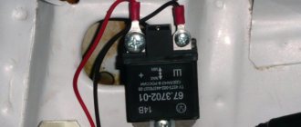
- External relays are separate devices that are installed on body structures.
- Built-in switching parts are an integral part of generators.
- Combined or hybrid. Their peculiarity lies in their combination with the brush assembly of an electric generator.
An electric relay can be two-, three- or multi-level, divided into “+” and “-”.
It's time to stop
In fact, expressing your displeasure by beeping is completely inappropriate. The taxi driver will continue to behave in the same way on the road, regardless of your signal. In cities, it is illegal to use your horn in a residential area unless there is a traffic situation where you really need to do so, otherwise you will face a fine. In general, beeps are not intended to give your teenage son the opportunity to signal to his girlfriend that he has been waiting for her on a date. A short horn will help attract the attention of a pedestrian who steps out onto the roadway without looking around, or of some mother who is driving her children to the section, chatting on the phone and looking in the rearview mirror at her whining offspring.
Symptoms of a problem
Before checking the relay with a multimeter, you should familiarize yourself with the main signs that the part has failed.
- There are cases when, as a result of the failure of the voltage regulator, the battery boils.
- When the ignition is turned on, the control light on the dashboard does not light up (however, this can be a symptom of other types of malfunctions, for example, a contact has fallen out or burned out).
- The dynamic characteristics of a household appliance or car are reduced, especially when the engine reaches high speeds.
- After starting, the battery indicator does not go out on the dashboard, which indicates a battery problem.
- The indicators on the dashboard simply turn off if the engine speed during operation exceeds 2000 rpm.
- The brightness of the headlights depends on the engine speed. It is quite simple to verify this - you need to stand in front of the wall in the dark and turn on the headlights. The brightness of the glow will change depending on how hard you press the gas.
- The battery is regularly discharged.
These signs may indicate other malfunctions, but first of all it is recommended to check the relay regulator.
How does a wiring diagram benefit you?
Although domestic cars will be simpler than foreign cars, they all consist of a huge variety of different components, power and fuel units and, of course, sophisticated electrical equipment. The dear VAZ-2112 could not do without a modern electrical part. The right turn has stopped working, there is no low beam headlights, the horn is silent and does not buzz, a light bulb in the trunk has burned out or the radiator fan has stopped turning on. What to do, where to run and who to ask?
Every car owner should at least get to know the electrical part of his car in general terms. Where to begin? Rummage through the glove compartment, and if your wife has not yet put things in order, you can find there the “Operating Manual for the VAZ-2112”
Among other things, this necessary book contains a lot of important information on the electrical part. Having at least a little insight, in the future you will not only save on repairs at a service station, but also avoid ordering a tow truck when suddenly your “beloved” becomes rooted to the spot in the middle of a field
Reasons for failure of the relay regulator
In order to minimize the likelihood of repeated breakdowns in the future, you should familiarize yourself with the main reasons for device failure.
- Short circuit in any part of the electrical circuit, including interturn short circuit of the excitation winding.
- The regulator may also fail if the diodes break down or the rectifier bridge breaks down.
- Incorrect connection or reverse direction to the battery terminals.
- Penetration of moisture or large amounts of dust into the generator and/or the regulator itself (such cases are common during heavy rainfall or when washing the car).
- Mechanical damage to the working unit.
- Natural wear and tear, end of service life.
- Initially, the quality of the purchased product is questionable.
Preparing to test the relay for functionality
Checking the relay will not take much time if all the preparatory work is done correctly.
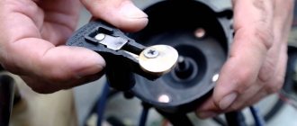
Before you begin diagnosing the device, you need to determine the purpose of the pins of the part being tested. To do this, use the documentation supplied with the device; it contains all the diagrams and operating features, and the characteristics of the device.
There are common cases when the operating diagram is depicted on the relay body itself. Contacts are represented by dots; they are connected by an inductor, the switching elements are straight lines with a dotted line. The power supply pins are shown schematically as a rectangle.
If the relay is built into the circuit, you need to visually inspect the state of the bus and power traces on the board itself. To check the relay with a tester, you can use both digital and analog instruments. No preliminary preparation or setup of testers is required.
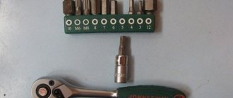
In addition to the tester, you need to prepare a regulated power supply. For the results to be reliable, the relay must be removed from the circuit.
The functionality test is carried out in several stages:
- winding;
- normally closed position;
- normally open state.
Then you can proceed directly to diagnosing the relay.
Diagnostics of windings and contact groups
The winding is an inductance coil on which wire is wound in a spiral. It is characterized by a certain resistance, which is calculated according to Ohm's law. The resistance value should range from 10 to 100 Ohms.
Diagnostics of the winding allows you to find out whether its integrity is compromised. Functionality testing is carried out in several stages:
- The multimeter is turned on in resistance testing mode. On the instrument panel this mode is indicated by the symbol – Ω, the range is set within 2 kOhm.
- One measuring wire is connected to the socket, and the second to the COM.
- The wire probes touch the relay terminals.
The resistance of the inductor can be determined by the deflection of the arrow.
Checking contact groups is carried out in two stages. First, the resistance must be measured offline, and then when voltage is applied to the coil. When checking, you will need a power source, you need to take care of this in advance.
How does it work
It helps to think of the relay as a regular switch, like the one you use at home to turn the lights in a room on and off.
They work in a similar way, but instead of reaching down to directly turn on the internal switch, you activate a control circuit that connects to a coil inside - this happens to the fuel pump relay when you turn the ignition on. for example, to start the engine.
The coil creates an electromagnetic field that covers a pair of metal contacts inside that connect to a controlled circuit that activates a load—such as an electric fuel pump.
Why duplicate a simple switch function by having an extra switch inside the box?
In fact, this has proven to be a convenient setting in electrical circuits. Not only are you using a small, safer current circuit - the control circuit - to turn on and off a higher current circuit - the control circuit - but it can be strategically placed to reduce the amount - and cost - of thicker test wire needed to high current circuits.
Abnormal voltage readings on the multimeter
If the multimeter shows low voltage in the battery, the battery will simply stop accepting charge. As a result, the car may not start, the indicators on the dashboard may stop working, and troubles may arise while driving.
If the voltage is increased, there is a possibility that the level of electrolyte in the battery bank has decreased, or it has simply boiled away. Another characteristic feature may be the formation of a white coating on the walls of the body. When recharging, the battery may begin to behave unpredictably.
An electromagnetic relay is an electromechanical device that, when exposed to current, closes or opens mechanical contacts. And they, in turn, close an electrical circuit, usually with large currents compared to the control signal.
Features of the mirror heater device
To repair the heating element, you can use one of the commercially available special kits that contain silver. Any modern car is equipped with all kinds of heating systems. Standard devices that no car can do without include a cabin heater and rear window heating.
Break. It also often happens that conductive threads burn out or break, as a result of which the current does not flow beyond the break point.
Lada (“Lada”) is a brand of cars produced by AvtoVAZ JSC. Previously, it was used only for export cars, and for the domestic market, cars were produced under the Zhiguli brand. In 2004, the management of AvtoVAZ announced the transition to the Latin alphabet for the official spelling of the names of all cars produced by the plant: Lada - instead of "VAZ" and "Lada".
Instrument cluster, pin “21”. Electrical package controller, contact “9” of block X2. Electromechanical power steering control unit, contact “1” of block X2. Reversing light switch. Reversing lamps.
Measure the voltage on all strips one by one with a voltmeter, connecting one terminal of the body voltage and the other in series to the conductive strips.
Go see a good electrician and let him try soldering, just be careful, don’t heat the glass too much... If it works, the contact should be reliably held, because... can get very hot, after all 20 A before
costs.
Before replacing a blown fuse, find out the cause of its blown and eliminate it. When troubleshooting, it is recommended to look at the circuits that are protected by this fuse.
If you don't have a multimeter, use an alternative method. If the housing is transparent, check the integrity of the filament with light (its damage is easy to see). For fuses with an opaque casing, this option will not work.
Operating principle
Essentially, a relay is an electromagnet. When control voltage is applied to the coil, the rod attracts the armature, thus switching the circuit.
There are three types of relays:
- with normally closed contacts;
- with normally open;
- throwing over.
When a control signal is applied to a device with normally closed connectors, they open; if there is no signal, they close. For relays with open connectors, the opposite is true. There is voltage on the winding, the terminals close, but when there is no voltage, it opens. In flip-over models there are two sets of connectors, one normally closed and the other normally open. They have a common terminal. When current is applied to the winding, the contacts switch from one position to another.
Switching device design
An electrical relay is a device designed to be used as a switch. It can connect or disconnect an electrical circuit depending on the control signal coming to it. The line that is connected to the element is called controlled, and the one through which the command is sent to it is called control.
Relays are used to automate various operations. They successfully cope with managing various kinds of signals and protecting electrical equipment. They are used in security and heating systems, sound engineering, that is, wherever automatic switching of operating modes is necessary when any parameters change.
When searching and eliminating various faults in equipment, one of the repair stages is to test the switching element. This is done using a quantity meter. But before you test the relay for functionality with a multimeter, you should know how it works and understand the principle of its operation.
Principle of operation
A relay is an electromagnet consisting of a contact group, an armature and an inductor. All parts are installed on the base and placed in a closed housing. The elements are mounted as follows: an anchor (yoke) is placed on top of the core of the magnetic system. It is held in its initial position by a spring and is a movable L-shaped plate.
A group of plates with contacts is attached to the lower arm of the transmission, and the same number of contact bases is installed opposite them. Each lamella contact extends outward from the housing, forming the terminals of the device.
The principle of operation of an electronic device is the ability of an electromagnetic field to influence conductive objects. When voltage is applied to the terminals of the winding, current begins to flow through it. When its value reaches a certain value, two forces (electromotive and magnetic) arise in the winding, forcing the armature to press against the surface of the coil, overcoming the force of the spring.
At the same time, the arm with the attached contact plates also moves, arching them in such a way that they break contact with the connected group. As a result, electrical contact occurs. If connected to the terminals of these plates, the line is closed.
Depending on the design, the initial position can be either closed or open, so in the second type of relay, after applying voltage, the line will open. As soon as the signal of the required amplitude is removed from the terminals of the relay winding, the contacts of the device will return to their original state.
Types and characteristics
Electrical relay elements differ in the number of pins and shape, but their essence remains the same - connecting or disconnecting the load from the signal line. According to the type of physical processes that lead to recommutation, relays are divided into the following types:
- neutral - do not depend on the polarity of the signal supplied to the control terminals;
- polarized - in them the position of the contacts depends on the direction of the current;
- magnetoelectric - react only to direct current;
- ferrodynamic - their design uses ferromagnetic cores that enhance the magnetic flux;
- induction - based on the connection between a changing magnetic flux and an induced current in a conductor;
- thermal - react to heat that appears when current passes through the plates and changes their shape;
- electronic - they use the property of a pn junction to conduct current in only one direction (diode).
Devices are also divided according to the type of contacts, which can be of three types: normally closed, normally open and changeover. Like any electromechanical device, a relay is characterized by its technical parameters that determine the operation and purpose of the device. Of course, it will be impossible to check all the parameters of the relay with a multimeter, but with its help you can accurately determine the functionality of the switch. The main characteristics of the device include:
- winding voltage is the value of the signal amplitude at which the relay switches from one stable state of contact connection to another;
- switching current denotes the highest value of current that the relay can pass through without changing its parameters;
- the rated voltage is divided into values corresponding to alternating and constant signal levels, indicating the maximum potential difference, the appearance of which is permissible at the terminals connected to the load;
- operating frequency is the number of switchings that a device can perform per unit of time;
- wear resistance is determined by the mechanical reliability of contact groups, measured in cycles;
- The response time is characterized by the interval during which the position of the contact groups changes after the arrival of the control signal.
Functionality check
On the body of each relay there is a diagram with contact numbers and control voltage rating. A rectangle with pins 85 and 86 means a coil. Therefore, when measuring winding parameters, you need to connect to them. Other pins numbered 30, 87 and 87a (88) are the switching key for the external circuit.
It is convenient to use a digital multimeter as a tester for regulator relays and any other electromagnetic relay. This is because it can measure current, voltage and resistance.
Since the performance of the device depends primarily on the health of the winding, the test begins with measuring the coil resistance. Its values range from several tens of ohms to several hundred ohms.
To do this, switch the multimeter to resistance measurement mode. We connect measuring probes to pins 85, 86 and take readings. If the resistance is within normal limits, then you need to check the condition of the controlled outputs. In a relay with normally closed contacts 30 and 87, when measuring the resistance between them, the multimeter should show 0 Ohm. With normally open pins 30 and 87 the resistance between them should be infinity. When the control voltage is applied to the coil terminals 85 and 86, everything should change exactly the opposite.
Testing internal elements
Always remember that before testing, the relay must be disconnected from the power source! Even capacitors that are disconnected from the network store an accumulated electrical charge.
Take a multimeter and determine the resistance:
if the contact and pole are normally closed, the resistance will be zero;
if the pole and normally open contact - the resistance is greater than 0.
To test the relay acoustically, you need to connect two conductors to contacts 85 and 86. Connect the other ends of the conductors to the battery. You will hear the operating relay immediately - when the conductor and battery come into contact, clicks will appear.
There are clicks, but do the moving and fixed contacts work? Let's find out:
- Take a multimeter and attach its probes to the contacts. If everything is normal, you will hear a whistle.
- If you don't have a multimeter, then you can use a test light. In this case, an additional conductor will be needed. Connect it to the “+” contact and place it on the coil. Connect the second conductor to another contact. We connect the light bulb to “–”. When the relay is turned on, the light should light up.
When any electrical equipment in a car stops working, the first thing to check is the fuse responsible for the problematic element. If the fuse is intact, then the problem may lie in the relay.
Relays are found in many electrical circuits of a car: fuel pump, power windows, heated windows, heated seats and many others. That is why it is important to be able to independently test the relay for functionality using a conventional multimeter.
Application in car
Most often motorists have to deal with switching devices. We are talking about the generator (starter) regulator relay. They remember it when the engine stops starting and it turns out that the battery is discharged. One of the reasons for this is a malfunction of the regulator.
On older cars, to maintain a constant voltage, a regulator was used, consisting of three devices - a voltage stabilizer, a current limiter and a reverse current relay. The regulator prevents the battery from overcharging, which prolongs its service life. It can be built into the starter brush block or performed as a separate module. Its failure may or may not overcharge the battery. In the first case, streaks will be visible on the case, the electrolyte will begin to boil away, which will lead to a voltage drop below 12 volts. In the second, the values will initially be lower than acceptable. As a result, the engine will not start.
Symptoms of problems
How can you even determine that the horn is not working or has some kind of malfunction? It's actually extremely simple.
There are 2 main signs of problems with a car horn:
- The signal doesn't work at all. When you press the button, the driver, like other road users, hear absolutely nothing. This is a clear indication that the system has failed;
- The signal appears periodically. There is also a slightly different situation when the horn does not go off with every press. That is, they pressed it once, everything works, but when you try to honk again, the horn goes silent, there is no reaction to the press. Then the situation repeats itself.
There is nothing complicated or unusual in determining the nature of the malfunctions. But now we need to understand why this happens and where to look for the reasons.
Checking the starter regulator
To check the starter regulator relay without removing it from the car, you can use a multimeter and test all the wires that go to it. To do this, they are first disconnected from the regulator. The multimeter is switched to resistance measurement mode, the disconnected wires are checked.
If everything is normal, then the conductors are returned to their place. The voltage at the battery terminals is measured with the engine off. The multimeter is switched to DC voltage measurement mode in the range from 0 to 20 Volts. The probes attach to the battery terminals. The device should show 12.2-12.7 V. If 12 volts or lower, then it needs to be recharged.
Then the engine must be started and checked again with the same measurements. If the voltage is in the range of 13.2-14 V, then this is normal. We add engine speed to 2000 per minute and measure again. Normally, the multimeter should show between 13.6-14.2 V. We also add revolutions to 3500 per minute.
We take readings. They should not exceed 14.5 Volts. If the value does not change and remains 12.7 Volts, as when the engine is turned off, or even decreases, then the regulator relay is faulty. Therefore it needs to be replaced. If 14.5 Volts are exceeded, the regulator must also be changed.
Sometimes the question arises of how to test a relay with a multimeter if there is no access to the regulator. Then you need to remove it, and to check it you must have, in addition to the tester, a charger with a voltage regulator and a light bulb. The following scheme is assembled from them. The charger is connected to the input terminals of the regulator, and the light bulb is connected to the output (thick) terminals. A multimeter monitors the voltage at the regulator input. By charging we change the voltage from 12 to 15 volts. The light should go out at 14.5 volts. If this does not happen, the regulator is faulty and must be replaced.
What to do if the multimeter does not have a dialing mode
Some budget electronic testers do not have a separate dialing mode with a sound alert, but they can also check the integrity of the circuit , but this is not so convenient.
For example, the fairly popular dt 830b does not have a buzzer, but there is a diode test mode, you can use it by observing the change in readings on the screen. The probes are connected in the same way as described above into the COM and V Ω mA .
If the readings on the screen during measurements differ from one, then there is an electrical connection in the area being tested. You can check the functionality of this method by connecting the probes; if everything is in order, then zeros should appear on the screen.
In multimeter models, where there are no additional functions at all, in particular in analog instruments, you can ring by switching the regulator to the resistance measurement mode - ohmmeter.
In this case, it is necessary to select the lowest available threshold - for example, 50 Ohms or 200 Ohms. Then measure according to the usual scheme described above and watch the changes in the readings on the screen - if there are changes, the circuit is intact. For home, everyday conditions, this is quite enough to find which wire is broken, determine the burnt track on the board, and much more.
That's all for me; in my opinion, this information is quite enough for anyone to learn how to dial with a multimeter, even without ever doing it before. If you still have questions or have healthy criticism or additions, be sure to write in the comments to the article, in addition, subscribe to our VKONTAKTE group - stay tuned for new materials.
In the following articles we will talk about other useful functions and ways to use a digital multimeter in everyday life, determine the phase and zero in an outlet, measure the voltage in the network and much more, stay tuned .
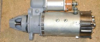
Checking the solenoid relay
When the battery is charged, but the engine does not start, you need to check the starter.
If the generator spins but the engine does not, then in such cases it is necessary to check the solenoid relay of the electric motor and the bendix. To do this, you need to remove the starter. After this, all contacts are cleaned, and the resistance of the relay winding is measured with a multimeter. If the value is infinity, then the winding has burned out. In this case, it is necessary to rewind the coil or replace it. The device shows several tens of ohms, which means the winding is intact.
Then its performance is checked. The positive terminal of the battery is connected to the corresponding relay terminal using the cigarette lighter. And the minus is connected to the starter housing. A click should be heard, then the device is working properly, otherwise it needs to be disassembled and the mechanical part checked.
Video
You can watch the relay testing process in detail in the video.
But you can learn about how to check the wiring in a car for a short circuit or break in other useful articles on our website.
A relay is a device designed to control high power signals with low power signals. Its main task is to separate and protect the low voltage circuit with an electromagnetic coil from the high voltage circuit. There are several ways to verify that the relay is working; the most convenient, fastest and most reliable is to use a multimeter.