General check of the distributor
Unstable operation of the power plant at idle, jerking when driving, vibrations and many similar problems can occur if the distributor is faulty. We will learn from the article how to check the distributor for operability, diagnose the coil and other elements of the ignition system. Let's watch a video review that shows everything in detail.
CHECKING THE IGNITION DISTRIBUTOR. Repair and diagnostics of the electrical equipment system.
How to check the ignition distributor
The main reason for checking the ignition distributor, the engine electrical system, is to check for damage that is not subject to normal repair. Typically, the ignition distributor is checked on a test bench. Before installing the distributor on the test stand, make sure that the condition of the breaker contacts is normal. The lever with a moving contact should not jam on the axis. Check the wear of the textolite block; if the spring of the lever is weakened, or the lever itself is stuck on the axis, the contact group must be replaced.
Contacts that are dirty, burnt or have signs of erosion will need to be treated. For processing, use a velvet file; the use of abrasive materials or sandpaper is prohibited. After cleaning, clean the contacts well.
Wipe the ignition distributor cover from dust and oil residues
When installing the ignition distributor on a control test bench to check the ignition devices, connect it to an electric motor that can adjust the rotation speed.
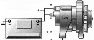
The control test bench must be able to connect the distributor with the ignition coil and battery, similar to the ignition system diagram.
Connect the terminals of the distributor cover to spark gaps, the interelectrode gap of which is adjustable.
Set the interelectrode gap of the spark gaps to 5 mm, turn on the electric motor, set the rotation speed to 2000 rpm. Then increase the interelectrode gap to 10mm, and check for internal discharges in the distributor. The manifestation of internal discharges can be determined by a characteristic sound, or by an interruption and weakening of sparking at the stand's spark gap.
A serviceable distributor should not make noise at any roller rotation speed
To determine the characteristics of the centrifugal ignition timing regulator, set the interelectrode gap of the bench spark gap to 7 mm. At the stand, turn on the electric motor, the speed should be 150 - 200 rpm.
Mark the value in degrees on the graduated disk of the stand, gradually increase the rotation speed by 200 - 300 revolutions, use the disk of the stand to determine the number of degrees of ignition timing, it should correspond to that shown in the image.
- A – ignition distributor P125.
- B – ignition distributor 30.3706.
- Where is the vertical line? A corresponds to the ignition timing in degrees.
- And the horizontal straight line n is the rotation frequency of the ignition distributor shaft in minutes.
If the characteristic shown in the figure differs from the test indicators, it can be corrected and brought back to normal by bending the springs of the centrifugal regulator weights.
If you need to bring the indicator up to 1100 rpm, bend the thin spring strut, and if above 1100 rpm. min. then bend the thick spring strut. To increase the angle, reduce the spring tension; to decrease it, increase it.
To obtain the performance characteristics of the vacuum ignition timing regulator, set the rotation speed for the roller to 1000 rpm. On a graduated disk, determine the value in degrees at which one of the four sparks occurs and mark it. Next, slowly, as they say smoothly, increase the vacuum and record the number of degrees every 20 mm of mercury, record the number of degrees of ignition timing. Compare the obtained indicators with the values shown in the images.
Where the vertical straight line A is the ignition timing in degrees. And the horizontal straight line P is the vacuum in millimeters of mercury.
Between the various terminals and ground, check the insulation resistance using a megger.
To measure the resistance between ground and the low-voltage terminal of the breaker, it must be done with the breaker contacts open. At 25-30 degrees Celsius, the insulation resistance should be at least 10 MΩ (megohm).
If you measure the capacitance of a capacitor in the frequency range 50 - 1000 Hz, the capacitance should correspond to 0.20 -0.25 µF (microfarads)
Methods for checking the ignition coil
Checking the ignition coil using the “old-fashioned” method can damage the electrics of a modern car
To properly check this car part yourself, it is recommended to perform certain steps step by step. First of all, after removing the coil, you need to visually inspect it and make sure that there are no external signs of a short circuit: black dots indicating burnout, cracks, or other signs of breakdown.
In our country, for a long time, there were two equally popular ways to check the ignition coil for functionality: by checking the spark between the car body and the spark plug, or by measuring the resistance of the windings with a multimeter (tester). The use of the first method can be fatal not only for the coil, but also for the electronics of most modern cars, so its use is categorically not recommended by manufacturers. It is safer to check this component of the car with a measuring device.
Setting the ignition using a strobe light
You can adjust the ignition timing using a strobe, but the “manual” method has exactly the same effect. The only negative is that it takes longer to set up, but you can find the most effective ignition timing when the engine produces maximum power.
Installing the ignition on a VAZ engine photo
“Strobe” (as it is popularly called) is a device that pulses the crankshaft position mark at the moment of spark formation. To put it simply, while the engine is running, you can direct the beam of this device to a mark that serves to regulate the ignition timing. We see this mark as stationary, although it is located on a pulley or rotating flywheel (depending on the car model).
Checking the performance of correction systems with a strobe:
- We warm up the engine and remove the “choke”; the idle speed should be adjusted to normal (or slightly lower). We remove the vacuum tube that goes from the carburetor to the “vacuum manifold” of the distributor. Next, in this mode, we adjust and check the setting of the initial ignition timing. In the “classic”, this angle should be from 2 to 7 degrees, it depends on the engine displacement. For example, VAZ 2108-2110 - 1100 cm - 6 g, 1300 cm - 1 g, 1500 cm - 4 g. It is better to find out more in the car description).
- As the engine speed increases, to approximately 2000, the advance angle should increase by 5-7 degrees. If there are no changes, this means that the centrifugal regulator is not working. The main cause of failure may be jamming of the centrifugal mechanism, most often this occurs due to oxidation. For repairs, you need to disassemble, clean and lubricate. In addition, the springs of the mechanism often break.
- To check the operation of the vacuum ignition timing regulator, you need to make more effort, since its performance is related to the operation of the carburetor. The most important condition for good operation of the vacuum corrector is that while the engine is running at idle speed, there should be no vacuum in the tube that goes from the carburetor to the “vacuum manifold”. It should only appear when the engine speed increases. The moment a vacuum appears in the tube can be checked by carefully placing the tip of your tongue on it. You need to apply it to the end of the tube that we removed initially. If the carburetor does not provide timely vacuum in the tube, then the vacuum corrector will not work normally, even if the distributor mechanism is fully operational.
Procedure for adjusting the gap
How to test a resistor for functionality with a multimeter
Remove the distributor cap and the slider and, slowly turning the engine crankshaft with the starting handle, set cam 4 to the position where the gap between the breaker contacts is greatest, i.e., when the breaker lever pad is installed on the top of the cam face. After this, use a flat feeler gauge to check the gap between the contacts. If the gap does not correspond to the value indicated above, it is necessary to loosen the locking screw and, by turning the eccentric 23, set the required gap; then tighten the screw and check the gap again. Then you need to put the cover in place and secure it with latches 10. After adjusting the gap between the breaker contacts, the correct setting of the ignition timing is disrupted. Therefore, the ignition installation must be checked and, if necessary, clarified.
Checking the ignition coil with a multimeter
Diagnostics of the electronic engine control system and the electrical circuit of the distributor
The ignition coil is located in the distributor, and to check the voltage it is necessary to bend the latched clamp and remove the wires that go to it from the distributor. Next, you need to take a multimeter and set the parameters on it for measuring voltage. After this, one of the multimeter wires is applied to the terminal of the ignition coil, and the second to the car body (that is, to ground).
The result of such a measurement, with a working ignition coil, should be 12 Volts, displayed on the multimeter. If there are problems with the electronic engine management system or the electrical circuit of the distributor, the multimeter will show 0 Volts.
Checking the secondary winding for open circuit
To carry out such a diagnostic procedure, you need to set the multimeter to the mode for measuring electrical resistance (Ohms). Next, we connect one of the wires of the diagnostic device to the positive or negative terminal of the ignition coil, and the second to the central terminal.
If your measurement results in a value of about 6-8 kOhm, this is considered normal for most coils. Some can produce values up to 15 kOhm, which is also considered acceptable, but it is better to clarify this parameter in the technical documentation of the car. In the case where the deviations in the measured results are serious, in relation to the figures indicated in the technical documentation, we can talk about a break in the secondary winding.
Checking the primary winding for open circuit
The procedure for diagnosing the primary winding of the ignition coil is practically no different from checking the secondary winding. Again, take the multimeter, which is set to measure electrical resistance, and connect its wires to the positive and negative terminals of the ignition coil, that is, to the external contacts (in most cases).
If, as a result of the measurement, the multimeter shows values of about 0.5-2 Ohms, then there are no problems with the primary winding and it is operating normally. When the resistance differs from these values, the fact of a break in the primary winding is stated.
Using a Multimeter When Testing a Coil
How to check the spark on a spark plug
In order to independently get a complete picture of the serviceability of an element of the ignition system, you need to figure out how to check the ignition coil with a multimeter. This procedure should not cause any particular difficulties.
First, the primary winding is checked, to the positive and negative contacts of which the device is connected in resistance measurement mode. Standard factory readings from different manufacturers may vary slightly, but average resistance values should be in the range of 0.4 to 2.0 ohms. If the device shows zero resistance, it means there is a short circuit in the coil, if infinity, you need to look for an open circuit.
Checking the ignition coil using a tester
To check the secondary winding, a multimeter is connected to the positive terminal of the coil and the terminal from the high voltage wire. The resistance value of this winding for coils with a plate core is 6-8 kOhm, for other types the parameter can exceed 15 kOhm.
It is possible to draw a conclusion about whether the obtained indicators are within the limits established for a particular model only by having an idea of its other technical characteristics: the duration and energy of the spark discharge, the spark discharge current and the inductance value of the primary winding.
Any malfunction of the ignition coil has a bad effect on the efficiency of the car engine, and this can lead to a decrease in its durability. That is why its timely diagnosis and repair (or replacement), if necessary, is necessary.
Causes of coil failure
Partial damage to the ignition coil leads to unstable engine operation, and its complete breakdown makes it impossible to start the engine. That is why, when the engine stalls, loses power, or other signs of unclear operation, one of the first actions should be to check the ignition coil. This element fails quite rarely, and the malfunction, as a rule, is as follows:
- Insulation damage due to extreme heat, vibration or high voltage, which in turn leads to a short circuit in the coil windings;
- Overload caused by faulty high-voltage wires or spark plugs can cause the winding in the coil to break.
Distributor repair
Repairing a distributor is a rather complicated procedure, requiring the repairman to know the structure of the unit and the electronics in general. The complexity of the distributor design, the difficult connection diagram and the lack of electrician training among motorists reduce the possibility of its own repair to almost zero. It is based on this that garage technicians often prefer to completely replace a faulty distributor.
Often this approach is completely justified, as it significantly saves motorists’ time. However, when deciding to replace the distributor, you need:
- firstly, try to diagnose the exact malfunction of the device (for example, incorrect operation of high-voltage wires does not require a complete replacement of the distributor, because it is much easier and cheaper to simply change the wiring);
- secondly, consult with a specialist in the field of repairing ignition systems and make sure that it will be cheaper to replace the distributor rather than have it repaired by an electrician.
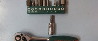
Let's say the need to install a new distributor is confirmed. In such a situation, it is quite advisable to save some money and carry out the replacement yourself. To organize the repair you will need:
- set of wrenches;
- spark plug key;
- screwdriver;
- rags;
- new distributor.
The repair procedure is as follows:
First of all, you need to unscrew the spark plug of the first cylinder and determine where the distributor is located specifically on your model; Next, we proceed to align the motor shafts in the desired position. To do this: jack up the front wheel on the right; close the spark plug hole with your finger; turn the wheel until air begins to press on your finger; Next, we gain access to the timing belt, remove the crankshaft flywheel plug and align the marks of the shaft pulley and the engine block.
We remove the distributor
This is where it is extremely important to remember the connection diagram for high-voltage wires. It's best to take a couple of photos of the attached distributor and mark each attached spark plug wire accordingly for identification.
After the connection order has been successfully fixed, you can remove the part. To do this, there is a distributor cover, the spark plug wires and fasteners are unscrewed from it, after which the unit is successfully removed; Then the most important part begins - installing the distributor. The unit is connected in the following order: the distributor is installed in the vehicle structure in the same way as the old unit; the gaps of the mechanical slider located under the distributor cover are set (if required, how to adjust the distributor - we’ll talk below); spark plug wires are mounted to it; low voltage wire is connected; the ignition timing is adjusted (again, if required).
In general, there are no particular difficulties in installing a new distributor. It is much more difficult to understand how to check the distributor for a particular malfunction, because this requires much more knowledge than is required to implement the process described above.
Malfunction of the contactless distributor.
When operating contactless distributors, the main malfunction is a malfunction of the hall sensor or inductive sensor. Minor wear and play in the bushings and bearing of the movable contact plate do not affect the operation of the distributor until the sensor rotor touches the stator.
Such malfunctions as breakdown of the slider, burning of its resistance. It can also break through the distributor cap between the cylinders. This malfunction is typical for non-contact distributors, since the secondary voltage in these systems is twice as high as in a contact one.
admin23/04/2011
Subscribe to comments
- Vlad – November 12th, 2012 at 12:54 pm
Good afternoon, I have a Toyota Kaldina that stopped starting, at first it failed, then I changed the explosive wires, the ignition coil, and the slider in the distributor. and it stopped starting altogether. I unscrewed the spark plug and saw a red spark and a velvety black carbon deposit on it, i.e. what a dead thing. Question There is a capacitor in the distributor and it looks worn out, sad, now I’m waiting for a new one, I ordered it. Could this be the reason, is this capacitor a noise suppressor or a spark amplifier? The on-board computer has not flashed a check more than once since the date of purchase of the car.
admin – November 12th, 2012 at 17:33
It's hard to say without knowing the type of engine and year of manufacture, or at least the type of ignition. These models were equipped with four types of distributors. The capacitor plays basically the same role in all. In addition to the capacitor, the reason may be in the switch, which is also installed in the distributor. The capacitor can most likely be checked by charging it by connecting it in series to a 220V network with a lamp of no more than 100W. After disconnecting, use a screwdriver with an insulated handle to close the wire to its body. If the capacitor is working properly, a spark will jump. Answer
- Huilo Waffle – April 2nd, 2012 at 10:15 pm
Cool! It helped me! Now it doesn't bother me!!!
- Mikhail – August 26th, 2011 at 15:24
...The capacitance of the capacitor should be in the range of 15-25 mF... Should be 0.15-0.25 μF
admin – August 27th, 2011 at 0:20
Thank you for your comment. I fixed everything. Answer
A comment
Name *
Website
This site uses Akismet to reduce spam. Find out how your comment data is processed.
« Distributor device
Ignition system VAZ - 2105 »
Tags
VAZ, VAZ malfunctions Sensors Ignition Injector Devices Starter Circuits Electric cars Power supply VAZ 2110 gazelle gazelle business recorders car repair
Recent Entries
- Laser headlights.
- Advantages and disadvantages of halogen lamps
- Design and principle of operation of parking sensors
- Multifunctional device Roadgid X7 Hybrid GT
- Malfunction of the GAS ignition system
Archives
Archives Select month September 2022 August 2022 July 2019 December 2022 August 2022 July 2022 June 2022 May 2022 April 2017 March 2022 December 2016 November 2016 October 2016 September 2016 August 2016 July 201 6 June 2016 May 2016 April 2016 March 2016 February 2016 November 2015 October 2015 August 2015 July 2015 June 2015 May 2015 April 2015 March 2015 February 2015 January 2015 December 2014 November 2014 October 2014 September 2014 August 2014 July 2014 June 2014 May 2014 April 201 4 February 2014 January 2014 December 2013 November 2013 October 2013 August 2013 June 2013 May 2013 March 2013 February 2013 January 2013 November 2012 October 2012 September 2012 August 2012 July 2012 June 2012 May 2012 April 2012 March 2012 February 2012 January 2012 December 2011 November 2011 October November 2011 September 2011 August 2011 July 2011 June 2011 May 2011 April 2011
Categories
- Accumulator battery
- Video
- Generator
- Sensors
- Diagnostics
- Ignition
- News
- Equipment
- Devices
- Repair
- Spark plug
- Starter
- Scheme
- Devices
- Electric cars
- Electricity supply