ENGINE 11183 1.6L 8-valve JSC AvtoVAZ, the engine is known to car enthusiasts under the names: 11183; engine 21114; 2114; Kalina motor; motor Kalina, etc. VALUE Cylinder displacement, cubic meters. cm - 1.596 Rated power, l. With. (at 5200 rpm) - 82 Maximum torque, Nm (at 2700 rpm) - 120 Number of cylinders - 4 Number of valves per cylinder, pcs. — 2 Total number of valves, pcs. - 8 Cylinder diameter, mm - 82 Piston stroke, mm - 75.6 Spark plugs - A17 DVRM, BPR6ES (NGK), etc. Cylinder operation diagram - 1 - 3- 4- 2 Power system - Injector (distributed injection with electronic control) Fuel Unleaded gasoline AI-92 Fuel consumption, l./100 km. (city/highway) - 8.8/5.7 Lubrication system Combined (splash + under pressure) Type of engine oil - 5W-30, 5W-40, 10w-30 and 10W-40 Amount of engine oil, l - 3.5 Cooling system — Liquid, closed type Coolant — Based on ethylene glycol Motor life, thousand hours. (theory/practice) - 150/300 Weight, kg - 127
Car problems: 1-Reduced speed and traction for a couple of seconds. 2-On gasoline (there is still gas) it makes a little noise... 3-In the dark there is a bright ring of breakdown around the spark plug insulators.
Old high-voltage wires: Tag-No. 9216 01/21/13 13:03:54 PES/SCC SAMARA RUSSIA On the other hand: PES/SCC RUSSIA SAMARA 2190 3707080 rev.00C Wire resistance. 1-5.5 kOhm 2-4.7 kOhm 3- Does not show, infinity. 4- 3.2 kOhm
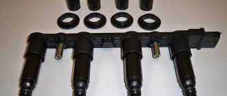
I bought new high-voltage wires: high-voltage wires with 8 valves. "Milena" 2111-3707080 For all fuel-injected VAZ cars (8kL) Resistance up to 7 kOhm How to connect.
Misfires during engine operation can be caused not only by faulty high-voltage wires, but also by failure of the ignition module. To identify a malfunction of the ignition coil on the Lada Kalina, we will need a multimeter with which we will measure the resistance at its contacts. Measurements are carried out in several stages to determine all possible faults in a particular section of the circuit. I’ll tell you everything in order below:
Replacing the ignition module with a new one
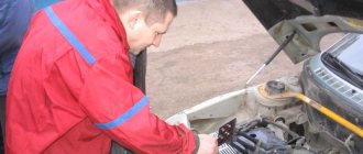
After checking the wires, no defects were found and it was decided to change the ignition module, since nothing more reasonable came to mind. In order not to waste money, they first decided to remove it from my car and check whether it was the problem. Now, a few technical details for those who will carry out similar operations, I’ll tell you what tools you will need:
- Hexagon 5 either regular or in the form of a bit attachment
- If you use a bit with a hexagon attachment, then it is most convenient to unscrew it using a ratchet rather than a regular wrench, since there is very little space near the module and it is very inconvenient to unscrew without a ratchet
It is not recommended to remove bolts with a ratchet, as you can damage the tool, and such a thing costs at least 400 rubles (in my case, with a Jonnesway ratchet). It’s not a cheap pleasure, but you can’t live without it.
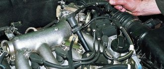
First of all, we remove the wires from the spark plugs, and you can also immediately remove them from the module itself, then disconnect the power plug that goes to the module. It sits on a latch, which works very simply, we just click on it and pull it towards ourselves. After this, you can begin to unscrew the bolts securing the ignition module on our Grant.
Then we remove the faulty module and put a new one in its place, and do not forget to put on the wires in accordance with the cylinder numbers, which are indicated on the ignition unit housing. And one more piece of advice, it is better to disconnect the battery while performing data work, in order to avoid troubles with the electrical wiring.
As it turned out later, the malfunction was precisely in the module, since after installation from my car, everything became normal and no more breakdowns in the engine were observed. We bought him a new one and installed it in literally half an hour without any technicians or service!
General information
The purpose of the Kalina ZZ is no different from other cars - turning on the ignition and controlling the engine starter. It is equipped with a mechanical interlock and protection against restarting the starter without turning off the ignition. This allows you to protect the flywheel crown and bendix from accidental turning of the key. There is also electronic protection in the form of an immobilizer, the antenna of which is integrated into the 3Z.
The Kalina ignition switch has 3 positions, each of which is described in the table.
Side lights, radio, hazard warning lights, brake lights, courtesy lamp
Car ignition system, low and high beams, heater, washer and wipers, turn signals, fuel pump.
The key can only be pulled out in the zero position. In order not to forget it in the lock, when the engine is turned off, an audible alarm is provided, which turns on simultaneously with the opening of the driver's door.
How to check the serviceability of the ignition coil?
Malfunctions of the ignition module lead to unstable engine operation and the inability to start the car. The module's task is to generate high-voltage pulses and transmit them to the spark plug (SZ). The plus of the unit receives + 12V power from the on-board network, the minus is taken from the car body.
Ignition coil for Lada Kalina
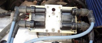
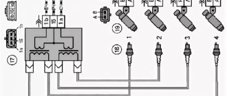
The design of the ignition module for 8 and 16 kL Lada Kalina engines includes two high-voltage transformers (coils) and two control units. One coil is connected to cylinders 1 and 4, and the second to cylinders 2 and 3. The device is connected to the SZ using high-voltage wires.
Transformers are controlled by a controller using powerful transistor valves. It receives a reference signal from the crankshaft position sensor, on the basis of which the firing sequence of the coils in the block is calculated. In addition, the controller uses information about rotation speed, coolant temperature, power unit load (mass air flow), crankshaft position and the presence of detonation. The system has no moving parts, so it does not require maintenance or adjustment.
The peculiarity of the device is that it uses a spark distribution method, which is called the “idle” spark method. The cylinders are divided into pairs. A spark is produced in each cylinder of the cylinders.
One group of spark plugs receives a spark at the moment of maximum compression of the fuel assembly (working spark), and the second at the moment of release (idle spark). Moreover, in the first case, the spark plugs are connected to the 1st and 4th cylinders, and in the second - to the 2nd and 3rd. The current in the windings of transformers constantly flows in one direction, so when sparking, the current for one spark plug flows from the side electrode to the central one, and for the second - from the central to the side.
Main signs of device malfunction:
- reduction in engine power;
- engine operation intermittently;
- intermittent idling;
- incorrect operation of paired cylinders.
If the above symptoms appear, you need to check the unit for serviceability. The cause of misfire may be the spark plugs themselves (video author - In Sandro's garage).
Before checking the operation of the unit, you should check the reliability of the connection of the high-voltage wires and the serviceability of the spark plugs. To check the motor coil of 8 or 16 cells you will need a multimeter.
Tester for verification
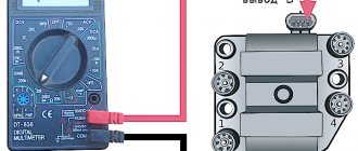
Diagnostics is carried out in several stages. First of all, the winding is shorted to ground. The multimeter must be set to check the resistance so that it works like an ohmmeter. Next, the negative probe of the tester is connected to ground - the metal part of the device body (red arrow in the photo), and the second positive probe is connected to the central contact of the transformer (blue arrow in the photo). If the resistance tends to infinity, this means that there is no short circuit and the device is working.
Checking winding short circuit
At the second stage, the primary control circuits of the coil are checked. First you need to connect the ohmmeter probes to the leftmost and rightmost terminals of the module. If the readings on the device remain the same, then there is an open circuit in the circuit. In this case, the coil needs to be replaced.
Checking the extreme conclusions
The third diagnostic stage is checking the secondary windings of the module. To check, the tester probes must be connected to the paired high-voltage terminals of the coil. First to the terminals of cylinders 2 and 3, and then cylinders 1-4, both on an engine with 16 cells and 8 cells. If the device is working properly, the ohmmeter will show a resistance of about 4 ohms, but it should not show infinity.
Checking secondary windings
Causes of malfunction
How to replace the ignition switch on a Kalina
If translated literally, “Check Engine” is an engine error, which, according to the developers, should indicate to the driver that it is worth checking this particular system. So, there are several malfunctions associated with the activation of such an alarm. Let's look at the main problems that cause a "CHECK" in the engine.
Bad fuel
Low-quality gasoline, or as it is popularly called, “bad gas,” can cause the engine warning light to appear on the dashboard. So, troubleshooting can take a lot of time and labor. In order to get rid of the effect, you will have to clean the fuel system. To do this you need to do the following:
- Remove and clean the fuel tank.
- Remove the fuel rail and wash the injectors using a special stand.
- Replace the fuel filter, because as practice shows, after low-quality fuel it becomes clogged and completely loses its service life.
Spark plug
If one of the spark plugs is damaged, Check Engine appears on the dashboard. To fix the problem, you will have to dismantle all the elements and check them for resistance, as well as visually inspect their condition. Thus, if necessary, it is worth replacing the spark plug. As practice shows, it is best to install a completely new kit, which should be pre-adjusted, check the gaps, as well as the resistance. We have already talked about the choice of candles here.
Low fuel level
When the fuel level is low, the Check Engine sign appears on the instrument panel, which may also indicate that the fuel tank cap is not closed completely and the seal is broken.
Ignition coil
The absence of a spark in the cylinders immediately signals the electronic unit, which displays the inscription “check”. This may primarily be due to the fact that the ignition coil has failed. As a rule, it cannot be repaired and must be replaced.
Oxygen sensor
A clogged lambda probe is immediately visible from the inscription on the dashboard. Here, there can only be one way out - replacement. Of course, some car enthusiasts try to clean the oxygen sensor and are quite successful, but in practice it doesn’t last long and it quickly breaks down. Therefore, it is recommended to replace it immediately.
Catalyst
The catalyst may be another reason why the Check Engine message appears on the dashboard. Usually, this is due to the high mileage of the car, so when the car starts to take oil, you should prepare for the fact that this particular part will fail. But this is not the only reason. So, bad fuel or mechanical damage will lead to the replacement of this unit.
Wiring
Cases have been repeatedly noticed that when there are problems with the explosive wire, the message Check Engine pops up. Of course, the reason should be looked for in this system and, if necessary, it is worth replacing.
ECU
The electronic engine control unit can cause a “check” to appear. Thus, accumulated errors that have not been reset for a long time may cause the dashboard to display Check Engine.
This can be treated quite simply by resetting all accumulated errors. But, as experience shows, things can get to the point where you have to change the software and flash the ECU.
The mass air flow sensor repeatedly causes the Check Engine to appear on the dashboard. In order to determine serviceability, diagnostics should be carried out. If necessary, replace this unit.
Operation in various conditions
Many inexperienced drivers, not understanding the essence of the breakdown, decide that an expensive replacement of the ignition switch or the wiring as a whole is necessary. Experienced drivers advise not to rush to conclusions. If, due to various circumstances, the ignition coil fails, the corresponding indicator lights up on the dashboard. The first thing the driver should do in such a situation is to drive the car into the garage and open the hood.
Often spark plugs fail due to a power surge or short circuit. As a result, the spark does not travel properly throughout the system. A number of other circumstances can cause a similar problem:
- the car was damaged in an accident;
- replacement of spark plugs may be required after lightning strikes the car;
- poor-quality previous repairs;
- use of non-original spare parts;
- failure to comply with technical inspection deadlines at the service center.
Regardless of the reason, the ignition circuit needs a full analysis. Often the problem is complex. That is why, if the driver does not have enough technical experience, the first decision that comes to mind should not be accepted as the only correct one.
Where is it used?
Past and present owners of VAZ “classics”, who understand the design of such cars, are well aware of the weak points and operating principles of the contact-type ignition circuit.
Its peculiarity lies in the distribution of voltage to the combustion chambers of the engine through contact connections (hence the name).
Modern cars are equipped with more modern (electronic) ignition, which is controlled by a microprocessor.
The main systems operating on the contact principle include:
- KS3 (KSZ) is the most common type of circuit, the structure of which contains a distributor, a coil and a breaker.
- KTS3 (HKZ-2, JFU4, HKZk) - ignition system with a contact sensor and preliminary energy storage.
- KTC3 (TSZi) is another type of system that operates on the contact principle. It contains a transistor and contacts, as well as an inductive energy storage device.
How to check the serviceability of the ignition coil?
Malfunctions of the ignition module lead to unstable engine operation and the inability to start the car. The module's task is to generate high-voltage pulses and transmit them to the spark plug (SZ). The plus of the unit receives + 12V power from the on-board network, the minus is taken from the car body.
Ignition coil for Lada Kalina
The design of the ignition module for 8 and 16 kL Lada Kalina engines includes two high-voltage transformers (coils) and two control units. One coil is connected to cylinders 1 and 4, and the second to cylinders 2 and 3. The device is connected to the SZ using high-voltage wires.
Transformers are controlled by a controller using powerful transistor valves. It receives a reference signal from the crankshaft position sensor, on the basis of which the firing sequence of the coils in the block is calculated. In addition, the controller uses information about rotation speed, coolant temperature, power unit load (mass air flow), crankshaft position and the presence of detonation. The system has no moving parts, so it does not require maintenance or adjustment.
The peculiarity of the device is that it uses a spark distribution method, which is called the “idle” spark method. The cylinders are divided into pairs. A spark is produced in each cylinder of the cylinders.
One group of spark plugs receives a spark at the moment of maximum compression of the fuel assembly (working spark), and the second at the moment of release (idle spark). Moreover, in the first case, the spark plugs are connected to the 1st and 4th cylinders, and in the second - to the 2nd and 3rd. The current in the windings of transformers constantly flows in one direction, so when sparking, the current for one spark plug flows from the side electrode to the central one, and for the second - from the central to the side.
Main signs of device malfunction:
- reduction in engine power;
- engine operation intermittently;
- intermittent idling;
- incorrect operation of paired cylinders.
If the above symptoms appear, you need to check the unit for serviceability. The cause of misfire may be the spark plugs themselves (video author - In Sandro's garage).
Before checking the operation of the unit, you should check the reliability of the connection of the high-voltage wires and the serviceability of the spark plugs. To check the motor coil of 8 or 16 cells you will need a multimeter.
Tester for verification
Diagnostics is carried out in several stages. First of all, the winding is shorted to ground. The multimeter must be set to check the resistance so that it works like an ohmmeter. Next, the negative probe of the tester is connected to ground - the metal part of the device body (red arrow in the photo), and the second positive probe is connected to the central contact of the transformer (blue arrow in the photo). If the resistance tends to infinity, this means that there is no short circuit and the device is working.
Checking winding short circuit
At the second stage, the primary control circuits of the coil are checked. First you need to connect the ohmmeter probes to the leftmost and rightmost terminals of the module. If the readings on the device remain the same, then there is an open circuit in the circuit. In this case, the coil needs to be replaced.
Checking the extreme conclusions
The third diagnostic stage is checking the secondary windings of the module. To check, the tester probes must be connected to the paired high-voltage terminals of the coil. First to the terminals of cylinders 2 and 3, and then cylinders 1-4, both on an engine with 16 cells and 8 cells. If the device is working properly, the ohmmeter will show a resistance of about 4 ohms, but it should not show infinity.
Checking secondary windings
Design
The lock consists of mechanical and electrical parts. Briefly about the design of each of them:
- The mechanical part is a cylindrical mechanism, which can only be turned with a key designed specifically for it. In addition, this includes an anti-theft latch that prevents the steering wheel from turning.
- The electrical part consists of terminals and contacts that close accordingly with each turn of the key. For this purpose, it is connected to the lock mechanics. There are only three contacts. One of them, the thirtieth, is supplied with plus directly from the battery. The remaining two (15 and 50) are intended to turn on consumers and the starter, respectively. To limit the current through the fiftieth contact, a relay is included in its circuit. The starter is powered through its contacts, and not through the Kalina ignition switch.
The immobilizer antenna is located in the decorative ring covering the 3Z. It responds to the transponder of the key inserted into the lock. The immobilizer recognizes only its own unique signal and gives permission to the control unit to start the engine.
How to replace the ignition module on a VAZ 1117-VAZ 1119?
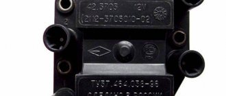
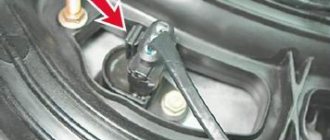
Note! We want to tell you right away, remember once and for all, if you go to a car store to buy new spare parts, be sure to look at the markings on the old ones and according to it and buy new parts, for greater clarity, first find the module where it is installed in you (Where the module is installed in Kaliny was shown above in the photo), after finding it, look at the marking on the module body (indicated by a red arrow) and write it down on a piece of paper and give it to the seller in the store before purchasing the part, if you install any other module, then the same engine operation will not guaranteed since they are all different for VAZ cars!
Removal: 1) At the very beginning of the operation, disconnect the minus terminal from the battery terminal, this is done in order to protect yourself from the module, since it produces a very huge current (Around 25,000-35,000 volts) so you need to take all precautions (It produces this current, only if you start the car), and if you don’t already know how to remove the terminal, you can read the detailed instructions about this, and it’s called: “Replacing the battery on a VAZ”, read the first point in it. 2) Then, when everything is de-energized in the car due to the terminal you removed, disconnect the four ends of the high-voltage wires from the module terminals by hand and move them to the side so that they do not interfere
2) Then, when everything is de-energized in the car due to the terminal you removed, disconnect the four ends of the high-voltage wires from the module terminals by hand and move them to the side so that they do not interfere.
Note! By the way, when you disconnect the high-voltage wires, then also disconnect the wiring block from the module; for clarity, in the photo above it is indicated by a red arrow, and it is very easy to disconnect, just press the latch that secures it and then you can disconnect the block!
How to install and tension the timing belt
- Place the timing belt on the crankshaft pulley.
- By tensioning both branches of the belt, we put the rear branch on the pump pulley and wind it behind the tension roller.
- We put the front branch on the camshaft pulley.
- Tension the timing belt by turning the tension roller counterclockwise and inserting a screwdriver (as in the photo).
- Tighten the bolt securing the generator drive pulley and turn the crankshaft by the bolt 2 turns clockwise.
- We check the coincidence of the crankshaft and camshaft marks. If the marks do not match, repeat the operation to install the belt.
Lada Kalina replacement of spark plugs. magazine Behind the Wheel
We carry out the work on a cold engine.
On a 16 valve engine
A sharp jerk upward...
A sharp jerk upward...
A sharp jerk upward...
2302-3-2-09-02 (Copy)
...remove the plastic engine casing.
...remove the plastic engine casing.
...remove the plastic engine casing.
2302-3-2-09-03 (Copy)
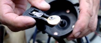
By pressing the latch of the individual ignition coil wiring harness block, disconnect the block from the coil connector.
By pressing the latch of the individual ignition coil wiring harness block, disconnect the block from the coil connector.
By pressing the latch of the individual ignition coil wiring harness block, disconnect the block from the coil connector.
2302-3-2-09-04 (Copy)
Using the E-8 head we unscrew the screw securing the ignition coil...
Using the E-8 head we unscrew the screw securing the ignition coil...
Using the E-8 head we unscrew the screw securing the ignition coil...
2302-3-2-09-05 (Copy)
...and remove the coil from the spark plug well.
...and remove the coil from the spark plug well.
...and remove the coil from the spark plug well.
2302-3-2-09-06 (Copy)
Using a high 16mm socket with an extension (or a spark plug wrench), unscrew the spark plug.
Using a high 16mm socket with an extension (or a spark plug wrench), unscrew the spark plug.
Using a high 16mm socket with an extension (or a spark plug wrench), unscrew the spark plug.
When installing the spark plug, you must screw it in by hand to avoid damaging the threads of the spark plug hole in the cylinder head.
If the spark plug does not follow the thread, strong resistance to rotation will be felt. In this case, it is necessary to completely unscrew the spark plug and, after cleaning the threads, re-tighten it.
Finally tighten the spark plug to a torque of 25–30 Nm.
Attention! Over-tightening the spark plugs can damage the threads in the spark plug holes in the cylinder head. We replace the remaining spark plugs in the same way. Replace the remaining spark plugs in the same way.
We replace the remaining spark plugs in the same way.
On an 8-valve engine
2279-4-12-01 (Copy)
Remove the wire tip from the spark plug.
Remove the wire tip from the spark plug.
Remove the wire tip from the spark plug.
Remove dirt around the spark plug.
2279-4-12-02 (Copy)
Using a high 21mm socket with an extension (or a spark plug wrench), unscrew the spark plug.
Using a high 21mm socket with an extension (or a spark plug wrench), unscrew the spark plug.
Using a high 21mm socket with an extension (or a spark plug wrench), unscrew the spark plug.
When installing the spark plug, you must screw it in by hand to avoid damaging the threads of the spark plug hole in the cylinder head.
If the spark plug does not follow the thread, strong resistance to rotation will be felt. In this case, it is necessary to completely unscrew the spark plug and, after cleaning the threads, re-tighten it.
We finally tighten the spark plug to a torque of 31–39 Nm.
Attention! Over-tightening the spark plugs can damage the threads in the spark plug holes in the cylinder head. We replace the remaining spark plugs in the same way. Replace the remaining spark plugs in the same way.
We replace the remaining spark plugs in the same way.
Error in the text? Select it with your mouse! And press: Ctrl + Enter
Engine VAZ 21114
This power unit is an injection gasoline engine with a displacement of 1600 cm3. This is a modernized version of the VAZ 2111 engine. The cylinder block is cast from cast iron, four cylinders are located in one row.
The valve train of this engine has eight valves. The injector made it possible to significantly improve the car’s dynamics and fuel economy. Its parameters comply with Euro-2 standards. The valve mechanism drive uses a toothed belt, which somewhat reduced the cost of the power unit, but requires high-quality, timely maintenance of the timing drive. The design of the piston head provides recesses that completely eliminate the possibility of damage to the valve mechanism if the timing belt is damaged or installed incorrectly. Manufacturers guarantee a motor life of 150 thousand km; in practice, it can be more than 250 thousand km.
Selected aspects of technical operation
Many inexperienced drivers, not understanding the essence of the breakdown, decide that an expensive replacement of the ignition switch or the wiring as a whole is necessary. Experienced drivers advise not to rush to conclusions. If, due to various circumstances, the ignition coil fails, the corresponding indicator lights up on the dashboard. The first thing the driver should do in such a situation is to drive the car into the garage and open the hood.
Often spark plugs fail due to a power surge or short circuit. As a result, the spark does not travel properly throughout the system. A number of other circumstances can cause a similar problem:
- the car was damaged in an accident;
- replacement of spark plugs may be required after lightning strikes the car;
- poor-quality previous repairs;
- use of non-original spare parts;
- failure to comply with technical inspection deadlines at the service center.
The ignition system can be damaged in any part of the circuit, so monitoring must be careful. It all starts with checking that the winding is properly connected to ground. It is necessary to carefully insert the contacts, focusing on the indicators of the device. Then one of the contact terminals of the device is connected to the central contact of the spark plug coil. In this case, the second contact is attached to ground.
Read more: Do-it-yourself towbar for Renault Duster - drawing and connection diagram
If an infinity symbol is visible on the multimeter screen, this indicates that there is no short circuit in this area. This should tell the car owner that the ignition circuit is in perfect order. Car owners without sufficient experience in car maintenance should be guided by the following fact. If, in addition to the infinity icon, there remains a “1” on the monitor, which was there before connection, this indicates that the section is working properly.
Replacement of spark plugs may be required if there is an open ignition in the primary circuits of the module. The device is connected to the module contacts located at the edges. In this case, the stability of the indicators on the device screen indicates that there is a problem in the Kalina ignition switch
If the fault could not be detected here, then at the next stage the car owner should pay attention to the secondary winding of the module
Take a 16-cell ignition module. and rotates so that both wire ends are facing you. A diagnostic tool is connected to the terminals of the 4th and 1st cylinders. If the faults do not manifest themselves here, then it is necessary to check the 2nd and 3rd cylinders in the same way.
Repair
Ignition module VAZ 2107
The design of the ignition module is quite complex: it includes one or more coils, a board, contacts and wires. Of all the above elements, only contact connections can be repaired; in some cases, replacement of parts (transistors, coils) is possible.
The module is dismantled and opened for repair purposes. For this you will need:
- Socket wrenches with heads 1, 13 and 17.
- Hexagon 5.
- Screwdriver.
- Soldering iron.
- Flux for aluminum.
- Stranded wire.
- Nail polish.
Opening the ignition module
Repair of the ignition module is carried out in the following order:
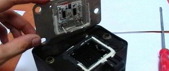
- On the removed device, open the case by prying it off with a screwdriver.
- Remove the silicone film covering the board.
- All aluminum is removed from the explosive contacts.
- On the board, new wires are soldered in place of all the dismantled old ones. To do this, the surface of the collector is cleaned of deposits, after which the board is heated to 180 o C (a characteristic smell will indicate when the desired temperature has been reached). During the soldering process, the ends of the wires are connected to the module.
- At the end of the operation, all contacts, the board and the module are covered with nail polish.
- The device is assembled in the reverse order, installed on the car and the engine is started. In case of normal operation, the ignition module is sealed tightly with sealant, while the wires are tucked inside the cavity so that they are not pinched at the edges by the plate.
If the device does not work, then a breakdown inside the module should be looked for more carefully. The transistor, electronic component may have failed, or there may be a break in the coil. Such a repair makes sense only if its price is significantly lower than the cost of a new part.
How to check the serviceability of the ignition coil?
Malfunctions lead to unstable engine operation and the inability to start the car. The module's task is to generate high-voltage pulses and transmit them to the spark plug (SZ). The plus of the unit receives + 12V power from the on-board network, the minus is taken from the car body.
Ignition coil for Lada Kalina
The design of the ignition module for 8 and 16 kL Lada Kalina engines includes two high-voltage transformers (coils) and two control units. One coil is connected to cylinders 1 and 4, and the second to cylinders 2 and 3. The device is connected to the SZ using high-voltage wires.
Transformers are controlled by a controller using powerful transistor valves. It receives a reference signal from , on the basis of which the firing sequence of the coils in the block is calculated. In addition, the controller uses information about rotation speed, coolant temperature, power unit load (mass air flow), crankshaft position and the presence of detonation. The system has no moving parts, so it does not require maintenance or adjustment.
The peculiarity of the device is that it uses a spark distribution method, which is called the “idle” spark method. The cylinders are divided into pairs. A spark is produced in each cylinder of the cylinders.
One group of spark plugs receives a spark at the moment of maximum compression of the fuel assembly (working spark), and the second at the moment of release (idle spark). Moreover, in the first case, the spark plugs are connected to the 1st and 4th cylinders, and in the second - to the 2nd and 3rd. The current in the windings of transformers constantly flows in one direction, so when sparking, the current for one spark plug flows from the side electrode to the central one, and for the second - from the central to the side.
Main signs of device malfunction:
- reduction in engine power;
- engine operation intermittently;
- intermittent idling;
- incorrect operation of paired cylinders.
If the above symptoms appear, you need to check the unit for serviceability. The cause of misfire may be the spark plugs themselves (video author - In Sandro's garage).
Before checking the operation of the unit, you should check the reliability of the connection of the high-voltage wires and the serviceability of the spark plugs. To check the motor coil of 8 or 16 cells you will need a multimeter.
Tester for verification
Diagnostics is carried out in several stages. First of all, the winding is shorted to ground. The multimeter must be set to check the resistance so that it works like an ohmmeter. Next, the negative probe of the tester is connected to ground - the metal part of the device body (red arrow in the photo), and the second positive probe is connected to the central contact of the transformer (blue arrow in the photo). If the resistance tends to infinity, this means that there is no short circuit and the device is working.
Checking winding short circuit
At the second stage, the primary control circuits of the coil are checked. First you need to connect the ohmmeter probes to the leftmost and rightmost terminals of the module. If the readings on the device remain the same, then there is an open circuit in the circuit. In this case, the coil needs to be replaced.
Checking the extreme conclusions
The third diagnostic stage is checking the secondary windings of the module. To check, the tester probes must be connected to the paired high-voltage terminals of the coil. First to the terminals of cylinders 2 and 3, and then cylinders 1-4, both on an engine with 16 cells and 8 cells. If the device is working properly, the ohmmeter will show a resistance of about 4 ohms, but it should not show infinity.
Checking secondary windings
The procedure for checking the short circuit
So, there are signs of a malfunction, you should check it.
First of all, the coil must be dismantled. For this you will need:
- prepare a ten-point socket wrench;
- disconnect the terminals on the battery;
- open the protective casing covering the motor;
- press the locking device out of the plastic, disconnect the wiring from the coil terminal;
- remove the fastening bolt;
- pull out the ignition coil.
An inspection is now underway. It should not show any cracks, melts or leaks on the caps and body parts. Only slight smokedness is allowed. Electrics can be checked in several ways. Having installed a working spark plug, we check the device for the presence of a “spark” on the car body. If there is no spark from the coil, then it is quite possible that the short circuit has lost its functionality. In such a situation, you should check the gap in the spark plugs. All work should be performed with rubberized gloves to completely prevent contact of the body or tool with the car body or engine. The fact is that the coil is capable of generating voltage in the range of 20 - 40 kV. Another option is to remove the coil and install it on a good cylinder on another car to perform a drive test. If the short circuit is faulty, it will immediately appear. The third method is instrumental.
The main reasons why the ignition coil breaks are considered to be high temperatures or overheating, which contribute to the formation of cracks. There is a high probability of short circuit failure due to the accumulation of moisture or the formation of corrosion, frequent switching on of the ignition without subsequent starting of the engine, prolonged overloads when an unsuccessful attempt to start the engine.
Removing the timing belt
You will need: remove the generator belt, the right wheel and the plastic shield of the engine compartment, prepare a “10”, “17” key, a “19” socket, and a screwdriver.
- Remove the plastic engine cover.
- Remove the timing drive protective cover by unscrewing the three fastening bolts.
- Timing diagram.
Set the piston of the first cylinder to the top dead center position:
- Turn the crankshaft clockwise by the bolt until the mark on the toothed pulley aligns with the antennae on the rear timing cover.
- Remove the window plug at the top of the clutch housing and make sure that the mark is not located opposite the scale slot.
- Secure the crankshaft from turning by inserting a screwdriver through the window between the flywheel teeth.
- Remove the bolt securing the generator drive pulley while holding the screwdriver. Remove the generator drive pulley.
- Loosen the tension roller nut. Remove the timing belt by turning the pulley so that the belt is loosened as much as possible.
- Remove the tension roller by unscrewing the nut securing it.
Have you noticed that the timing belt is eating or slipping? The reason may be a defective belt, rollers, or a pin that is overtightened.