The motor control system includes a wide range of different elements, each of which plays its own important role.
In some situations, high voltage disappears on several or even one cylinder. The reason for this may be the ignition module on the VAZ 2110, or rather its malfunction.
It should be noted that replacing the ignition module of the VAZ 2110 may not be necessary. First try to repair it, diagnose and fix the problem.
Design
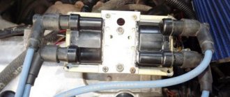
Disassembled module
Structurally, the ignition module includes two main elements:
- 2 ignition coils that generate high-voltage pulses directed to the spark plugs;
- Dual channel switch.
The reasons for failure can be different, ranging from interruptions in the operation of the engine, ending with an unexpected stop of the power unit. Please note that the "Check Engine" light does not turn on.
Ignition coils in the electronic circuit of Lada Priora
The ignition system on Priora differs from the usual traditional scheme of carburetor models. On old cars there was one ignition coil, and the direct distribution of impulses to the spark plugs was carried out by a distributor, which still needed to be configured correctly. On injection models of cars with electronic fuel injection, each cylinder has its own individual ignition coil, which sends an impulse to its spark plug for its cylinder.
The entire process is controlled by the ECU, an electronic on-board device, from which the signal goes directly to the short circuit. In order to correctly manage the injection process and timely send a signal to an electrical impulse, the ECU uses data from the following sensors:
- DPK - taking into account the position of the engine crankshaft, it supplies an impulse to the ECU;
- phase sensor - it signals the position of the camshaft, professionals call it a synchronization sensor;
- tachometer - from it a signal is sent to the ECU at what frequency the crankshaft rotates;
- Mass air flow sensor - by measuring air flow through the air filter, it determines the load on the engine at a given time;
- DTOZH - determines the engine temperature;
- DT is a knock sensor, its readings affect the ignition timing.
Under standard conditions, according to the ECU signal, the cylinders operate in the following cycle - 1 - 3 - 4 - 2. That is, the impulse for the spark arrives in those cylinders in which the compression cycle ends, before the valve opens, fuel is injected and a discharge occurs, detonation occurs and the cycle continues .
The ignition coil in the general ignition system plays the role of a low-voltage voltage converter from the on-board power supply systems, battery or generator, to high voltage. Specifically on the Priora, based on a signal from the ECU, it generates a high-voltage electrical pulse on the spark plug.
Ignition coil on PrioraStructurally, an individual ignition coil differs from a common short circuit:
- The primary winding, through which direct current flows, is located inside the secondary winding.
- There is an inner core inside the primary winding and an outer core around the secondary winding.
- High voltage, up to 40 kW, which is generated in the secondary winding, is transmitted to the spark plug not through high-voltage wires, as on carburetor cars, but through a tip, which consists of a high-voltage rod, a spring and a sheath that has insulating properties. In addition, there is a diode to quickly cut off a high-voltage pulse.
Individual ignition coils do not have any single, unified marking. Each manufacturer has its own designation system for electronic parts. Therefore, we must proceed from which short circuits are in greatest demand among Priora owners.
One of the most popular brands is BOSCH. These ignition coils are marked - 0 221 504 473 (also found 0 221 504 461). It is believed that such reels should cover 100 thousand kilometers without failure, although in fact this is not always the case.
Very often this happens due to the large number of counterfeit spare parts on the automotive market. Just ask how much an ignition coil costs for a Priora. The price of 1,150 rubles is not the highest, and they are sold in large wholesale for 850 rubles apiece. Of course, this is a tasty morsel for garage workshop dealers.
Interesting in this sense is the experience shared by one of the specialists who specifically studied this sensitive issue. He tells how the original IKZ differs from the fake one. He had a Priora and gave us examples of how to check the ignition coil:
- Under the casing there is a plastic housing.
- There is a “lightning” sign, as a designation of high voltage, near the mounting axle box.
- The surface of the plug is perfectly processed, the font on it is clear, it is applied using a laser, so minor melting is visible.
- The plant number is circled in an oval.
- The contact spring has tight coils made by the factory machine.
- The body is made of metal.
- The lightning bolt sign is missing.
- The surface of the plug is roughly processed, the inscriptions are stamped, the rubber tip lacks the date of manufacture, product number and Bosch brand name.
Malfunctions
Diagnosing the problem will not be a problem for you if you understand a little electrical engineering and know how to work with a device such as a multimeter. If not, we recommend that you contact a specialist. A professional check of the ignition module of a VAZ 2110 using a multimeter will give you the result you need and will allow you to answer important questions.
Do not rush into repairs, since the problem may not lie in this element at all. Before checking the ignition module on a VAZ 2110, consult with professionals and arrange a check of your car. You will have to spend time and money on this, but it is better to be prepared for troubles.
Before checking the VAZ 2110 ignition unit, make sure that all other engine systems are working properly.
Quite often, short-term breakdowns occur in the system, which soon disappear. The check engine light does not detect them, but they remain in the controller and are entered into its memory. If you try to read errors on the controller with a tester, it will not show anything, since there were problems, but now they are gone.
We have already become familiar with the signs of a malfunction in the VAZ 2110 ignition module, and the reasons for such situations may be dirty contacts, poor ground connection, electrical interference, and so on.
Checking the ignition module of the injection VAZ 2110 8/16 valves
Content
The top ten may have an eight-valve engine 2111, with a volume of one and a half liters, or an engine 21114, with a volume of 1.6 liters. The difference between them is in the ignition modules.
The module for a one and a half liter engine has the article number 2112-3705010, and the module with a volume of one thousand six hundred cubic meters has the article number 2111-3705010. They also differ in price. If the cost of the first ranges from one and a half thousand rubles to 2100, then the cost of the second is cheaper by about five hundred rubles.
Which one should you choose? The most reliable ones are produced in the city of Stary Oskol.
Module structure
It consists of two ignition coils and two high-voltage switch switches. The coils are designed to create high-voltage pulses.
In essence, it is a simple transformer that has two windings: a primary winding, with an induction voltage of approximately five hundred Volts, and a secondary winding, with an inductive voltage of at least twenty kiloVolts. Everything is placed in one housing with one connector for signal wires and four for high-voltage.
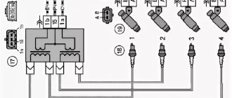
Schematic diagram of the VAZ 2110 module
The operation of the ignition module is based on the “idle spark principle”. The module is capable of distributing a spark in pairs: to the first and fourth, second and third cylinders when transmitting pulses from the electronic control unit.
Possible faults
You can ring the VAZ-2110 ignition module yourself.
The main task of the module is to supply current to the spark plugs. A high-quality spark is enough to ignite the working mixture. If there is no spark, then problems with the engine are inevitable in the form of a decrease in power, an increase in fuel consumption, dips during acceleration, the speed fluctuates, and the engine refuses to work during startup.
Symptoms and check
If one coil fails, two cylinders stop functioning. This is easy to notice, since the engine becomes heated at idle, starting is difficult, gasoline consumption increases sharply, and dynamics are lost.
We remove the connector from the VAZ 2110 module by slightly moving the latch and pulling the wire.
We check the voltage between pin 15 and the block ground.
Circuit for checking the primary windings
Secondary winding test circuit
Scheme for checking the module for short circuit
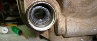
You need to make sure the spark plugs are working. They are unscrewed and the spark is checked separately on each of the spark plugs. A high-voltage wire is placed on the spark plug head. The spark plug is placed in such a way that the threaded part of the spark plug and the engine mass are in contact. If, when cranking the engine with the starter, the spark is very weak or absent altogether, then it needs to be replaced. If there is no result, you need to check the high-voltage wires. This excludes spark plugs, caps and high-voltage wires from the list of faults. This means it’s time to move on to checking the ignition module. How to do this?
First of all, the body is carefully inspected, the surface of which must be intact. If chips, cracks or burns are detected, then the module must definitely be replaced.
If spark instability is noticed only on the first and fourth, or second and third cylinders, then the conclusion arises that some coil is damaged.
Even if this is the case, due diligence needs to be done.
Checking the VAZ-2110 ignition module with a multimeter 8 valves is as follows:
- The connector with signal wires is disconnected from the module.
- It is then removed from the module. The latch must be moved to the side and pulled by the wire.
- The ignition is turned on to check the voltage at the terminal of the central block of control wires. If there is no voltage when the battery is charged, or if the value is less than the nominal value, which is twelve volts, it is concluded that the electronic control unit is faulty.
- The high-voltage wires are removed, and it is necessary to unscrew and remove the module mounting bots.
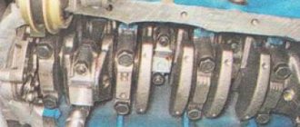
- The resistance on the primary windings of the coils is checked. The multimeter is set to resistance measurement mode. Using the device, readings are taken from the rightmost and central terminals, then the leftmost and central ones are checked. The nominal resistance should be about 0.5 ohms.
- The primary windings are checked. The resistance in the secondary windings is measured between the terminals of the first and fourth, second and third high-voltage wires. Nominal resistance 5.4 kiloohms. If a discrepancy is found, it means that the coil is not operating correctly.
- The module is checked for a short circuit. One of the tester probes is installed on the central terminal, the other on the metal body. If there is no indication of a short circuit, a conclusion is drawn that the housing of one of the coils is short-circuited.
Errors
The error scanner detects a module malfunction. If the error codes are P-3000, P-3001, P-3002, P-3003 and P-3004, this is a lack of sparks. This means that the problem is either in the module itself, or the spark plugs are faulty, or the high-voltage wires, or the electronic control unit.
If the error code is P-0351, then the coil of the first to fourth cylinders is faulty, with the code P-0352 the second to third.
Such a scan does not say anything about the functionality of the module. The problem may be in the spark plugs or broken high-voltage wires. But if they were diagnosed before testing, then the ignition module is definitely to blame.
Here the car owner makes the decision. Only he can decide to repair it himself, or buy a new one. Choosing the second option will be simpler and faster, guaranteeing uninterrupted operation of the ignition system.
Repair
So, for the VAZ 2110 the most common problem is the disappearance of voltage on cylinders 2 and 3. After some time, the engine starts working normally again if you press the rear plate of the module.
You should not put up with such a situation; it is better to immediately check the functionality of the unit, restore or replace it completely.
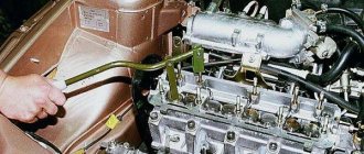
Removing the module
The procedure is quite simple.
- Disconnect the negative cable from the battery.
- Remove the plastic cover that covers the motor.
- Remove the wires from the spark plugs.
- Disconnect the wires from the ignition module. Their numbering is indicated on special white rings. And the cylinder number is indicated on the ignition module housing.
- Disconnect the connector from the ignition module.
- Using a 10mm socket, unscrew the three nuts that hold the block we are looking for.
- Carefully remove it, after which you can begin further work.
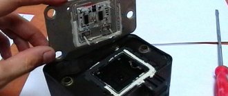
Now let's move directly to working with the module:
- Open the aluminum plate on the ignition module. A flathead screwdriver is useful for this.
- Inside you will find a small printed circuit board with electronic components. It is covered with a transparent layer of silicone, which will have to be removed.
- There are also wires that connect the board to the connector contacts. They are made of aluminum, so they can tear quickly.
- Tear off all the wires from the contacts, don’t be afraid. Others will be installed in their place. By the way, experts recommend using stranded wires used in computer mice.
- The ignition module circuit includes two switches and two powerful transresistors. If you decide to change these elements, you need to know that the switches are manufactured by SGS-THOMSON (model L497D1), and the transistors are of the BU931 type.
- The contacts are made of aluminum, so you will need a special flux to work with this metal.
- We solder the wiring to the board. It is more difficult to solder to the transistor collectors, since they are covered with a special material, the soldering of which is problematic. Therefore, try to hide the top coating from the element as carefully as possible. To prevent the soldering iron from transferring all the heat to the plate, place it on the stove and heat it to 180 degrees Celsius.
- Solder the wires to the contacts on the module so that they are as short as possible.
- Cover the areas where you soldered with varnish. Regular nail polish borrowed from your wife will do.
- Check if the ignition module is working.
- If everything is fine, coat the inner surface with a special autosealant, then reassemble in the reverse order.
- Upon completion of assembly, the wiring should be positioned fairly freely. Make sure that they are not compressed inside the box and that the integrity of the connections is not broken.
Carrying out such a repair of the ignition module on a VAZ 2110 with your own hands will not be difficult. But be careful, act carefully and consistently. Pay special attention to the soldering process.
But keep in mind that we have addressed the problem of bad contacts. She is not the only one for the “ten”. You may need to pinout the ignition module on the VAZ 2110. For this, it is better to contact specialists.
If the cause of the malfunction lies elsewhere, then there is a high probability that it is better to simply replace the VAZ 2110 8-valve ignition module with a new one. The search may drag on without yielding results. Replacing the element will completely solve the current problem.
Types and differences of VAZ ignition coils
A car's gasoline engine operates by burning fuel. To ensure ignition, an electric spark is required, which is formed between the electrodes of the glow plug. They have a small gap that the spark must overcome. This is feasible when high voltage (tens of thousands of volts) is applied to the spark plug.
The vehicle's on-board system is not designed for such loads, and the equipment that supplies electricity is not capable of producing such values.
To solve this problem, a coil is introduced into the car's ignition system, creating a high voltage. A component of the vehicle's ignition system converts low voltage to high voltage (depending on the characteristics of the part from 6-12 V to 35,000 V). The tasks performed by the coil are determined by the structural features of the element. It consists of primary and secondary windings, which are housed in an insulated housing.
Attention! If malfunctions occur, it is recommended to check all engine components: from the valves and cylinder block to the ignition coil or module
Classic, family 2101-2107
Domestic VAZ cars of the “classic family” (models 2101-2107) are equipped with carburetor and injection engines. Cars with carburetors have an ignition coil (or "bobbin") installed. The arrangement of the element is as follows: the part is mounted on the left mudguard in the engine compartment of the car, and is attached to the body using two nuts.
Cars with installed injectors (VAZ 2107) have an ignition module. It is mounted on the cylinder block of the car's power unit. The part functions together with the engine's electronic control unit, and the ignition coils are included in the design of the entire module.
The ignition module used is a universal model (installed on other domestic cars)
For the injector and as part of the BSZ, a coil 027.3705 is used, analogous to 27.3705 (ATE-2).
The characteristics of the “injection version” of the VAZ ignition coil are as follows:
Operating temperature from -40° C to +85° C Resistance value: primary winding (0.45+0.05) Ohm secondary winding (5+0.5) kOhm Supply voltage 12 V Overall dimensions 72x156 mm, oil-filled design
Tenth models, 2110-2112
On the VAZ 2110-2112, ignition coils are installed on both injection and carburetor engines (nowadays they are practically not found). For injection models VAZ 2110-2112, an ignition module marked 042.3705 is provided, designation according to the documentation of OJSC AvtoVAZ 2112-3705010-03, some models are equipped with individual coils 2112-3705010-12
Lada Samara, 2113-2115
On carburetor models of VAZ cars of the Samara family (2113-2115), ignition coils 2111.3705 (analogous to Bosch F000 ZS0 211) are installed. These coils have a 3-pin connector and are used for VAZ cars with a microprocessor internal combustion engine control system based on the M7.9.7 controller or its analogues with 8-cl. engines.
Kalina, 1117-1119
A more modern VAZ model, Lada Kalina, is equipped with an ignition module marked: 2112-3705010-12. It has the following characteristics:
Load voltage 1MΩ +25pF>24kV
Spark charge duration 1.14-1.5 ms
Operating temperature range from -40 to +140 degrees C
Rated supply voltage 12V.
Priora, 2170-2173
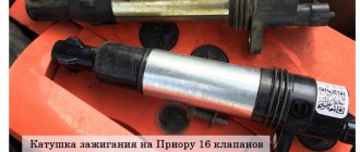
The Lada Priora is equipped with the same ignition coils as the Kalina. The coil is marked 2112-3705010-12. Just as in the case of Kalina, Priora is equipped only with injection engines, so carburetor ignition coils or “bobbins” cannot be installed on the car.
A little about prices
We have already noted which switch and transistor are used when repairing the ignition module of a dozen. The first costs about 3 dollars, and for the second you will have to pay about 6 dollars.
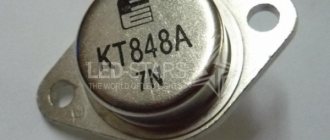
Some craftsmen use a domestic analogue of the transistor - model KT848A . Of course, it costs less. But its problem is its lower quality and larger size, which somewhat complicates the repair process.
Checking a faulty ignition coil on a Priora
Any modern car, and the Lada Priora in particular, consists of a body as a formative platform and many units and systems specially installed in this body, which together create an individual model of the car. One such system is the ignition system.
A stable start and smooth, uninterrupted operation of the entire engine depend on its correct installation, high quality parts and sufficient compatibility with other vehicle components. After all, it is through the elements of this system - the ignition coils and spark plugs - that a high-voltage pulse is supplied in the form of a spark to ignite the fuel injected into the cylinder chamber.
Contactless engine ignition system 2110
Diagram of a contactless ignition system.
The contactless ignition system consists of an ignition distribution sensor 2, a switch 4, an ignition coil 1, spark plugs 3, an ignition switch 5 and high voltage wires. The power supply circuit for the primary winding of the ignition coil is interrupted by an electronic switch. Control pulses are supplied to the switch from a contactless sensor (Hall sensor) located in the ignition distributor sensor.
Ignition distributor sensor - type 40.3706 or 40.3706–01, four-spark, unshielded, with vacuum and centrifugal ignition timing regulators, with a built-in microelectronic control pulse sensor (Hall sensor).
Switch – type 3620.3734, or 76.3734, or RT1903, or PZE4022. It converts the sensor control pulses into current pulses in the primary winding of the ignition coil.
Ignition coil - type 3122.3705 with a closed magnetic circuit, dry or type 8352.12 - oil-filled, sealed with an open magnetic circuit. Spark plugs - type A17DVR, or A17DVRM, or A17DVRM1, or FE65PR, or FE65CPR with noise suppression resistors.
Ignition switch - type 2110–3704005 or KZ–881 with an anti-theft locking device, with a lock against re-starting the starter without first turning off the ignition and with an illuminated socket.
The ignition system of the 2110 engine is an injector.
The VAZ 2110 injection engine control system is a group of complex electronic and mechanical devices that require certain knowledge and approaches to repair. It consists of a set of sensors, actuators and a central control unit - the controller.
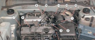
Location of elements of the injection engine control system 2111
- mass air flow sensor;
- coolant temperature sensor;
- knock sensor;
- adsorber for gasoline vapor recovery system;
- crankshaft position sensor;
- throttle pipe (it contains a throttle position sensor and an idle speed regulator);
- speed sensor (located on the gearbox);
The principle of operation of the ignition coil
Before we talk about how to remove, how to change and how to connect a short circuit with your own hands, let's understand the principle of its operation. Structurally, this device includes two windings - primary or secondary. The first involves 100 to 150 turns of thick copper wire, which must be insulated to prevent voltage surges. It is also equipped with two low-voltage cables located on its cover.
As for the secondary, it can include from 15,000 to 30,000 turns of thin copper wire, this winding is located inside the primary. One end of it is connected to the negative terminal of the primary element, and the other to the central terminal on the cover. It ensures the transfer of high voltage charge. Both windings are located around a metal core, the entire structure is enclosed in an insulated housing. To prevent current heating, a lubricant is used for the coils, in particular, we are talking about transformer oil, which fills the housing.
The principle of operation of a short circuit is based on the formation of a high-voltage charge in the secondary winding when a low-voltage current passes through the primary component. When current passes through the primary winding, a magnetic field is created in the system. When the current is cut off, the magnetic field forms a high-voltage voltage in the secondary component, which is transmitted through the connector and using a distributor to the spark plugs.