VAZ-2114 ignition module and its features
The passenger car ignition module is specially designed to improve the starting of a car engine.
Since two high-voltage coils operate as the main components of the module, it is often called the “ignition coil”. Let's look at the structure of this part:
- coils for generating high voltage;
- two-channel electronic switch;
- durable plastic case;
- low-voltage connector for supplying control pulses;
- terminals for connecting high-voltage wires to spark plugs.
The main operating elements of the ignition module are high-voltage coils that distribute the igniting spark to the spark plugs. This is possible thanks to the following design:
- Wires for high voltage transmission.
- Low voltage terminals.
- The windings on the core are secondary (for igniting the working mixture) and initial.
- Electrical steel core.
The mechanism of operation of the ignition coil is as follows:
- the electronic engine control unit collects all signals from the sensors located on it;
- The ECU generates a control signal;
- the signal goes directly to the ignition coil;
- that, in turn, forms a high-voltage voltage;
- voltage from the coil is supplied to the engine cylinder spark plug;
- the fuel-air mixture ignites;
- the engine starts.
Even an inexperienced car enthusiast can find this part: just trace the path of one of the high-voltage wires - from the spark plug to the plastic case.
This housing houses the ignition module.
PRINCIPLE OF OPERATION OF THE MODULES
The VAZ ignition module is an improved engine starting system. The principle of its operation is not very different from conventional systems. If in older systems the high-voltage voltage was generated by opening the contacts in the ignition distributor, then in the module the signals from the control unit serve as a pulse generator.
The control unit collects signals from sensors on the engine, generates a control pulse and sends it to the ignition module of the VAZ 2115. In it, a high-voltage voltage is generated from the on-board network voltage and sent to the cylinder spark plug to ignite the air-fuel mixture.
VAZ-2114 ignition module: various signs of malfunction
Experts note the main symptom of a faulty ignition coil is the absence of an igniting spark on the spark plugs. But, besides this, there are other signs by which one can judge that the module has failed:
- Lack of dynamics during engine acceleration.
- The appearance of failures in the operation of a car engine at the moment of sharply pressing the gas pedal with your foot so that the vehicle accelerates.
- A noticeable decrease in engine power (as they say, “the engine doesn’t pull”).
- “Swimming” of idle speed.
When the first signs of a malfunction of the described module appear, the owner of the VAZ-2114 should diagnose it. This can be done either independently at home or at the nearest service center for repairing cars of this model.
GENERAL INFORMATION
Most of the units we are considering are located in the engine compartment. We present to your attention a diagram of the arrangement of sensors on the VAZ 2114 engine:
The location of the sensors must be known to the responsible motorist
- Camshaft position (phase sensor);
- Coolant temperature;
- Detonation;
- Oil pressure;
- Oxygen sensor (lambda probe);
- Kneeshaft position;
- Speed;
- Idle move;
- Mass air flow;
- Fuel level;
- Gasoline level;
- Antifreeze level;
- Throttle Positions
Now let's look at the sensors and their location in more detail.
CRANKSHAFT POSITION SENSOR
DCP is a device that supplies the computer with information about the position of the crankshaft. The correct functioning of the fuel mixture supply and ignition systems, as well as the injectors of the injection engine, depends on the operation of this unit.
This device is often called a synchronization sensor, since the ECU, based on information received from the DCPV, determines the moment of fuel injection into the engine cylinders. If the DCPV breaks down, incorrect information will be supplied to the brains of the fourteenth and the engine will lose its performance, since there will be malfunctions in the fuel supply system and the injectors will not be able to function normally.
On the fourteenth, inductive type DCPVs are installed, the approximate cost of a new device is 150 - 200 rubles. The DCPV is located near the alternator belt, near the camshaft.
CAMSHAFT POSITION SENSOR
DPR is often called a phase sensor. This device is available on all fourteen cars with 16-valve engines, and on VAZ-2114 with 8-valve engines with phased injection of the fuel mixture.
The DPR transmits data about the current operating cycle of the power unit to the ECU:
- Which valve is open?
- What valve timing is being implemented at the moment.
Based on the information received, the ECU determines the timing of fuel injection so that gasoline is supplied just before the intake valve opens.
The device is located on the engine, near the cylinder head, not far from the air filter.
Phase sensor for VAZ 2114
THROTTLE POSITION SENSOR
TPS is one of the key devices, the correct functioning of which depends on the operation of the fuel system. As the name implies, TPS transmits information to the brains of the fourteenth about at what angle the throttle valve is placed at a particular moment in time
One of the main characteristics of the TPS is the signal frequency, based on the change in which the engine control unit determines the degree of pressure on the gas pedal, which allows the brain to select the optimal engine cooling mode and the amount of fuel supplied.
TPS is part of the throttle assembly. It is located on the throttle body, next to the idle speed sensor.
KNOCK SENSOR
A properly functioning DD is the key to the normal functioning of the fourteenth engine. If it breaks down, the engine will run rough and gas mileage will increase.
The DD reacts to engine vibrations, information about which is transmitted to the ECU, which allows the ECU to select the correct ignition timing (the moment of ignition of gasoline in the cylinder).
The device is mounted on the engine cylinder block next to the fan, between the 2nd and 3rd cylinders.
COOLANT TEMPERATURE SENSOR
DTOZH (also referred to as the VAZ 2114 engine temperature sensor) is located at the place where the inlet pipe is located on the body of the cylinder cooling system, to which the antifreeze supply pipe is connected.
How to diagnose the ignition coil on a VAZ-2114
As already mentioned, when the first signs of malfunctions appear in the VAZ-2114 ignition module, the vehicle owner should diagnose it. You can perform a similar procedure yourself at home using the following algorithm:
At home, all stages of the checks can be performed independently. The first stage is checking the spark plugs. It is carried out in the following sequence:
- We remove the spark plugs from their sockets - remove the tips of the high-voltage wires (a special spark plug wrench is suitable for this).
- We examine the candles.
- We clean them from possible soot.
- We set the correct distance between the electrodes.
- We check the spark plugs for operation using improvised means (for example, from a device made from a piezo lighter) or on a car engine with a working ignition system.
If the spark plugs are in good condition, you can proceed to the next stage of checking for faults in the ignition module.
The second step is to check the crankshaft sensor. This test is carried out using a multimeter, thanks to which two characteristics are checked - voltage and resistance. To do this proceed as follows:
- Remove the crankshaft sensor.
- Measure resistance:
- a special ohmmeter mode is installed on the device;
- the terminals of the device are connected to the ends of the winding, which is brought to the surface;
- with optimal sensor operation, digital readings will range from 500 Ohms to 700 Ohms.
- Measure voltage:
- switch the device to the mode for measuring alternating voltage;
- terminals are connected to the ends of the winding;
- any handy object made of metal should be passed along the body of the crankshaft sensor;
- When the sensor operates optimally, the device will show increased voltage readings because there will be a metal object nearby.
Otherwise, the faulty sensor will have to be replaced with a new one, because it also affects the operation of the VAZ-2114 ignition module. If after this there are still signs of coil malfunction, then you should proceed to the third stage of the test.
The third stage is checking the ignition coil itself. This part is checked as follows:
- The easiest way is to replace the coil with a new one;
- while the car engine is running, you can move the coil and knock on it (if there are visible changes in the functioning, it is time to judge a faulty contact in the coil itself);
- take measurements with a multimeter for resistance readings, such indicators are taken from paired coils - they should be identical, approximately equal to 5.4 kOhm.
What to do if you don’t have a multimeter, but you need to check the electrical circuit? Experts recommend using a twelve-volt light bulb. To do this, one of the wires coming from it should be connected to the terminal, and the second wire should be shorted to the motor housing. If the control light flickers when the starter starts, then everything is in working order.
If the car owner has problems performing such diagnostics himself, he can always turn to qualified specialists at a service station.
How to replace the temperature sensor?
You can replace the part yourself without resorting to the help of specialists. For ease of dismantling, it is better to choose a socket wrench or a deep socket with a knob.
Replacement is carried out on a cold engine in the following sequence:
Remove the air filter from the car. It blocks access to the sensor. After replacement, you will need to install the filter in its seat. Disconnect the negative cable from the battery. Necessary to avoid errors in the electronic control unit. Remove the protection located under the power unit. Drain the coolant from the radiator. Disconnect the wires from the sensor
When disconnecting the connector, it is important not to damage the plastic latch. It is necessary to fix the plug and prevent it from spontaneously disconnecting.
- Unscrew and replace the sensor. A 19 mm socket wrench is used. To speed up the work process, you can use a head with a ratchet.
- Reinstall the electrical wiring plug and protection.
- Fill with coolant and warm up the power unit to operating temperature.
Some car owners replace the sensor without draining the coolant. To do this, carefully unscrew the part and quickly replace it with a new one. Thus, during the replacement process, a minimum amount of coolant leaks.
Methods for preventing the ignition module on a VAZ-2114
Malfunctions of automobile ignition coils on the VAZ-2114 can be avoided if preventive procedures are regularly carried out. These include:
- Periodic unraveling of high-voltage wires (associated with greatly increased internal resistance, as this can damage the module).
- Checking the spark gap between the electrodes of the spark plugs (if the distance between the electrodes changes, this will affect the efficient operation of the ignition coils).
If faulty spark plugs are identified, they are replaced, after which the car will function properly again.
Source
Video: VAZ 2114 sensors - what they are and what they do
Signaling devices called sensors are installed in order to inform the driver or some control device about changes occurring during the operation of the car or about the state of the corresponding unit or system, as well as to signal in case of failures or emergency conditions in the car. Therefore, the driver must have a good understanding of the operating principle and location of the sensors on the VAZ 2114.
- The oil level has dropped significantly;
- the oil filter is clogged;
- the oil pump has failed;
- oil pressure sensor is faulty;
- The wiring is faulty or the oil pressure has dropped due to leaks.
On an eight-valve engine, the sensor is located on the right side below the valve cover in the cylinder head. On a sixteen-valve engine - on the left end of the camshaft bearing housing.
Where is the coolant temperature sensor located on the VAZ 2114
For proper operation, ensuring the collection and transmission of optimally accurate indicators, the DTOZH must be located in direct contact with the measured medium, that is, it must be immersed in the coolant.
Let's look at a temperature sensor using the example of one of the cars in the Lada model range.
The cooling system of VAZ cars is a complex of the following parts:
- heating and cooling radiators;
- fan;
- pump;
- expansion tank;
- coolant temperature sensor.
The measuring device, located between the thermostat and the cylinder head, consists of a resistor and is connected to the control unit by two wires.
We check the ignition module on the 8-valve VAZ-2114 with our own hands: signs of malfunction
- VAZ 2114 ignition module and its purpose
- Possible reasons for failure of the ignition module
- Signs of coil malfunction
- How to check the malfunction of the VAZ 2114 ignition module on your own?
- Ignition module repair
- Useful video
A faulty ignition module (“coil”) is often to blame for engine malfunctions, instability of speed, and poor acceleration. How it works, how to check the ignition module of a VAZ 2114 and how to replace it in case of a malfunction will be discussed in this article.
Engine management system
In general, the entire engine control system consists of two components:
By “brains” we mean an electronic control unit, or in short “ECU”, “brains”, “computer”. As they were produced, injection VAZs were equipped with different ECU models - Bosch, January, Avtel/Itelma. To learn more about the brains, the main problems, which brains were installed in certain years, the possibility of chip tuning, read the detailed article - ECU. What it is?
The brains take readings of the current state from the sensors, analyze and control the operation of the engine using the same sensors. Now let's talk about the sensors themselves that are involved in engine operation:
- Crankshaft position sensor (CPS) - serves to synchronize engine operation with the operation of the ECU, works on the principle of induction. In the event of a malfunction, the car does not start well, does not pull, ... More details in the corresponding article.
- Camshaft position sensor (CPR) - often called the “Phase sensor”. Serves to determine phased injection. It is possible to work with a faulty sensor. In details .
- Throttle position sensor (TPS), or gas pedal position sensor (if the gas pedal is electronic, installed since 2011). As for the DPZ, it is paired with the IAC. TPS determines the degree of opening of the throttle assembly. If this sensor is faulty, then there is no response to the gas pedal, the speed increases spontaneously, etc. More details in the corresponding article.
- Knock sensor (DS) - the name speaks for itself. The knock sensor detects engine vibrations (detonation) and accordingly advances the ignition angle. More details in the corresponding article.
- Coolant temperature sensor (Dtozh) - in other words, an engine temperature sensor. Installed on the thermostat, designed to control the temperature conditions of the engine. For more details on how to replace and check, see the article.
- The mass air flow sensor (MAF) is the most expensive sensor, so its failure is extremely unpleasant. Using this sensor, the ECU reads the amount of air consumed. The main malfunctions are lack of traction from the engine, problems with idling. On this site, good informative articles are devoted to this sensor, which you can read.
- Speed sensor (DS) – the speed sensor is primarily designed to measure the speed of the vehicle and is located on the gearbox. But it also has other functions - more on that.
- Oxygen concentration sensor, or simply oxygen sensor (dk) - determines the amount of oxygen in the exhaust system, regulates the mixture of fuel and air. Euro-2 has 1 sensor installed, Euro-3 has two sensors. Very often, after 60 thousand km. The second mileage sensor is disabled by software because With our gasoline it quickly breaks down. However, it can be repaired and replaced. DC is also the cause of many problems, more about this.
- Idle air control (IAC) (until 2011) or an electrically driven throttle valve (since 2011) - this sensor is responsible for stable idling. Allows air into the engine at idle speed, bypassing the TPS. Quite a capricious sensor, we replace it often. The main problem is unstable idle. Often there is a marriage. More about this.
- Electric throttle valve - (E-gas) - the essence is that it is an electronic throttle valve, which is opened not by the gas pedal cable (mechanically), but by the brains (electronically).
- Gas pedal position sensor - (E-gas) - the sensor provides readings of the gas pedal position to the computer, which in turn opens the electronic throttle valve.
As you can see, in general the number of sensors is not large, but believe me, many of them have caused many problems to car owners, so carefully study and use this material.
Examination
It is a mistake to assume that damage to high-voltage wires does not in any way affect the condition of the module itself. Many people think of simply replacing high-voltage elements, but in reality they will still have to change the module.
This is explained by the fact that damaged or defective wires direct the wrong current, the configuration of which does not correspond to the necessary parameters. As a result, the spark hits inaccurately or ineffectively, causing the module to burn out and become unusable.
In general, the best option for checking the ignition module on a VAZ 2114 is to use an oscilloscope . But, firstly, not every driver has it, and secondly, few people can use them. Therefore, we will carry out the check using improvised means:
- 12-volt light bulb;
- Tester (available for little money at any auto parts store).
Let's start with preliminary manipulations with the accompanying elements of the ignition module.
- Check the wiring harness. It is disconnected and the voltage indicator is checked.
- To do this, fix the tester on contact A, and connect the other terminal to engine ground.
- In normal condition, the voltage reading will be 12V.
- If there is no voltage, most likely the fuse has blown.
- If everything is fine, transfer the terminals of your tester to contacts A and B, start the car. In this case, the starter should turn and the 12-volt light should blink.
- In the absence of these phenomena, we can talk about the presence of a break in circuit A of the contacts.
Next we go to the ignition module itself.
There are several ways to check the condition of your unit. Therefore, let's look at each of them.
- Set the tester to ohmmeter mode. Use it to measure the resistance on the high-voltage lines going to cylinders 1 and 4, and then, by analogy, to the wiring of cylinders 2 and 3. In normal condition, the device will give you readings from 5.2 to 5.5 ohms.
- Give the device a gentle tug. Thus, you will shake the wiring block and the module. Moreover, this must be done in the operating mode of the power unit. If the device works without obstruction when loosened, everything is fine, you are lucky. If not, you will again have to study the condition of the wiring.
Third way
The third method is considered the simplest, since it involves replacing your device with a similar one that works exactly. But to do this, you have to find a full-fledged twin. We are talking about an ignition module from a car similar to yours in terms of year of manufacture and power unit used. It’s just that 1.5-liter engines have modules, and 1.6-liter engines have coils.
But to replace a module with a module, you will have to first dismantle yours. This is done as follows:
- Remove the negative terminal from the battery, which will allow you to turn off the power to the car;
- Disconnect four high voltages from the ignition module;
- Disconnect the wire block. To do this, you need to release the special clamp that holds the block on the module;
- Next, unscrew the three nuts. With their help, the module is held on the bracket;
- There are three long pins on the bracket, from which the module can simply be pulled off.
Having dismantled your module, you can put another unit in its place, thereby verifying the functionality of that one and the malfunction of yours.
Oxygen sensor (lambda probe)
Oxygen sensor
Installed in the exhaust pipe of the exhaust gas system. The oxygen contained in the exhaust gases creates a potential difference at the sensor output, varying from approximately 0.1 V (a lot of oxygen - a lean mixture) to 0.9 V (a little oxygen - a rich mixture). Based on a signal from the oxygen sensor, the controller adjusts the fuel supply to the injectors so that the composition of the exhaust gases is optimal for the efficient operation of the converter (oxygen sensor voltage is about 0.5 V).
For normal operation, the oxygen sensor must have a temperature of at least 360°C, so for quick warm-up after starting the engine, a heating element is built into it. The controller constantly supplies a stabilized reference voltage of 0.45 ± 0.10 V to the oxygen sensor circuit. Until the sensor warms up, the reference voltage remains unchanged. In this case, the controller controls the injection system without taking into account the voltage at the sensor. As soon as the sensor warms up, it begins to change the reference voltage. Then the controller turns off the heating of the sensor and begins to take into account the signal from the oxygen sensor.
The sensing element of the oxygen sensor is located in the exhaust gas stream. When the sensor reaches operating temperatures exceeding 360 degrees. C, it begins to generate its own emf, proportional to the oxygen content in the exhaust gases. In practice, the DC signal (with a closed feedback loop) is a rapidly changing voltage, fluctuating between 50 and 900 millivolts. The change in voltage is caused by the fact that the control system constantly changes the composition of the mixture near the stoichiometry point; the DC itself is not capable of generating any alternating voltage.
The output voltage depends on the oxygen concentration in the exhaust gases in comparison with the reference data on the oxygen content in the atmosphere coming from the sensor design element that serves to determine the atmospheric oxygen concentration. This element is a cavity connected to the atmosphere through a small hole in the metal outer casing of the sensor. When the sensor is in a cold state, it is not able to generate its own EMF, and the voltage at the DC output is equal to the reference (or close to it).
To speed up the heating of the sensor to operating temperature, it is equipped with an electric heating element. There are sensors with constant and pulsed power supply to the heating element; in the latter case, heating of the DC is controlled by the ECU. The electronic control unit constantly supplies a stable reference voltage of 450 millivolts to the sensor circuit.
An unheated sensor has a high internal resistance and does not generate its own EMF, therefore, the ECU “sees” only the specified stable reference voltage. As the sensor warms up while the engine is running, its internal resistance decreases, and it begins to generate its own voltage, which overlaps the stable reference voltage supplied by the ECU. When the ECU “sees” the changing voltage, it knows that the sensor has warmed up and its signal is ready to be used to regulate the mixture composition.
The oxygen sensor used in serial injection systems is not capable of recording changes in the mixture composition that differ markedly from 14.7:1, due to the fact that the linear portion of its characteristic is very “narrow” (see graph above in the text). Beyond these limits, the lambda probe almost does not change the voltage, that is, it does not register changes in the composition of the exhaust gas.
On VAZ cars of previous modifications (1.5 l.) in Euro-2 systems, the BOSCH 0 258 005 133 sensor was used. In Euro-3 systems, it was used as the first DC installed before the catalyst. The second DC, to control the content of harmful emissions, after the catalyst, a sensor with a “reverse” connector is installed (although there are also cars with the same ones). In new 1.5/1.6 liter cars with the Bosch M7.9.7 and January 7.2 injection system, produced since October 2004, the BOSCH sensor 0 258 006 537 is installed. See the photographs for external differences. The new DC has a ceramic heater, which allows it to significantly reduce the current it consumes and reduce the warm-up time.
To replace failed original lambda probes, Bosch produces a special series of 7 universal sensors that cover almost the entire range of standard sensors.
Installation
The module is installed strictly in the reverse order of dismantling. It is important to take into account three rules.
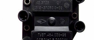
- After installing the module, look at the surface of the device. It shows numbers from 1 to 4. These are the designations of cylinder numbers.
- At the ends of the high-voltage bars there are similar numbers - from 1 to 4. They serve as a guide to determine which high-voltage wire is connected to which socket on the module.
- No experiments. Everything is connected strictly in accordance with the marks - 1 to 1, 2 to 2, and so on.
In fact, replacing the ignition module on a VAZ 2114 is quite easy. You don't need to be a professional auto mechanic to do this. Just follow the basic rules for dismantling and installation, and check the device before spending money and replacing it with a new one. It is not a fact that the culprit of problems with your car will be the module you are sinning with.
This table will allow you to check whether the wires from the ignition module to the cylinders are connected correctly.
In a car, each part is assigned certain functions. The ignition module also performs a number of important tasks, for example, when it breaks down, the engine is not able to work properly and it becomes difficult to start the car.
CHANGING THE IGNITION SYSTEM MODULE
When repairing the ignition module does not produce positive results, all that remains is to look for and install a new device. Most mechanics recommend choosing a “GM” device as a very reliable product. Its cost varies in different regions, but is close to 2000 rubles. Replacing the ignition module can be done independently, there are no special features, and no special devices are needed. For work, prepare:
- Ignition unit for replacement;
- Key to "13";
- Rags.
The work can easily be done in a garage or on level ground. Work order:
- Open the engine compartment hood and disconnect the battery terminals. It is quite enough to remove the terminal only from the negative side.
- After this, we remove the high-voltage wires from their installation locations. You need to remember where which wire was located. If you doubt your abilities, then make marks. Wires cannot be swapped. A new spare part can be damaged.
- At the next stage, carefully disconnect the connector with wires from the module. Use the key set to “13”, which unscrews the three nuts securing the device to the motor.
- When the nuts are removed, the device is removed from the engine.
Now they use rags to wipe the installation area and around it. Carefully inspect the new device and begin installing it. It is carried out in the reverse order to removal. Once again I would like to remind you of the importance of installing high-voltage wires in their places. If difficulties still arise, then take another look at the block. It shows the numbers of high-voltage wires.
Numbers - the order of arrangement of explosive wires in the module
It should be noted that on sale you can still find old-style ignition modules that do not have wire numbers marked on the high-voltage terminals. If you purchased just such a device, be careful when installing it.
VAZ models 8 and 16 valves
Despite the similarity in engine design, the ignition system of the 1.5-liter injection 16-valve engine differs from the 1.6 16-valve engine. The 1.6 liter engine uses an electronic contactless ignition system with individual coils on each spark plug. Therefore, there was no need for an ignition module. Such a system is more reliable and cheaper to operate, since if one coil fails, there is no need to replace the entire module.
The 16-valve 1.5-liter VAZ 2112 injection engine used the same non-contact ignition system as the 8-valve engine, but a different ignition module was installed. Its catalog number is 2112-3705010. The design of the module remains the same - two ignition coils (for cylinders 1-4 and 2-3) plus switch keys in a single block. The spark is supplied to the cylinders in pairs using the idle spark method. This means that sparking occurs in two cylinders simultaneously - in one on the compression stroke (working spark), in the second on the exhaust stroke (idle spark).
Design
The design of the ignition module is quite complex, since it combines technology and electrics. The device serves to create high voltage transmitted to the spark plugs. It is this supplied current that is the basis for ignition.
The operation of the module ensures fuel combustion and, accordingly, engine operation. In very simple terms, the car won’t go anywhere without the module.
For VAZ models, the use of two types of ignition modules is provided:
- Separate;
- Block.
Block ones differ in that the coils operate one per pair of spark plugs. These are the devices that are installed on the “fourteenth” model of the domestic automaker.
The coil distributes power to two candles at once, and its design includes the following elements:
- High voltage wires;
- Low voltage terminals;
- Secondary and primary winding;
- Core.
Separate modules, where the coils supply a separate circuit to each of the 4 sections, are distinguished by the output of high-voltage wires through a spring contact. Block ones are easier to check, they are easy to remove and return to their place.
It is noteworthy that with a size of 11x11x7 centimeters, this block weighs about 1.5 kilograms.
Useful video
You can find interesting information by watching the additional video below: https://www.youtube.com/watch?v=pNyBny-_HoQ
On a car with contactless ignition, everything is even easier; you don’t have to remove the wheels, but you will need an assistant. It is necessary to find the compression stroke of the fourth cylinder. To do this, insert a rubber cone into the spark plug hole and turn the ratchet. Pushing out the cone will mean that the compression stroke has been found.
Having illuminated the spark plug hole, we align the longest mark of the cover with the mark of the pulley. We set the breaker to the appropriate clock and check the operation of the system according to the fourth point described above.
Knock sensor(DD)
The knock sensor is installed on the cylinder block between cylinders 2 and 3. The functions of the sensor are to detect detonation during engine operation and transmit the received signals to the ECU. The sensor is made on the principle of a piezo element and has a simple design.
Signs of DD malfunction:
- High fuel consumption;
- Vibrations during internal combustion engine operation;
- Jerks when moving;
Frequent malfunctions of the VAZ-2114 ignition module
The following malfunctions occur in the VAZ-2114 ignition module:
- intermittency is formed at idle;
- power indicators leave much to be desired;
- the engine is not working correctly;
- in the paired operating mechanism, the cylinders are acting up (that is, the functioning of only one pair of cylinders can be heard);
- if the Check Engine light comes on.
If you suspect a faulty factory module in your car, then it's time to check the ignition module. It doesn’t hurt to make sure with your own hands that the wires are connected correctly and firmly; check that the spark plugs remain intact and are not damaged. Before you begin diagnostics and repair work, you need to stock up on protective equipment that will protect you from dangerous situations - the tool must be treated with insulating material, and gloves are required.
Signs of breakdown
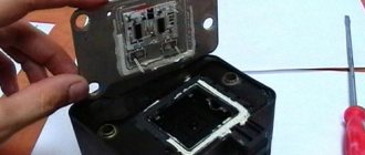
Disassembled
In fact, the symptoms of a malfunction in the VAZ 2114 ignition module are in many ways similar to the breakdown of other units. For example, you may observe the following phenomena:
- The engine is tripping;
- The car stalls at idle;
- There are problems when trying to start the car, etc.
That is, in fact, it may not be a module at all. Therefore, the only correct solution is to check the ignition module on your VAZ 2114.
How to check the malfunction of the VAZ 2114 ignition module on your own?
The easiest way to check the device without removing it is to diagnose it at the moment the power unit is tripped. When the motor begins to operate unstably, it is necessary to disconnect the connector elements from each component of the module one by one. If the connector is disconnected from a functioning device, the operation of the engine will change. Dips will appear, and the unstable operation of the unit will increase. When the non-working element of the MH is disconnected, the motor will operate in the same way.
There is another simple diagnostic method, its principle is as follows:
- You will need an assistant to check. The spark plug is removed from the seat. The high-voltage cable is disconnected from the device.
- Then the disconnected wire is connected to a spark plug, which is applied to the body of the power unit.
- The machine motor is starting, you need to make sure that a spark hits the spark plug. If it passes, a blue light will appear between the device and the surface of the power unit, its formation is accompanied by a crackling sound. If there is no spark, then the spark plugs, high-voltage cable and module must be diagnosed.
In the absence of special equipment, diagnostics of the MH can be performed using a control light indicator designed for 12 volts. One conductor from the lamp is connected to the pin of connector A, and the second is connected to ground for grounding. An assistant must start the power unit or rotate the starter mechanism. If the light flickers when performing these steps, then the device is working. Similar actions must be done with another contact.
The channel “Diary of an Auto Electrician” spoke about self-diagnosis of ignition modules, as well as other elements of the system.
Checking the ignition unit with a multimeter
Diagnostics is carried out in the following order:
- The car engine is started.
- The tester switch must be set to DC measurement mode, the limit should be up to tens of volts.
- One of the contacts of the multimeter is connected to connector D on the coil, and the other goes to ground. You can use a car body or a cylinder block as a mass. If there is power, the diagnostic tool display will show 12 volts.
- Then the tester switches to the ohmmeter operating mode, the range of values is up to tens of ohms.
- One contact of the diagnostic tool is connected to output C, and the second goes to ground. If the device is operational, the test will show a value of less than 1 Ohm.
- At the next stage, the tester must be switched to voltmeter mode. The range of values is up to tens of volts.
- One of the contacts goes to the output marked B, and the second is connected to ground.
- If the diagnostics show that the voltage is less than 0.3 volts, then the device is working. This indicates a clear signal passage from the Hall controller. Finally, you can perform a similar test, only with connector A. The results should be identical.
Direct check of secondary coils for breakdown
To diagnose secondary elements of the MH for breakdown, you will also need a tester:
- All connected conductors must be disconnected from the device connectors.
- Diagnostic equipment is set to ohmmeter mode, the range of values is up to tens of ohms.
- The contact probes of the tester must be connected in turn to the paired connectors of the module. For example, in the second and third, as well as in the first and fourth.
- If the diagnostics showed the same results, then all windings are operational. The resistance parameter should be about 5.4 kOhm. If the values obtained are higher, this indicates an internal break in the device. With lower parameters, we can conclude that there is a breakdown.
Igor Belov shared effective options for diagnosing MH in garage conditions.
We find and fix the problem
Signs of DMRV problems
So:
- The engine does not start;
- Unstable engine operation at idle;
- Engine idle speed is too high or too low;
- “Failures” during acceleration and poor vehicle dynamics;
- Fuel consumption is significantly exceeded.
Diagnostics
In addition to the above symptoms, a malfunction of the flow meter can be detected by the electronic control unit, namely its diagnostic system, which will issue a “CHECK” signal on the instrument panel. Unfortunately, without specialized diagnostic equipment with a 100% guarantee, it is impossible to identify a malfunction of the mass air flow sensor by reading error codes; you will have to contact a service station. Although, this is also controversial advice, since they will most likely offer you to identify the malfunction of the flow meter by replacing it with a known good device, but you can do this with your own hands without outside help. Let’s try to identify a flow meter breakdown in “field” conditions using four methods known to mankind. In general, we read carefully and remember. So, instructions:
The first method is the main one.
We disconnect the wire plug from the sensor and start the engine, the engine speed will rise to at least one and a half thousand per minute, and we’ll move off. If the car has acquired agility that is unusual for it, there is a malfunction of the sensor. Let me explain: the sensor is disabled, which means the ECU supplies the amount of gasoline according to the throttle position (emergency mode), without taking into account the signal from the flow meter.
When replacing the firmware in the ECU, no one will be able to say exactly what the idle speed setting is during emergency operation (method one). Therefore, this nuance is checked as follows: we slip a feeler gauge one millimeter thick under the throttle valve stop. After the speed rises, disconnect the sensor wire connector. The engine stalled - the firmware is to blame, or rather the idle speed adjustment in emergency mode.
The third method is the most accurate.
We turn the tester into DC voltage measurement mode and set the limit to two volts. We connect the probes to the yellow output wire - the plus probe and to the mass colored green wire - the minus probe, located relative to the windshield - the first and third, respectively.
Turn on the ignition, do not start the engine, take readings:
As a rule, the voltage of a working sensor is 0.996 – 1.01
Volt, but during wear it steadily increases:
- the sensor is in good condition at voltages from 1.01 to 1.02 V;
- slight wear: 1.02 – 1.03 V;
- decent mileage, will soon require replacement: 1.03 – 1.04 V;
- to be replaced at 1.04-1.05;
- It is prohibited to operate the sensor at a voltage of 1.05 Volts or higher.
Method number three
Method four, visual.
Using a curved screwdriver, remove the corrugated air duct going to the throttle assembly, and carefully inspect the internal surfaces of the air duct and sensor for the presence of condensate and oil; they should be dry and clean.
Using a ten key, unscrew the two screws and remove the sensitive element.
Checking the O-ring
As can be seen in the photo, on its front part there is a rubber sealing ring that prevents the leakage of foreign air into the intake manifold in addition to the sensor
Please note that when the integrity of the ring is destroyed, a small layer of dust forms on the sensor mesh. This is also one of the main reasons for “killing” the flow meter
In addition to the above methods, it is necessary to mention such factors as the lack of on-board power supply and unqualified maintenance (even innocent wiping of the working surfaces with a cotton swab can lead to damage to the unit). This unit is considered non-maintainable and non-repairable.
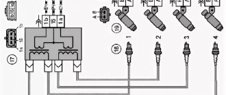
MODULE DEVICE
Design (circuit) of the VAZ 2114 ignition module The device includes two coils, the main task of which is to generate high voltage.
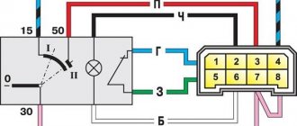
A two-channel electronic switch helps them in this. All these parts are contained in a housing made of durable plastic. The housing has a low-voltage connector for connecting the supply voltage and supplying control pulses. There are also leads for connecting high-voltage wires that are connected to the spark plugs. Electrical diagram of the VAZ 2114 starting system The figure shows an electrical diagram of the VAZ 2114 starting system. As can be seen from the figure, it consists of:
- Battery;
- Ignition switch;
- Relay that turns on the ignition;
- Hall Sensor;
- Semiconductor signal receiver from the sensor;
- Electronic switch;
- Ignition module.
- High voltage terminals.
The electrical diagram also shows the fuses of the power supply circuits of the electronic units. Let's try to look at the device and operating principle of the ignition coil. As already noted, there are two of them in the block; they are identical in design. The ignition coil circuits of one and the other are also absolutely identical. The principle of operation of the ignition coil remains the same. Both consist of cores made of electrical steel. Two windings are wound on them. One of them is low-voltage, and the second produces high-voltage voltage to ignite the working mixture.
The ignition coil connection circuit is made in such a way that one end of the low-voltage winding is connected to the supply voltage, and the other end of these windings is connected to a transistor generator. Each coil has its own transistor. The high-voltage leads are connected directly to the spark plugs; each winding supplies energy to two spark plugs. One of them outputs pulses to cylinders 1 and 4, and the second to cylinders 2 and 3.
The wires on the ignition module are arranged as follows. Contacts A and B receive control pulses from the electronic switch, pin D receives power from the machine’s on-board network. The terminal marked with the letter C is connected to the vehicle ground.
How to replace it yourself
Preparatory stage:
- Open-end wrench set to “19”;
- Rags;
- Additional lighting as needed;
- New "measuring device".
Replacement algorithm:
- We install the VAZ 2114 in the perimeter of the repair area;
- We turn off the engine, open the hood;
- We provide priority safety measures: block the rear row of wheels with wheel chocks, squeeze the parking brake;
- Remove the terminals from the DTOZH, unscrew the sensor with a key;
- We replace the device with a new one, screw it in, and put on the power terminals again.
We turn the key in the ignition, activate it, and check the functionality of the equipment. Add the missing amount of antifreeze as needed.
Selected aspects of technical operation
Often the reason for many calls to the service station is not so much malfunctions in the high-voltage wires, but rather the incorrect operation of the Kalina ignition module. To carry out diagnostics, you can go to a service center or pick up the tools yourself. One of these is a multimeter used to measure the actual resistance level on the 8-cell pins. engine. To obtain correct measurement results, it is necessary to carry out 2 times.
The ignition system can be damaged in any part of the circuit, so monitoring must be careful. It all starts with checking that the winding is properly connected to ground. It is necessary to carefully insert the contacts, focusing on the indicators of the device. Then one of the contact terminals of the device is connected to the central contact of the spark plug coil. In this case, the second contact is attached to ground.
Possible reasons for failure of the ignition module
Generally speaking, the ignition module is a completely reliable device, and its breakdowns are quite rare. At the same time, the weakest point inside the module is the primary windings of each of its coils - it is on these windings that high voltage is generated, so sometimes breakdowns, breaks or melting of the turns can occur there.
The main reasons causing overloads and improper operation of coils, leading to their breakdowns, are:
- use of unsuitable, faulty or dirty spark plugs;
- frequent spark checks;
- operation of the module with disconnected or damaged high voltage wires;
- high vibration of the fixed module, causing damage to the factory soldering inside it;
- poor contact inside the low-voltage wire connectors.
Ignition module failure
In addition, a fairly common cause is the usual ingress of water into the module (which often happens when the car is operated in a damp environment or after washing).
Repair or replacement?
As the practice and experience of car repair technicians shows, most often it is not possible to repair this device. The module can only be replaced. If you follow the principle, it is possible to carry out repairs, but it will take a lot of time, effort and even money.
Installing the module
The best option is to purchase a new device. It costs around 2-4 thousand rubles. It all depends on the manufacturer and condition. You can buy a brand new one, although many people prefer used devices. Here the choice is yours.
List of devices
Sensors are needed to report on the performance of systems, signal the level of cooling liquids and oil, and prevent or anticipate emergency situations.
These small devices, despite their size, play an incredible role in the performance of the machine. Therefore, it will not be superfluous to know which sensors are on your car.
Let us list the main ones present in the VAZ 2114 systems. We include sensors in this list:
Coolant temperature;
Coolant level in the expansion tank;
Mass air flow rate indicator;
Engine idling;
Brake fluid level in the system;
Camshaft position (it is called a phase sensor);
Outside air temperature;
Uneven road surface.
This list is very, very extensive. But even this, the owners of the VAZ 2114 do not want to stop, which is why they are introducing several more different sensors into the system:
- Light devices;
- Reverse;
- A device that signals open doors;
- Brake pad wear indicator, etc.
How to check the ignition coil of a VAZ
If the ignition coil is faulty, the engine will not start. A characteristic sign of a faulty coil is its increased temperature when the ignition is turned off. This is easy to determine by touch.
Signs of a faulty ignition module may include the following:
- hesitant engine starting or failure to start;
- failures during sudden changes in speed;
- high fuel consumption;
- two cylinders do not work, the engine is feverish;
- lack of dynamics;
- a sharp drop in power;
- drop in power and thrust after warming up.
These symptoms may not only be caused by the ignition module. To determine the malfunction, it is enough to spend a few minutes diagnosing spark plugs, high-voltage wires and caps. This will eliminate the remaining elements of the ignition system and make sure that it is the ignition module that is faulty.
Checking the ignition coil is performed in one of 2 ways. The simplest one is to remove the central wire from the breaker-distributor, bring it to the motor housing and turn it with the starter, and a running spark should appear. After this, we check the energy supply to a separate spark plug, for which we unscrew the working spark plug, bring its contact to ground and attempt to start the engine. In this case, the spark should come from the wire to ground. If it is absent, the reason will be a malfunction of a system element such as the ignition coil.
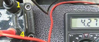
To check the module in the second way, we only need a multimeter, then follow the step-by-step instructions:
- We check the power supply and the presence of pulses supplied from the ECU. We check the power between the central terminal (15) of the wire block connected to the module and the engine ground. When the ignition is on, the voltage should not be less than 12 V. Otherwise, either the battery is dead or the ECU does not work.
- We check the pulses from the ECU on the wiring block. We install one tester probe on connector 15, the second on the far right, then on the far left. The assistant cranks the engine with the starter, and at this time we record short-term voltage surges with a tester. If there are no impulses from the ECU, it is he who is to blame.
- We check the resistance on the secondary windings of the coils. We put the tester in resistance measurement mode and measure it at the high-voltage terminals of the module cover. Between pins 1 and 4 and pins 2-3, the resistance should be 5.4 kOhm. Otherwise, the module must be replaced.
- We check the resistance of the primary windings between contacts 15 and the rightmost, then the leftmost terminals. Nominal - 0.5 Ohm. Deviation is not allowed.
- Check the module for a short circuit. In ohmmeter mode, install one multimeter probe on the central terminal, the second on the metal body. There shouldn't be any resistance. If the device detects at least some resistance (other than unity or infinity), the module must be replaced.
Useful: VAZ cooling fan connection diagram
HOW TO CHECK THE SYSTEM FOR OPERATION
In any case, the check begins with the candles. To do this, they need to be removed from their nests. This is also easy to do. Remove the tips of the high-voltage wires from them and, using a wrench for turning out the spark plugs, remove them from their places.
Next comes their inspection, cleaning and testing. They should have a working brown color, with no soot or soot. If their presence is observed, then there may be wear on the pistons and rings. In any case, the spark plugs are cleaned, checked and, if necessary, the gap between the electrodes is adjusted. After this you can check their functionality
There are special probes for these purposes. “Craftsmen” manage to make such products themselves from a piezo lighter. If nothing like this is available, then check it on the engine. It’s good if there is a car nearby with a known good starting system. This will make it possible to make an accurate diagnosis for candles. If they are in good condition, the search continues further.
Many publications recommend checking for the presence of high voltage voltage at the terminals of the device. Doing this in a garage is problematic due to the lack of a special measuring device. A conventional tester is used here, since it cannot measure several tens of kilovolts of high voltage. If you have experience as a radio amateur, you can assemble a voltage divider.
Checking for the presence of high voltage is dangerous due to a possible sensitive electric shock, so we will touch on other methods. Let's talk about how you can determine ignition coil malfunctions and check this system:
- The simplest method is to replace the unit with a working device. It is not always possible, since not all drivers carry this device with them in reserve;
- They also advise, which has been tested many times, to move the device or knock on it while the motor is running. If changes are noticeable, they indicate poor contact inside the device. Sometimes it's fixable;
- Check with a tester or multimeter in resistance measurement mode. The resistance of the paired terminals of the coils, 1 and 4, as well as 2 and 3, is measured. It should be identical for both windings and equal to approximately 5.4 kOhm.
Operation in various conditions
Many inexperienced drivers, not understanding the essence of the breakdown, decide that an expensive replacement of the ignition switch or the wiring as a whole is necessary. Experienced drivers advise not to rush to conclusions. If, due to various circumstances, the ignition coil fails, the corresponding indicator lights up on the dashboard. The first thing the driver should do in such a situation is to drive the car into the garage and open the hood.
Often spark plugs fail due to a power surge or short circuit. As a result, the spark does not travel properly throughout the system. A number of other circumstances can cause a similar problem:
- the car was damaged in an accident;
- replacement of spark plugs may be required after lightning strikes the car;
- poor-quality previous repairs;
- use of non-original spare parts;
- failure to comply with technical inspection deadlines at the service center.
Regardless of the reason, the ignition circuit needs a full analysis. Often the problem is complex. That is why, if the driver does not have enough technical experience, the first decision that comes to mind should not be accepted as the only correct one.
Air sensor VAZ-2114
Modern environmental requirements for internal combustion engines are increased. That is why, in all modes of its operation, the established ratio of air to fuel in the air-fuel mixture must be maintained.
Only if these conditions are met will the catalytic converter completely remove harmful substances in the exhaust gases.
To maintain the stoichiometric ratio of the various components present in the fuel-air mixture, reliably accurate information on the amount of air consumed is required.
The air flow sensor installed on the VAZ-2114 is designed to collect air flow data. The measure of intake air flow can be calculated both in volume and in mass.
Today there are two types of air flow sensor: thermal and mechanical.
With the mechanical method, the incoming air is measured, which is proportional to the movement of the damper. The basis of the thermal method is to measure the mass of incoming air, which directly depends on the temperature of the sensitive element for a given period of time. The car's air flow sensor is installed between the throttle valve and the air filter in the intake system.
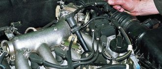
How to remove the ignition module?
- Using the “10” key, remove the negative terminal from the battery.
- On the 1.6 engine, remove the plastic decorative trim on the engine by unscrewing the oil filler cap and pulling out the plastic trim. On a 1.5 engine there is no decorative trim.
- We remove the wire block from the module.
- We remove the high-voltage wires from the ignition module.
- Using a key set to “13”, unscrew the 2 fastenings to the engine crankcase.
- Using the key “17” we loosen the last fastening of the module.
- We take out the module.
- Using a hex screwdriver, unscrew the module itself from its holder.
Then you can begin repairing the module, draining the coolant, replacing the thermostat, removing the box, etc.
Purpose and principle of operation
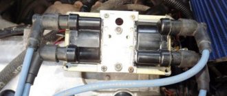
The ignition module of a VAZ-2114 car with an injection 8-valve power unit is located directly opposite the engine block on the spark plug side. This arrangement is most effective for supplying high-voltage wires to the spark plugs. The device is mounted on the wall of the engine compartment. This position was not chosen by chance. This way the MH interacts less with vibrating parts of the car.
The device that comes with the described car model is of the block type. One housing contains 2 inductors and 2 discharge voltage regulators. The device operates according to the following principle:
- A pulse signal passes from the crankshaft position controller to the on-board computer.
- The signal is confirmed by a pulse signal from the Hall sensor of the ignition system.
- Both signals are calculated in the on-board computer and transmitted as current to the module.
- The module converts 12 volt voltage into high current.
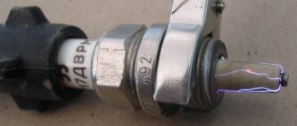
- From the coil, the voltage is supplied to the spark gap, which forms a pulse voltage.
- The voltage passes through the high voltage wire of cylinders 1 and 4 to the spark plug.
- The spark plug is discharged by a spark, igniting the fuel in the cylinder.
- During the discharge, spark plugs 2–3 also receive voltage, but its power is adjusted by the spark gap.
All components are made of high-strength plastic with an aluminum plate for mounting to the engine. Additionally, both coils are filled with insulating solution. On the body of the device there are only 4 contact sockets for high-voltage wires and an electrical power socket.
Subject to all operating rules, the ignition module is a very reliable electronic device, but it is quite fragile. If the electrical circuit has a number of damages and is often subject to short circuits, then the coils or arresters fail.
Any malfunction of the MH leads to interruptions in engine operation. The following will describe the main symptoms of a malfunction of this device.