VAZ 2114 ignition module and its purpose
The VAZ 2114 8 valve ignition module is a special device, the purpose of which is to convert electrical energy coming from the generator into a current with a very high voltage. In addition, the module also plays the function of a distribution device that diverts increased voltage to the spark plugs.
By its design, it is a paired system, including two pairs of windings, as well as a commutator. The purpose of the latter is to alternately switch the incoming low-voltage electricity from one coil to another.
The ignition module, unlike ignition coils (which were used in earlier periods of the automotive industry), has not two, but four pairs of terminals, which are used to connect high-voltage wires, which, in turn, go to the spark plugs.
Pulses in the module, in this case, appear alternately in pairs - first on connectors 1 and 4, and then on 2 and 3. The ignition module itself is controlled using a special electronic unit.
Ignition module block
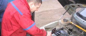
Examination
It is a mistake to assume that damage to high-voltage wires does not in any way affect the condition of the module itself. Many people think of simply replacing high-voltage elements, but in reality they will still have to change the module.
This is explained by the fact that damaged or defective wires direct the wrong current, the configuration of which does not correspond to the necessary parameters. As a result, the spark hits inaccurately or ineffectively, causing the module to burn out and become unusable.
Article on the topic: Replacing the CV joint on a VAZ 2110 with your own hands
In general, the best option for checking the ignition module on a VAZ 2114 is to use an oscilloscope . But, firstly, not every driver has it, and secondly, few people can use them. Therefore, we will carry out the check using improvised means:
- 12-volt light bulb;
- Tester (available for little money at any auto parts store).
Let's start with preliminary manipulations with the accompanying elements of the ignition module.
- Check the wiring harness. It is disconnected and the voltage indicator is checked.
- To do this, fix the tester on contact A, and connect the other terminal to engine ground.
- In normal condition, the voltage reading will be 12V.
- If there is no voltage, most likely the fuse has blown.
- If everything is fine, transfer the terminals of your tester to contacts A and B, start the car. In this case, the starter should turn and the 12-volt light should blink.
- In the absence of these phenomena, we can talk about the presence of a break in circuit A of the contacts.
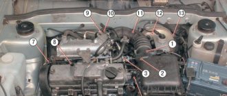
Next we go to the ignition module itself.
There are several ways to check the condition of your unit. Therefore, let's look at each of them.
- Set the tester to ohmmeter mode. Use it to measure the resistance on the high-voltage lines going to cylinders 1 and 4, and then, by analogy, to the wiring of cylinders 2 and 3. In normal condition, the device will give you readings from 5.2 to 5.5 ohms.
- Give the device a gentle tug. Thus, you will shake the wiring block and the module. Moreover, this must be done in the operating mode of the power unit. If the device works without obstruction when loosened, everything is fine, you are lucky. If not, you will again have to study the condition of the wiring.
Third way
The third method is considered the simplest, since it involves replacing your device with a similar one that works exactly. But to do this, you have to find a full-fledged twin. We are talking about an ignition module from a car similar to yours in terms of year of manufacture and power unit used. It’s just that 1.5-liter engines have modules, and 1.6-liter engines have coils.
But to replace a module with a module, you will have to first dismantle yours. This is done as follows:
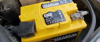
- Remove the negative terminal from the battery, which will allow you to turn off the power to the car;
- Disconnect four high voltages from the ignition module;
- Disconnect the wire block. To do this, you need to release the special clamp that holds the block on the module;
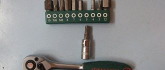
- Next, unscrew the three nuts. With their help, the module is held on the bracket;
- There are three long pins on the bracket, from which the module can simply be pulled off.
Article on the topic: Installing heated seats in a VAZ 2110
Having dismantled your module, you can put another unit in its place, thereby verifying the functionality of that one and the malfunction of yours.
Possible reasons for failure of the ignition module
Generally speaking, the ignition module is a completely reliable device, and its breakdowns are quite rare. At the same time, the weakest point inside the module is the primary windings of each of its coils - it is on these windings that high voltage is generated, so sometimes breakdowns, breaks or melting of the turns can occur there.
The main reasons causing overloads and improper operation of coils, leading to their breakdowns, are:
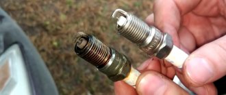
- use of unsuitable, faulty or dirty spark plugs;
- frequent spark checks;
- operation of the module with disconnected or damaged high voltage wires;
- high vibration of the fixed module, causing damage to the factory soldering inside it;
- poor contact inside the low-voltage wire connectors.
Ignition module failure
In addition, a fairly common cause is the usual ingress of water into the module (which often happens when the car is operated in a damp environment or after washing).
Ignition module 2114 - causes of malfunction
The main point that you should pay attention to when the ignition module breaks down is unstable floating engine speed, jerking when driving, indicating that the engine is running rough, difficult starting of the engine or it refuses to start at all, the “Check Engine” light on the dashboard comes on, the description of which We have done this more than once on the website provaz2114.ru, these are the main signs of failure of the ignition module.
Causes of malfunction
Carrying out diagnostics yourself is quite difficult, because the ignition module of the VAZ 2114 8 valves includes several devices, despite the fact that it is made of one plastic case. It is simply impossible to check all devices separately without special equipment. But this does not stop experienced car enthusiasts. At least, if not repaired, then it is quite possible to detect signs of a malfunction in the ignition module on a VAZ 2114 using improvised means.
Checking contacts
- Firstly, before you start repairing the most important part in the ignition system of your iron horse, you need to find out what exactly is not working there.
- Immediately check the quality of the contacts of all blocks of the low voltage circuit, and also look at the contacts of each high voltage wire.
Checking the power supply to the ignition module
How to check the ignition module of a VAZ 2114 injector 8 valves?
- To do this, we determine whether there is power supply to it.
- To do this, you need to take the connector in the block and find the contact marked with the letter A.
- To measure the module's power supply, take a micromultimeter, select the AC measurement mode up to 20 V, apply the negative probe to the engine ground and turn on the car's ignition.
- We apply another probe to contact A on the block.
- If the electrical equipment is fully operational, the micromultimeter will show 12 V, this means that power is supplied to the module, we look further for the cause of the malfunction.
Checking the connector contacts
Using this test, we were able to verify that power was supplied to the ignition module. This means you need to check each contact separately.
- Turn on the ignition, take the test lamp and connect it to two contacts at once: contact A and contact B.
- The control indicator can be made from a 12-volt low-power lamp with pre-soldered contact wires, or you can use a 12-volt automotive test probe with a voltage indication.
How to check the ignition module with a lamp on a VAZ 2114?
- We apply the contacts of the test lamp or probe to outputs A and B, then turn the engine starter.
- If the light flashes, the ignition module breaks the contacts as if it were a contact breaker. This means that contacts A and B are in perfect order.
- If the light never blinks when the starter starts, the ignition module is faulty.
Signs of coil malfunction
Before starting an instrument test, you can try to determine whether the ignition coil of the VAZ 2114 8-valve injector is working by indirect signs (in some cases they are enough to verify a breakdown).
These include:
- instability (intermittency) of idle speed;
- the engine gains speed with great difficulty;
- “triple” when the engine is running;
- The speed gain while driving occurs in strong jerks.
Connecting the ignition unit
If these signs are present (especially if there are several of them), you can either immediately replace the faulty module, or finally establish the fact of its malfunction using instrumental analysis.
How to check the ignition coil with a tester on a VAZ 2106, as well as VAZ 2109 and VAZ 2110 (carburetor)
On old VAZs it is not difficult to find a coil. It is located in a freely accessible area, under the hood. To check, you will need a regular multitester, which can be purchased for a small amount in many stores.
Video tutorial on measuring ignition coil resistance
The procedure is as follows:
- Disconnect the negative voltage on the battery. Disconnect the ignition coil wires, loosen the brackets. Clean the reel body. If obvious damage, cracks, etc. were discovered, it is better to immediately replace the device with a new one, since such a coil cannot be used.
- On the tester, turn on the ohmmeter mode. To check the “primary”, install probes or clamps on the side terminals located on the coil body. The tester display will show about 3.07-3.5 Ohm (original coil 2106 for a contact ignition system) or 0.45 ± 0.05 Ohm (coil 27.3705 for a contactless ignition system). For VAZ 2108, 2109 and 2110 - 0.43±0.04 (coil 3122.3705) and 0.42±0.05 Ohm (coil 8352.12). If the “primary” is broken or burned out, the resistance indicators will most likely tend to infinity.
- "Secondary" requires a similar check. But now the first probe goes to the side terminal, and the second to the central terminal. In addition, the indicators will be calculated in thousands of ohms. So, in accordance with the factory figures for the VAZ 2106 it should be 5400-9200 Ohms, for 2109 and 2110 - 0.40 kOhm (coil 3122.3705) or 1.00 kOhm (coil 8352.12).
- Also check the insulation resistance to ground. To do this, install one probe on the coil body, the second on each of the terminals in turn. The tester should show at least 50 mOhm.
The ignition coil cannot be repaired
Strong deviations from the normal range are a reason to replace the coil with a new one. It should be noted that this element of the ignition system cannot be repaired.
'center', 'clear' => ", 'margin_top' => ", 'margin_bottom' => ", 'padding_top' => ", 'padding_bottom' => "), array(), array()) —>
How to check the malfunction of the VAZ 2114 ignition module on your own?
In order to start checking, you will need a measuring device - a tester. Before starting the measurement, the wire blocks are removed from the connectors. Each block has its own slot (A, B, C, D).
Checking the VAZ 2114 ignition module with a multimeter:
- turn on the car engine;
- set the multimeter switch to measure direct current up to tens of volts;
- one of the probes of the device is connected to connector D, the second to ground. If there is power, the screen will show 12 volts;
- switch the multimeter to ohmmeter mode up to tens of ohms;
- one probe is connected to connector C, the other to ground. If everything is in order, the device will show less than 1 Ohm;
- switch the multimeter to voltmeter mode up to tens of volts;
- one probe is connected to connector B, the other to ground. If a voltage of at least 0.3 Volts is displayed, then everything is fine (a clear pulse comes from the Hall sensor);
- The last measurement with connector A is carried out exactly as in the previous case.
Checking the ignition unit with a multimeter
Before you start testing the ignition module, you should carefully check the quality and reliability of the contact of all wires approaching and departing from it - perhaps this is the only reason.
Another testing method is to directly check the secondary coils for breakdown.
It is performed according to the following scheme:
- all wires are removed from the connectors;
- the multimeter is set to ohmmeter mode up to tens of kOhms;
- the probes are alternately installed in paired connectors (1 and 4, 2 and 3);
- if the windings are in good condition, both measurement results will be the same (on average, they should be equal to 5.4 kOhm). If the resistance turns out to be much higher, then there is an internal break in the turns; if it is much lower, there is a breakdown.
Checking high voltage wires
Also, there is another, easiest way to check the ignition coil of a VAZ 2114 - simply replace it with a new one, completely similar. If after replacement the car began to work properly, then the reason was definitely in the module.
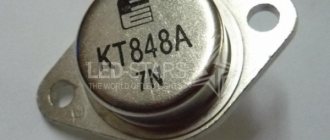
Design and principle of operation of the ignition module
Some old-school motorists call the modules double-spark coils, which makes sense. After all, the coil is the predecessor of the ignition module in the technical evolutionary chain. The module is a paired design consisting of two pairs of windings (primary and secondary) and a switch that alternately switches low-voltage current from one coil to another. In some models of double-spark coils, the commutator is structurally located outside the block.
The operation of the module is controlled from an electronic unit that collects and analyzes information from various working components of the engine. The block, unlike the classic coil, has 4 sockets for connecting high voltage wires going to the spark plugs. The pulse occurs in pairs, first at terminals 1 and 4, then 2 and 3. That is, each of the built-in coils is responsible for the operation of two cylinders. A spark occurs simultaneously, as a pair.
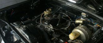
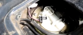
This is what one of the ignition module models looks like. The connector for connecting incoming wires is visible at the top.
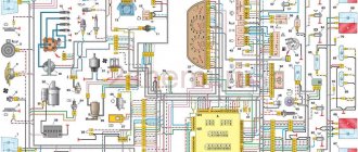
At the input, the ignition module has a connector with four terminals. Usually most models have markings opposite them. Pulses from the Hall sensor alternately arrive at contacts A and B, serving as a signal to switch the commutator from one primary winding to another. C and D – ground and power supply (12 V), respectively.
Possible causes of failure
The weak point of the ignition coils and modules is the secondary winding, which generates a high voltage pulse. A coil break or breakdown may occur in it. The following factors lead to this phenomenon:
- use of low-quality or unsuitable candles;
- operation with non-functioning high voltage wires;
- frequent attempts to check the spark.
The high-voltage pulse arising in the secondary winding must be realized (spent). If this does not happen (if the integrity of a high voltage wire is broken, for example), a high-energy electrical pulse seeks an outlet. He will find it, with a high degree of probability, in the thin secondary winding.
Often, a module malfunction occurs when the integrity of poor-quality factory soldering of wires going to the switch elements is violated. This happens from vibration. Also, the cause of non-working coils can be a banal contact failure in the incoming connector. Another factor leading to a malfunction of the ignition unit is often moisture that gets on the device during washing or driving in unusual conditions.
Symptoms of a problem
It is extremely rare for two built-in coils to fail at once, so it is more likely to be possible to start the engine with a faulty unit. However, even an inexperienced driver will immediately suspect something is wrong. The malfunction will appear as follows:
- unstable (floating) idle speed;
- the engine has difficulty picking up speed;
- characteristic sound of the engine (triple);
- jerking when accelerating (while moving).
Operating a car with such a breakdown is possible (you can drive to a garage or car service station), but it is not advisable unless absolutely necessary.
Similar signs of unstable engine operation are possible with a number of other ignition or fuel supply faults. To differentiate possible breakdowns, the performance of the ignition unit should be determined. It would be useful to check the contacts of the wires coming to the device, as well as their integrity.
Checking module power
Before testing the performance of the coils, you should make sure that a possible breakdown is not caused by a loss of power to the device. First, you need to try to simply restore contact by moving it several times or disconnecting/connecting the block of wires included in the connector. If such manipulation does not lead to improved engine performance, a tester (multimeter) is used to determine the quality of incoming pulses.
The block of wires is removed from the connector. On the block, each terminal (A, B, C, D) has a corresponding socket. Testing with the engine running is done as follows.
- The first contact of the tester is in socket D, the second is to ground. The multimeter switch position is 20 volts. If there is power, the tester shows 12 volts. The first contact is in socket C, the second is ground. Switch on ohmmeter (20 Ohm). IN
- normally shows less than 1 ohm, that is, the mass is normal.
- The first contact is in socket B, the second is ground. 20 volt switch. The norm is not less than 0.3 volts. If this is so, it means that a normal pulse is coming from the Hall sensor to position B.
- Contact A is checked similarly to the previous one.
If such a check shows the norm, you need to test the module. If not, look for the cause in the electrical circuit to the coil.
Methods for diagnosing device performance
The simplest method that will help determine the performance of the coil is to replace it with a similar working device. This is possible if there is somewhere to get it. Please note that the module must match the parameters of the device under test. If the engine with a working coil works as before the breakdown, the ignition module is definitely faulty.
The main testing method involves using a multimeter. It consists in determining the resistance of the secondary windings of the coils built into the ignition module. The method is simple and does not require additional skills. The device does not need to be removed for testing. The check is done with the engine turned off.
This is how you check the resistance of the secondary winding with a multimeter
- High-voltage wires are removed from the module sockets.
- The tester switch is set to the 20 kOhm position.
- The multimeter rods are placed in turn in the recesses of the corresponding contact pairs (1 and 4, 2 and 3).
- With an intact secondary winding, the performance in both cases is the same. Normally, the resistance should be about 5.4 kOhm (in some models the indicators differ, which needs to be clarified). If the resistance is much greater, then there is a winding break. The resistance is much lower - a breakdown. The coil is faulty and cannot be repaired.
Video: How to check the secondary winding with a multimeter
When is there an option to repair?
If during testing both secondary windings show integrity and serviceability, the reason for the inoperability of the coils may be a break in the soldering of the switch wires. Such damage is detected when the rear cover of the module is removed. If you have a soldering iron and know how to use it, you can restore the integrity of damaged contacts, while at the same time strengthening the rest. This, unfortunately, is the only failure of the ignition module that can be repaired.
Testing the ignition module can be done using simple do-it-yourself instruments. Based on our advice, you will be able to fully check both the module itself and other elements of the mechanism that may be the cause of the breakdown. We wish you success in this matter!
Ignition module repair
Due to the fact that the design of the module consists of a pair of coils, its maintainability is extremely low. So, if there is a breakdown, breakage, fusion of the turns, as well as other damage inside the coils, then nothing can be done here - all that remains is to replace the failed module with a new, similar one. The only case when you can try to solve the problem without purchasing a new device is if the solder is damaged.
This can be found out by testing (using the methods described above). If the serviceability of the secondary windings has been established, you can try to open the module cover and visually determine the damage to the soldering.
If such damage cannot be determined, then you can simply try to thoroughly solder all the contacts inside, then install the module in place and start the engine - if this was the cause of the breakdown, then the car will start working properly again.