Colored wiring diagrams for the VAZ 2110 (injector and carburetor engine) are provided with a description of all elements for various modifications. The information is intended for self-repair of the car. Electrical circuits are divided into several blocks for ease of viewing via a computer or smartphone; there are also circuits in the form of a single picture with a description of the elements - for printing on a printer in one sheet.
There are two types of electrical wiring for the VAZ-2110: carburetor and injector. There are slight differences, but the basic principles of operation and wiring are the same. Depending on the location, the wiring differs into: under the hood and in the cabin. All electrical equipment of the car is connected using wires of a certain color. Each element has its own wiring harness through the blocks and fuses.
VAZ 2110 - modifications
VAZ-21100 . The base model which was produced from 1996 to 2000. The car was equipped with an 8-valve carburetor VAZ-21083 engine with a displacement of 1.5 liters and a power of 69 horsepower.
VAZ-21101 . This modification has been produced since 2004, equipped with an 8-valve gasoline injection engine with a displacement of 1.6 liters.
VAZ-21102. Like the previous modification with an 8-valve injection engine, but with a volume of 1.5 liters.
VAZ-21103 . Modification of the “tens” with a 16-valve injection engine with a working volume of 1.5 liters.
VAZ-21103M . A restyled modification of the VAZ-21103, equipped with a 16-valve petrol injection engine with a displacement of 1.5 liters and a power of 92 horsepower. Produced since 2002.
VAZ-21104 . The modification is equipped with a 16-valve petrol injection engine with a working volume of 1.6 liters.
VAZ-21104M . A restyled modification of the VAZ-21104, equipped with a 16-valve petrol injection engine with a displacement of 1.6 liters. Produced since 2004.
VAZ-21106 GTI . The engine of the VAZ-21106 GTI is the most powerful and expensive modification that has been produced since 2000. The car was equipped with a 2-liter 16-valve Opel C20XE gasoline engine with a capacity of 150 horsepower. The car was fitted with a body kit with swollen arches, and the track was widened by 76 millimeters. It was equipped with R15 wheels with low-profile tires.
VAZ-21106 Coupe . Coupe VAZ-21106 in a coupe body. A distinctive feature of the car was the presence of only two doors, which were lengthened by 250 millimeters, while the body was shortened by 170 millimeters. The engine was installed the same as in the previous VAZ-21106 GTI model.
VAZ 21106 WTCC . A sports modification of the 106 model, it participated in the 2008 FIA WTCC international championship.
VAZ 21107 . Modification of a car for rally competitions. It was equipped with a welded safety cage and a different suspension design.
VAZ 21108 "Premier" . A modification with a body lengthened by 170 millimeters in the rear door area, which provided more convenient entry and exit of passengers. It was equipped with a 1.5-liter injection 16-valve engine.
VAZ 21109 “Consul” . 4-seater luxury limousine based on the VAZ-2110 car. In addition to the length of the body, the dimensions of the rear door were also increased, for more convenient entry and exit of passengers. Equipped with a 1.5 liter engine and R14 or R15 wheels. Overall dimensions: length - 4950 mm, width - 1700 mm, height - 1440 mm. Fuel consumption in the urban cycle is 9.5 liters per 100 kilometers.
VAZ 2110-91 . Modification of the VAZ-2110 with a 1308 cm3 rotary piston engine. The car could reach speeds of up to 240 km/h, and acceleration from 0 to 100 km/h took 6 seconds.
A car with a 16-valve injection engine in the Gran Lux configuration includes:
- Electric windows;
- Door locking;
- Trunk lock lock;
- Velvet seat upholstery;
- Immobilizer;
- Heated front seats;
- Ventilated 14-inch brake discs;
- Rear spoiler with additional brake light;
- Fog lights.
Replacing fuses
If after replacing the bulbs the lighting still does not work, you should check the fuses. The mounting block is located on the left side of the steering wheel.
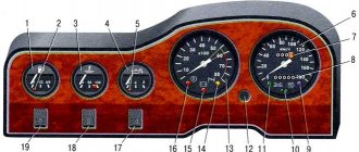
Fuse layout
Fuse F2 is responsible for low beam lighting in the left headlight unit, and F12 in the right one. It must be said that a fuse malfunction cannot always be detected visually. Therefore, it is better to install new fuses.
Wiring diagram for VAZ 2110 carburetor
In the instrument panel wiring harness, the second ends of the wires of white, black, orange, white with a red stripe and yellow with a blue stripe are connected to each other at the same points. The bends of the wires at the points of entry into the harness indicate the direction of their laying in the bundle.
See the complete diagram in one file below (click to enlarge):
1 – headlight 37 – instrument cluster 2 – front brake pad wear sensor 38 – rear fog light switch 3 – fan motor switch 39 – fog light indicator lamp 4 – engine cooling system fan electric motor 40 – rear window heating indicator lamp 5 – sound signal 41 – clock 6 – generator 42 – rear window heating switch 7 – oil level sensor 43 – steering column switch 8 – carburetor solenoid valve control unit 44 – block for switching wires when installing headlights of another type 9 – heater controller 45 – switch instrument lighting 10 – recirculation valve switch 46 – ignition switch 11 – illumination lamp for heater control levers 47 – connectors for connecting the headlight cleaner wiring harness 12 – switch 48 – socket for a portable lamp 13 – carburetor limit switch 49 – directional light 14 – control sensor oil pressure lamps 50 – brake light switch 15 – spark plugs 51 – interior lamp 16 – carburetor solenoid valve 52 – on-board control system unit 17 – coolant temperature indicator sensor 53 – fuel level indicator sensor 18 – ignition distributor 54 – hazard warning switch 19 – ignition coil 55 – driver’s seat belt sensor 20 – starter 56 – cigarette lighter 21 – heater fan motor 57 – ashtray backlight lamp 22 – additional resistor for heater motor 58 – glove compartment light switch 23 – speed sensor 59 – connector for on-board computer 24 – reverse light switch 60 – glove box lighting lamp 25 – micromotor gearbox for heater flap drive 61 – side turn signal 26 – recirculation valve 62 – switch in the front door pillar 27 – brake fluid level sensor 63 – switch in the rear door pillar 28 – pads for connecting the rear window washer motor 64 – parking brake warning lamp switch 29 – battery 65 – trunk light 30 – windshield washer motor 66 – interior air temperature sensor 31 – washer fluid level sensor 67 – external rear light 32 – level sensor coolant 68 – internal rear light 33 – windshield wiper motor 69 – license plate light 34 – mounting block 70 – block for connecting the rear window heating element 35 – blocks for connecting the warning light harness 71 – block for connecting an additional brake signal 36 – outdoor light switch
Connection diagram 2110
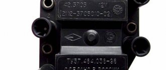
Wiring diagram for connecting the starter VAZ 2110 model 57.3708 or 2110-3708010-02
| Position number on the starter connection diagram 57.3708 or 2110-3708010-02 | Explanation of position |
| 1 | electricity storage |
| 2 | generator |
| 3 | starter VAZ 2110 model 57.3708 or 2110-3708010-02 |
| 4 | ignition switch |
Wiring diagram for windshield wiper and washer
| Position number on the diagram | Explanation of position |
| 1 | windshield cleaner |
| 2 | windshield washer |
| 3 | windshield wiper and washer switch |
| 4 | mounting block VAZ 2110 |
| 5 | egnition lock |
| K2 | glass cleaner switch |
| K6 | Additional relyushka |
| A | Conventional numbering of plugs in the wiper motor blocks |
| IN | to sources of electricity |
Wiring diagram for connecting external lighting VAZ 2110
| Position number on the diagram | Explanation of the position on the external lighting diagram of the VAZ 2110 |
| 1 | lamp dimensions in the Faroah block |
| 2 | mounting block |
| 3 | size switch |
| 4 | ignition switch |
| 5 | Dimensions control on the dashboard |
| 6 | tail light bulbs |
| 7 | brake lamps |
| 8 | room lighting lamps |
| 9 | instrument lighting switch |
| 10 | brake lamp switch |
| 11 | VAZ 2110 on-board control system unit |
| K1 | relay for monitoring the health of lamps (contact jumpers are shown inside the relay, which must be installed in the absence of a relay) |
| A | to power supplies |
| IN | to instrument lighting lamps |
Electrical circuit for connecting an audio signal
| Position number on the diagram | Explanation of position |
| 1 | signal |
| 2 | signal switch |
| 3 | fuse box VAZ 2110 |
| A | terminal block for engine cooling fan |
| IN | to energy sources |
Diagram of VAZ 2110 injector 8 valves
1 – headlight 2 – front brake pad wear sensors 3 – horn 4 – cooling system fan 5 – reverse light switch 6 – battery 7 – generator 8 – oil pressure warning lamp sensor 9 – oil level sensor 10 – spark plugs 11 – injectors 12 – idle speed control 13 – electronic control unit blocks 14 – throttle position sensor 15 – crankshaft position sensor 16 – ignition module 17 – coolant temperature indicator sensor (for instrument cluster) 18 – starter 19 – diagnostic block 20 – coolant temperature sensor (for the engine management system) 21 – speed sensor 22 – fuel pump switch relay 23, 35, 39 – fuses 24 – electric fuel pump 25 – micromotor gearbox for heater damper drive 26 – recirculation valve 27 – heater fan 28 – windshield washer pump windows 29 – washer fluid level sensor 30 – brake fluid level sensor 31 – coolant level sensor 32 – windshield wiper gear motor
33 – additional heater fan resistor 34 – injection system power supply relay 36 – canister purge valve 37 – mass air flow sensor 38 – cooling system fan activation relay 40 – external lighting switch 41 – knock sensor VAZ-2110 injector 42 – oxygen concentration sensor ( heated lambda probe) 42* – CO potentiometer (installed on cars running on leaded gasoline; in this case, an oxygen concentration sensor is not installed) 43 – fog light indicator lamp 44 – rear window heating indicator lamp 45 – fog light switch 46 – rear window heating switch 47 – instrument cluster 48 – mounting block 49 – fuel level sensor 50 – ignition switch 51 – instrument backlight brightness control 52 – steering column switch 53 – heater control lever illumination lamp 54 – hazard warning switch 55 – electronic heater control unit; 56 – recirculation valve switch 57 – on-board control system display unit 58 – side direction indicators 59 – temperature sensor for the heating system 60 – interior lamp 61 – front interior lamp 62 – socket for a portable lamp 63 – electronic clock 64 – switches in the racks front doors 65 – switches in the rear door pillars 66 – glove compartment lighting lamp 67 – glove compartment lighting switch 68 – cigarette lighter 69 – ashtray lighting lamp 70 – brake light switch 71 – rear window heating element 72 – external rear lights 73 – internal rear lights 74 – license plate lamps 75 – trunk lighting lamp
See the complete diagram in one file below (click to enlarge):
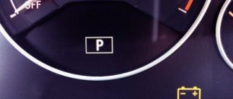
Basic faults
There can be many reasons for a generator malfunction on a VAZ 2110. Here, both minor damage and failure of the entire device are possible. Let's look at the list of main faults:
- Too many additional electrical devices connected. You should turn everything off and check whether the quality of the element has changed.
- If the generator does not charge, the battery may be too large. In this regard, the battery receives a charge, but does not have time to fully charge after a deep discharge.
- Short circuit of the stator or damage to the winding itself. There may also be poor connections between working parts.
- Winding break. In this case, the generator will not charge at all.
- Interturn closure. The coils may fly, so it is worth checking this in detail using a voltmeter.
- Short circuit on the rotor housing. Due to this failure, the entire winding may fail. If this happens, you will have to completely replace it.
- Short circuit in winding phase. With such a malfunction, the generator will become very hot and the battery will not be charged.
- Brush wear. The so-called “chocolate” can also fail. It can be easily replaced by purchasing it at your local auto parts store.
- The malfunction may not lie in the generator itself. The fuse may have failed and will prevent charging. Or the wire coming from the generator is broken. All this should be checked before you take out the unit itself.
Diagram of VAZ 2110 injector 16 valves
1 - headlight 35 - instrument lighting switch 2 - front brake pad wear sensors 36 - ignition switch 3 - reverse light switch 37 - mounting block 4 - engine cooling fan electric motor 38 - recirculation valve switch 5 - sound signal 39 - controller heater 6 - right front door locking motor 40 - hazard warning switch 7 - power window relay 41 - heater control lever illumination lamp 8 - 8 A fuse 42 - glove compartment lighting lamp 9 - starter 43 - glove compartment lighting lamp switch 10 - battery 44 - cigarette lighter 11 - generator 45 - on-board control system display unit 12 - windshield washer motor 46 - ashtray lighting lamp 13 - washer fluid level sensor 47 - brake signal switch 14 - left front door locking motor 48 - locking motor left rear door 15 — power window switch of the left front door 49 — power window switch of the left rear door 16 — coolant level sensor 50 — power window motor of the left rear door 17 — windshield wiper motor 51 — socket for a portable lamp 18 — recirculation valve 52 — clock 19 - micromotor gearbox for heater flap drive 53 - gearmotor for electric window lift on the right rear door 20 - electric motor for heater 54 - power window switch at the right rear door 21 - trunk lock switch 55 - gearmotor for locking the right rear door 22 - power window switch at the right front door 56 - side turn signal 23 - electric window motor of the right front door 57 - parking brake warning lamp switch 24 - door lock system control unit 58 - driver's seat belt sensor 25 - additional heater motor resistor 59 - directional light bulb 26 - brake fluid level sensor 60 - interior light bulb 27 - electric window motor of the left front door 61 — interior air temperature sensor 28 — exterior lighting switch 62 — switch in the front door pillar 29 — instrument cluster 63 — switch in the rear door pillar 30 — rear fog light switch 64 — external rear light 31 — warning lamp fog light 65 - interior rear light 32 - rear window heating indicator light 66 - license plate lights 33 - rear window heating switch 67 - trunk light 34 - steering column switch A - blocks for connecting the rear window washer motor B - blocks for connecting the harness injection system C - to the warning light harness block D - block for connection to the on-board computer E - to the headlight cleaner harness block F - block for connection to the fuel level sensor in the electric fuel pump module G - to the rear window heating element H - block for connecting an additional signal braking J - to the trunk lock motor
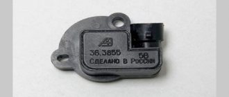
Useful: VAZ speed sensor pinout and DS connection diagram
See the complete diagram in one file below (click to enlarge):
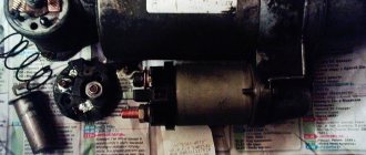
How to check the generator yourself
How to check a VAZ generator using the example of model 2109. Generator type 94.3701 alternating current, three-phase, with a built-in rectifier unit and an electronic voltage regulator, right-hand rotation.
Generator connection diagram . The voltage to excite the generator when the ignition is turned on is supplied to terminal “D+” of the regulator (terminal “D” of the generator) through indicator lamp 4 located in the instrument cluster. After starting the engine, the excitation winding is powered by three additional diodes installed on the generator rectifier block. The operation of the generator is controlled by a warning lamp in the instrument cluster. When the ignition is turned on, the lamp should be on, and after starting the engine, it should go out if the generator is working. If the lamp is brightly lit or glows half-lit, it indicates a malfunction.
The “minus” of the battery should always be connected to ground, and the “plus” should always be connected to the “B+” terminal of the generator. Failure to turn the battery back on will immediately cause increased current through the generator valves and damage them.
It is not allowed to operate the generator with the battery disconnected. This will cause short-term overvoltages to occur at the “B+” terminal of the generator, which can damage the generator voltage regulator and electronic devices in the vehicle’s on-board network.
It is prohibited to check the functionality of the generator “for spark” even by briefly connecting the “B+” terminal of the generator to ground. In this case, significant current flows through the valves and they are damaged.
Electrical circuit of ECM VAZ-21101
1 — VAZ-21101 controller; 2 — block of the ignition system harness to the ABS cabin group harness; 3 — diagnostic block; 4 — immobilizer warning sensor; 5 — immobilizer control unit; 6 — ignition coil; 7 — spark plugs; 8 — nozzles; 9 — electric fuel pump; 10 — block of the ignition system harness to the fuel level sensor harness; 11 — block of the fuel level sensor harness to the ignition system harness; 12 — block of the ignition system harness to the injector harness; 13 — injector harness block to the ignition system harness; 14 — speed sensor; 15 — idle speed regulator; 16 — throttle position sensor; 17 — coolant temperature sensor; 18 — mass air flow sensor; 19 — oil pressure warning lamp sensor; 20 - phase sensor; 21 — oxygen sensor; 22 — crankshaft position sensor; 23 — knock sensor; 24 — solenoid valve for purge of the adsorber; 26 — coolant temperature indicator sensor; 27 — block of the ignition system harness to the instrument panel harness; 28 — block of the instrument panel harness to the ignition system harness; 29 — controller power supply fuse; 30 - ignition relay; 31 - ignition relay fuse; 32 — fuse for the electric fuel pump power supply circuit; 33 — electric fuel pump relay; 34 — electric fan relay; 35 — ignition system harness block to the air conditioner connector; 36 — block of the ignition system harness to the side door harness. 37 — electric fan of the cooling system; 38 — diagnostic connector; 39 — ignition switch; 40 — instrument cluster; 41 — on-board control system unit; 42 — starter relay; 43 — contacts of the 8-terminal blocks of the instrument panel harness and the front harness; 44 — contacts of the 21-terminal blocks of the instrument panel harness and the rear harness; 45 - trip computer.
- A - to the “plus” terminal of the battery;
- B1 — grounding point of the fuel level sensor harness;
- B2, B3 — grounding points of the ignition system harness;
- C - to the starter;
- D - to the driver's door interior lamp switch.
Generator circuit operation
This scheme is considered obsolete and is no longer used in modern cars.
Initial generator excitation
When starting, the initial excitation comes from the battery. Then, when the generator starts working, it transfers part of its current to excitation.
When the ignition is turned on, the current from the battery goes to the plus of the generator, from this point through the mounting block it goes to the ignition switch 30\1. Through the ignition switch contacts, from point 15\1, the ignition system and the generator excitation circuit are powered. Through the 19th fuse, the initial excitation current passes into the instrument panel, through the “battery discharge” light, and comes to connector D on the generator. From this connector via the additional bus. diodes goes to the voltage regulator. The voltage that reaches point L opens the regulator transistor, the excitation current passes into the rotor, and from it, through the open regulator transistor to ground. This closes the initial excitation circuit. The light comes on, confirming that the excitation circuit is intact and the generator is ready for operation. A small current of this circuit magnetizes the rotor; when the rotor begins to rotate, its magnetic poles, replacing each other, create a changing magnetic field that interrupts the turns of the stator winding and an EMF is generated in it, that is, the generator is excited.
Generator excitation during operation, additional rectifier
The voltage at the output of the generator quickly increases and becomes higher than the emf of the battery, now the generator becomes a source, it begins to charge the battery and power all devices.
Engine control circuit VAZ-21102, 21103
Engine control circuit for VAZ-21102, VAZ-21103 (controller M1.5.4N, “January-5.1”).
1 - injectors 2 - spark plugs 3 - ignition module 4 - diagnostic block 5 - controller 6 - block connected to the instrument panel wiring harness 7 - main relay 8 - fuse connected to the main relay 9 - electric fan relay 10 - fuse connected to electric fan relay 11 – electric fuel pump relay 12 – fuse connected to the electric fuel pump relay 13 – mass air flow sensor 14 – throttle position sensor 15 – coolant temperature sensor 16 – idle speed regulator 17 – VAZ-21102 oxygen sensor 18 – knock sensor 19 – Crankshaft position sensor 20 – canister purge solenoid valve 21 – immobilizer control unit 22 – immobilizer status indicator 23 – vehicle speed sensor 24 – electric fuel pump with fuel level sensor 25 – oil pressure warning lamp sensor 26 – coolant temperature indicator sensor 27 – level sensor oil 28 - phase sensor (installed on a car with a 16-valve engine) A - block connected to the wiring harness of the anti-lock brake system (ABS) B - block connected to the air conditioner wiring harness C - block connected to the electric fan wiring harness D - wires , connected to the ignition switch (backlight lamp) E - block connected to the blue-white wires disconnected from the ignition switch (when installing the immobilizer) F - to the “+” terminal of the battery G1, G2 - grounding points The diagram uses the designation of the element number circuit to which this wire is connected, for example “-4-”. In some cases, in addition to the designation of the element number, it is given through an oblique fraction and the contact number, for example “-5/15-”. The diagram does not show the connection points of the pink-black, red and green with a red stripe wires.
Pinout of 8-pin connector
- power supply
- speed sensor (electric speedometer)
- fuel consumption (for BC)
- coolant sensor
- emergency oil pressure
- check lamp
- oil level sensor
- tachometer signal
Generator circuit 9402.3701
Generators that can be installed to replace 9402
9402.3701 ATE – 1 (China LKD)
ELD-A-2110-14V-135A with obg. coupling
3747.3771-93 Electrom. Cheboksary.
2110 START – VOLT Ukraine 135A
Operating principle of the generator
Cars use a three-phase synchronous generator. The operating principle of the generator is based on the law of electromagnetic induction. “Electromotive force in a winding occurs when the magnetic field changes.”
The emf of the generator arises in the winding. The rotor serves to create a changing magnetic field. To magnetize the rotor, an excitation winding is built into it. Current is supplied to it through brushes.
The stator winding is three-phase, connected in a star. There is an alternating voltage at the output of the winding, but a constant voltage is required in the car network and for charging the battery, so the output of the winding is connected to a diode bridge (rectifier).
Diode bridge for generator 9402.3701 BPVO 76-105/11, (Electromodule), BVO 3 -105- 01 (Orbit)
Diode bridge for generator 5102.3771 MP 13.80.3.2 (Orbit)
Electrical circuit of ECM VAZ-21104
1 — block of the ignition coil wiring harness to the ignition system harness; 2 — block of the ignition system harness to the ignition coil wiring harness; 3 — ignition coils VAZ-21104; 4 — immobilizer warning sensor; 5 — immobilizer control unit; 6 — spark plugs; 7 — nozzles; 8 — diagnostic block; 9 — block of the ignition system harness to the ABS cabin group harness; 10 - controller; 11 — electric fuel pump; 12 — block of the ignition system harness to the fuel level sensor harness; 13 — block of the fuel level sensor harness to the ignition system harness; 14 — block of the ignition system harness to the injector harness; 15 — injector harness block to the ignition system harness; 16 — block of the ignition system harness to the side door harness; 17 — speed sensor; 18 — idle speed regulator; 19 — throttle position sensor; 20 — coolant temperature sensor; 21 — mass air flow sensor; 22 — oil pressure warning lamp sensor; 23 - phase sensor; 24 — oxygen sensor; 25 — crankshaft position sensor; 26 — knock sensor; 27 — solenoid valve for purge of the adsorber; 28 — oil level sensor; 29 — coolant temperature indicator sensor; 30 — block of the ignition system harness to the instrument panel harness; 31 — block of the instrument panel harness to the ignition system harness; 32 — ignition relay; 33 - ignition relay fuse; 34 — fuse for the electric fuel pump power supply circuit; 35 — electric fuel pump relay; 36 — electric fan relay; 37 — controller power supply fuse; 38 — ignition system harness block to the air conditioner connector; 39 — instrument cluster; 40 — ignition switch; 41 — electric fan of the cooling system; 42 — on-board control system unit; 43 — starter relay; 44 — contacts of the 8-terminal blocks of the instrument panel harness and the front harness; 45 — contacts of the 21-terminal blocks of the instrument panel harness and the rear harness; 46 — trip computer; 47 - diagnostic connector.
- A - to the “plus” terminal of the battery;
- B1 — grounding point of the ignition coil wiring harness;
- B2 — grounding point of the fuel level sensor harness;
- B3, B4 - grounding points of the ignition system harness;
- C - to the starter;
- D - to the driver's door interior lamp switch.
According to the scheme described above, fuel regulation in a car is carried out. Moreover, it depends not only on the load of the valves in the engine, but also on the corresponding position relative to the throttle valve. With the help of a diagram of electrical wiring and valves, it is possible to understand which of the relays or fuses is malfunctioning and replace it in time. In this case, one of the main roles when supplying fuel is played by electrical equipment (controllers) that regulates the operation of the injector.
Generator output voltage, purpose of voltage regulator
The voltage that must operate in automotive electrical equipment must be maintained at approximately 14 Volts. For this purpose, a voltage regulator is installed in the generator
The voltage regulator is included in the excitation circuit, that is, in the rotor winding circuit, so it is structurally combined with the brushes. The regulator constantly turns the excitation current on and off, thereby maintaining the required generator voltage level.
Generator voltage regulator 9402
Generator voltage regulator 5102
VAZ-2110 wiring diagram
Electrical wiring for the VAZ-2110 is of two types: carburetor and injector . There are slight differences, but the basic principles of operation and wiring are the same. Depending on the location, the wiring differs into: under the hood and in the cabin . All electrical equipment of the car is connected using wires of a certain color. Each element has its own wiring harness through the blocks and fuses.
The on-board voltage is 12V constant, minus on the car body.
Having a wiring diagram and knowing the operating principles of the main components of the car is not at all difficult to find the malfunction and the cause of its occurrence.
Before starting to repair the vehicle's electrical wiring (if this is not related to troubleshooting), the terminals should be removed from the battery.
Electrical diagram of a carburetor ignition system
At the first releases of the VAZ-2110, a carburetor was installed, which was later replaced by an injector, as a more modern and reliable system that ensures economical stable operation of the engine. The wiring of an engine with a carburetor includes almost the same vehicle life support systems as with an injector.
| 1 – block headlight | 37 – instrument cluster |
| 2 – front brake pad wear sensor | 38 – rear fog light switch |
| 3 – fan motor activation sensor | 39 – fog light indicator lamp |
| 4 – electric motor of the engine cooling system fan | 40 – indicator lamp for heated rear window |
| 5 - sound signal | 41 - watch |
| 6 – generator | 42 – rear window heating switch |
| 7 – oil level sensor | 43 - Understeering's shifter |
| 8 – carburetor solenoid valve control unit | 44 – block for switching wires when installing headlights of a different type |
| 9 – heater controller | 45 – instrument lighting switch |
| 10 – recirculation valve switch | 46 – ignition switch |
| 11 – illumination lamp for heater control levers | 47 – connectors for connecting the headlight cleaner wiring harness |
| 12 – switch | 48 – socket for a portable lamp |
| 13 – carburetor limit switch | 49 – directional lamp |
| 14 – oil pressure warning lamp sensor | 50 – brake light switch |
| 15 - spark plug | 51 – interior lamp |
| 16 – carburetor solenoid valve | 52 – on-board control system unit |
| 17 – coolant temperature indicator sensor | 53 – fuel level indicator sensor |
| 18 – ignition distributor | 54 – hazard warning switch |
| 19 - ignition coil | 55 – driver seat belt sensor |
| 20 – starter | 56 – cigarette lighter |
| 21 – heater fan electric motor | 57 – ashtray illumination lamp |
| 22 – additional heater motor resistor | 58 – glove compartment light switch |
| 23 - speed sensor | 59 – connector for connecting the on-board computer |
| 24 – reverse light switch | 60 – glove box lighting lamp |
| 25 – micromotor gearbox for heater damper drive | 61 – side turn signal |
| 26 – recirculation valve | 62 – switch in the front door pillar |
| 27 – brake fluid level sensor | 63 – switch in the rear door pillar |
| 28 – blocks for connecting the rear window washer motor | 64 – parking brake warning lamp switch |
| 29 - accumulator battery | 65 – trunk light |
| 30 – windshield washer motor | 66 – cabin air temperature sensor |
| 31 – washer fluid level sensor | 67 – external rear light |
| 32 – coolant level sensor | 68 – internal rear light |
| 33 – windshield wiper motor | 69 – license plate light |
| 34 – mounting block | 70 – block for connecting the rear window heating element |
| 35 – blocks for connecting the warning light harness | 71 – block for connecting an additional brake signal |
| 36 – external lighting switch |
A
— the order of conventional numbering of plugs in the blocks of the mounting block, instrument cluster, ignition switch and gear motor of the windshield wiper
B
— the order of conventional numbering of plugs in the blocks of the ignition sensor-distributor and speed sensor
Notes:
1.
In the instrument panel wiring harness, the second ends of the white, black, orange, white with red stripe and yellow with blue stripe wires are connected to each other at the same points.
2.
The bends of the wires at the points of entry into the harness indicate the direction of their laying in the harness.
Electrical diagram of a contactless car ignition system
The carburetor is already an obsolete car part. It is less reliable and cannot provide such an accurate supply of the fuel mixture. In later releases, the carburetor ignition system was replaced with an injection system. The controller in this system “reads” the operation of all systems, thereby determining and setting many indicators - calculation of the fuel mixture, etc.
To find a wiring fault, you need to start looking in the contacts. Moreover, you need to check all the wires that are included in the harness: their visual integrity, resistance, reliability of contacts, etc. The underhood wiring has identical plugs.
In addition to the wiring that is provided for the VAZ 2110 - carburetor, "ten" - injector, it is also equipped with a number of fuses that protect almost all of it from the possibility of short circuiting. The fuse and relay box in VAZ-2110 cars is located in the car interior near the driver's seat, to the left and below the steering wheel.
Fuse box VAZ-2110, VAZ-2111, VAZ-2112
VAZ-2110 fuses (number, rating and what they are responsible for)
Structurally, fuses are not provided only for the supply of current by the wire from the battery, in the car starting and ignition circuit, as well as for the wire going to the generator.
To replace a faulty fuse, first find the one that has blown and be sure to eliminate the cause. After that, install a new one of the same value.
Do not replace fuses with jumpers; this may cause blocks and devices to become unusable, as well as a wiring fire!
F1 - 5A - License plate lamps. Instrument lighting lamps. Side light indicator lamp. Trunk light. Left side marker lamps. F2 - 7.5A - Left headlight (low beam). F3 - 10A - Left headlight (high beam). F4 - 10A - Right fog lamp. F5 - 30A - Electric door window motors. F6 - 15A - Portable lamp. F7 - 20A - Electric motor of the engine cooling system fan. Sound signal. F8 - 20A - Rear window heating element. Relay (contacts) for turning on the heated rear window. F9 - 20A - Recirculation valve. Windshield and headlight cleaners and washers. Relay (coil) for turning on the heated rear window. F10 - 20A - Reserve. F11 - 5A - Starboard side marker lamps. F12 - 7.5A - Right headlight (low beam). F13 - 10A - Right headlight (high beam). Indicator lamp for turning on the high beam. F14 - 10A - Left fog lamp. F15 - 20A - Electric seat heating. Locking the trunk lock. F16 - 10A - Relay-breaker for direction indicators and hazard warning lights (in emergency mode). Hazard warning lamp. F17 - 7.5A - Interior lighting lamp. Individual backlight lamp. Ignition switch illumination lamp. Brake light bulbs. Clock (trip computer). F18 - 25A - Glove box lighting lamp. Heater controller. Cigarette lighter. F19 - 10A - Door locking. Relay for monitoring the health of brake light lamps and side lights. Direction indicators with warning lamps. Reversing lamps. Generator excitation winding. On-board control system display unit. Instrument cluster. Clock (or trip computer). F20 - 7.5A - Rear fog lamps.
Fuse box relay (number and what includes)
K1 – relay for monitoring the health of light bulbs; K2 – front wiper relay; K3 – repeater and alarm relay; K4 – low beam relay; K5 – high beam relay; K6 – additional relay; K7 – relay for turning on the heated rear window; K8 – backup relay (not installed on 110 series vehicles);
Electrical diagram of the VAZ-21102 car
| 1 — block headlight | 35 — instrument lighting switch |
| 2 - front brake pad wear sensors | 36 - ignition switch |
| 3 - reverse light switch | 37 - mounting block |
| 4 — electric motor of the engine cooling system fan | 38 - recirculation valve switch |
| 5 - sound signal | 39 — heater controller |
| 6 — gear motor for locking the right front door lock | 40 - hazard warning switch |
| 7 - power window relay | 41 — lamp illuminating the heater control levers |
| 8 - 8 A fuse | 42 — glove box lighting lamp |
| 9 - starter | 43 - glove compartment light switch |
| 10 - accumulator battery | 44 - cigarette lighter |
| 11 - generator | 45 — display unit of the on-board control system |
| 12 - windshield washer motor | 46 - ashtray lighting lamp |
| 13 — washer fluid level sensor | 47 — brake light switch |
| 14 — gear motor for locking the left front door lock | 48 — gear motor for locking the left rear door lock |
| 15 - left front door power window switch | 49 - left rear door power window switch |
| 16 — coolant level sensor | 50 — electric window motor of the left rear door |
| 17 - windshield wiper motor | 51 — socket for a portable lamp |
| 18 - recirculation valve | 52 - watch |
| 19 — micromotor gearbox for heater damper drive | 53 — electric window motor gearbox of the right rear door |
| 20 — electric heater motor | 54 — right rear door power window switch |
| 21 — trunk lock switch | 55 — gear motor for locking the right rear door lock |
| 22 - right front door power window switch | 56 - side turn signal |
| 23 — electric window motor reducer of the right front door | 57 - parking brake warning lamp switch |
| 24 — control unit for the door lock system | 58 — driver's seat belt sensor |
| 25 — additional resistor for the heater motor | 59 - directional lamp |
| 26 — brake fluid level sensor | 60 - interior lamp |
| 27 — electric window motor reducer of the left front door | 61 — cabin air temperature sensor |
| 28 - outdoor lighting switch | 62 — switch in the front door pillar |
| 29 — instrument cluster | 63 — switch in the rear door pillar |
| 30 - rear fog light switch | 64 — external rear light |
| 31 — fog light indicator lamp | 65 - internal rear light |
| 32 — indicator lamp for heated rear window | 66 — license plate lights |
| 33 — rear window heating switch | 67 - trunk light |
| 34 - Understeering's shifter |
A
— blocks for connecting the rear window washer motor.
B
- blocks for connecting the injection system harness.
C
- to the warning light harness block.
D
— block for connection to the on-board computer.
E
- to the headlight cleaner harness block.
F
— block for connection to the fuel level sensor in the electric fuel pump module.
G
- to the rear window heating element.
H
- block for connecting an additional brake signal.
J
- to the trunk lock motor.
The diagram does not conventionally show that in the instrument panel wiring harness, the second ends of all wires of white, black, orange, white with a red stripe and yellow with a blue stripe are connected to each other at the same points.
The following (9) users say Thank You to pioneerxp2 for this post:
The power circuit of these lamps includes a relay-breaker K3, which alternately closes contacts 49a and 49a Register on site 2. It all started with the fact that I began to be wildly annoyed by the breakdowns of the two-piece, it seemed like nothing serious had broken, but there were so many little things, damn it, which was really starting to piss me off. Locking the trunk lock. Indicator lamp for turning on the high beam.
The only nuance of switching from a carurator to an injector is the need to install additional wiring from the fuel pump to the on-board computer.
F14 - 10A - Left fog lamp. They turn on regardless of the relay activation. To prevent this situation, it is better to connect the relay control wire to the terminal from the ignition switch in red in the diagram. It is regulated only by the limit switch
Article Archives
Depending on the location, the wiring differs into: under the hood and in the cabin. Injector In addition to the wiring, which is identical for the carburetor and injector, the latter is additionally equipped with fuses and sensors.
This is done to reduce the load on the battery when the engine is not running and prevent its discharge. It is regulated only by the limit switch. Side light indicator lamp.
But this does not take away the fact that many have dozens of them under the hood with a carburetor. F3 - 10A - Left headlight high beam. These positions correspond to the inclusion of indicator 5 on the device. F2 - 7.5A - Left headlight low beam. Connecting the VAZ ECU harness