Why do you need to install a relay in a car? Let's start with the definition:
Relay is an electrical device (switch) designed to close and open various sections of electrical circuits for given changes in electrical or non-electrical input quantities. Types of relays may differ in the control signal and in design, we will not dwell on this, especially since all this is on the same Wikipedia. We only note that electric (electromagnetic) relays are most widespread.
It is difficult to understand why a relay is needed from the definition, so let’s break it down in simple words: The relay is designed for switching large load currents. In other words, it is a switch, or even simpler - the principle of operation of a relay - with a small current (for example, a button signal) to turn on circuits with a large current. And a relay is used when the actuator (starter, generator, fan, heated mirrors, horn, etc.) consumes more current (up to 30-40 amperes).
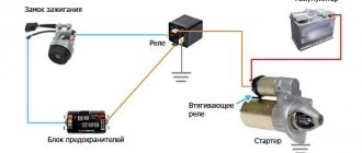
FOR EXAMPLE: In order to start the engine with a small button, it is necessary to turn on the starter, which consumes from 80 to 300 amperes. If you do not use a relay, then the button will not withstand high current and will melt, as well as the wiring, which is not intended for high currents. Therefore, a connection is made through a relay (a relay is installed between the button and the starter), which, based on a small current impulse from the button, closes powerful contacts within itself, thereby turning on the starter. How does this happen ? **************************************** **************************************** ******************* Relay device
An electromagnetic relay consists of: an electromagnet (an electric wire wound on a coil with a core of magnetic material). armatures (a plate made of magnetic material that controls contacts through a pusher). switches (can be making, breaking, switching).
Relay Contacts: Pins 85 and 86 are the coil. Contact 30 is a common contact, always present in the relay. Without supplying voltage to the winding contacts, it is permanently closed to contact 87a. Contact 87A is a normally closed contact. Contact 87 is a normally open contact. Power contacts are always marked 30, 87 and 87a.
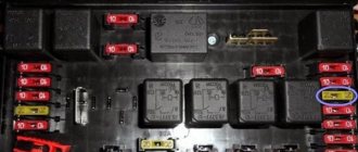
Every small car enthusiast knows that there are some kind of relays and fuses in a car. After all, in the event of an electrical fault in a car, the first thing to check is the relay and fuse box! So what is special about these relays, how do they work and what is their essence? Are they really necessary and irreplaceable? I will talk about this in the article. Since they, that is, relays, are in the car, then for some reason they are needed. And it was with the purpose of the relay in the car that I wanted to start. Relays have several tasks and functions.
Why do you need a relay in a car?
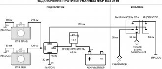
First, and most importantly, is the ability to control power currents for power loads. That is, when the input signal to the relay is literally several mA, we already get several tens of Amperes at the output. No, the relay does not amplify the signal, it only switches currents, more on this later when it comes to the principle of operation. Secondly, the relay can functionally switch the load between 2 or more different electrical circuits, while doing this from 1 control signal. That is, at the input we again have 1 input voltage of several mA, and the power contacts switch among themselves for different circuits. Let's say the low beam headlights were working, and the high beam headlights turned on. Third, the relay, due to its audible response signal, makes it possible with a high degree of probability to diagnose its correct operation and, as a consequence, the operation of the supply circuit. That is, if there is a signal, then most likely there is also voltage in the supply circuit. If there is no click, then you should check the fuse! Also, the sound of the relay when the turn signals are turned on indicates that they are most likely working, which is important when changing lanes. And if the turn signal lights up frequently, they indicate a burnt-out lamp. Fourth, this is a consequence... By controlling power signals, they can save on copper wiring in the car, since the relay unit is most often installed in the engine compartment, closer to the power control circuits. That is, thin copper wires go to it, from the controls in the cabin, and thick copper wires go out to the power loads in the engine compartment. (headlights, ignition switch relay, diesel heaters...)
Operating principle of undervoltage protection
Regardless of the scope of application of ZMN, its principle of operation remains unchanged. Let us explain the protection operation algorithm using the example of an arbitrary object, where several electric motors are used for the production process and auxiliary equipment is connected. Let’s say a short circuit occurs on the line supplying the facility, causing the input switch to trip (current protection). After repair work is completed and power is restored, the following actions occur:
- Automatic start of engines, which leads to high starting currents and, accordingly, to a decrease in network voltage.
- Protection relay contacts disconnect non-critical mechanisms, that is, equipment that does not take part in the production process or whose downtime is not critical for the technological cycle. This leads to normalization of the current and increase in voltage to the nominal level, which allows for regular autostart of the main components.
How does a car relay work (four- and five-pin)
The relay is one of the first radioelements that people invented! Ever since Faraday discovered the features of self-induction current in 1831, that is, he found out that the current in a conductor creates an electromagnetic field capable of attracting magnetizable materials, it was from that time that there were all the prerequisites for someone to take advantage of this and create relay! Actually, this was created around the same time, and was mentioned for the first time in the patent of Morse, the same one who invented the telegraph (1838). And now we, in the footsteps of the greats, will understand the operation of a car relay, which is not very different from what was invented in the century before last. So, there is a coil wound on a core. When current passes through a wire, an electric field is formed in it. Due to the large number of wires wound in one direction, the electric field is added up and intensified. This field is capable of attracting magnetizable material, but as you understand, only while the current is flowing in the conductors, that is, in the coil. And now the current flows, a magnetic field is created, a group of contacts attracted by this field is triggered... Now it’s time to turn to the illustration.
Again. As soon as an electromagnetic field is created, it attracts the actuator associated with the contacts. As a result, they close or open. This is how the switching of power circuits occurs, which I spoke about earlier. Here the imagination of relay designers or common sense pragmatism will dictate how many contacts we need to switch in a given case. Hence the relay can turn out to be four-contact, where 2 contacts are the power supply to the coil and 2 are those that are switched. 5 contact, when 2 contacts are for powering the coil and 3 for switching between each other. And similar variations...
Types of relays by type of incoming parameter
According to this parameter, relays are divided into: current, power, frequency, voltage, pressure, acoustic values, amount of gas. Devices can be maximum and minimum. Relays that operate when a given value is exceeded are called “maximum”, and when it falls below a given level, they are called “minimum”.
Current relay
Current relays react to sudden changes in current and, if necessary, turn off an individual load or the entire power supply system. The maximum current value at which it is necessary to disconnect consumers is set by the regulator.
Voltage relay
Voltage relays react to voltage levels and are switched on via voltage transformers. Used to control voltage phases in electrical networks and protect electrical appliances. The basis of such a relay is a quick response controller that monitors voltage deviations outside the established limits. The generally accepted standard for operation of such relays is below 170 V and above 250 V.
Frequency relay
They are used to control the frequency of alternating current, which should be equal to 50 or 60 Hz in single- and three-phase networks. Usually have fixed response delays. The opening thresholds of the controlled circuit can be adjusted. The operating mode of this device may include the presence of a “memory” of an accident.
Power relay
The power limiting device operates similarly to a load current limiter. If the set power threshold is exceeded, the consumer is switched off. Power limiting relays are often equipped with an automatic reset function. That is, after the load is reduced, the operation of the equipment resumes automatically.
Pressure switch
A pressure switch is an important device used in pumping equipment to control pressure differences in water, oil, oil, and air. There are two main types of such devices – electromechanical and electronic.
Electromechanical relays have a special element in their design that responds to changes in pressure in the system - a flexible membrane that bends under the pressure of liquid (air) in the system. It is connected to two springs, one of which is adjusted to the minimum permissible pressure, and the second to the difference between the upper and lower limits of pressure in the system. When the pressure in the system drops below the minimum threshold, the relay turns on the pumping equipment, and when the upper threshold is exceeded, it turns off. These are simple and reliable devices, but not very easy to use. The operator has to regularly check the settings and adjust them if necessary.
Electronic devices have a more complex design. Limits can be set very precisely and are not required to be monitored during operation. Electronic devices are sensitive to water hammer, so they are equipped with small hydraulic tanks (volume - approximately 400 ml). An electronic pressure switch is installed between the pumping equipment and the first water collection point.
Acoustic relays
Acoustic relays respond to changes in acoustic quantities - the frequency of the sound wave, its pressure or the acoustic characteristics of materials - absorption and reflection coefficients. The operating principle can be mechanical or electrical. Mechanical acoustic devices have a membrane that bends under the pressure of sound waves, and when a certain pressure value is reached, the contact closes. Electrical acoustic devices include: a receiving organ (microphone, filter), an amplifier, and an output electrical relay.
Devices that respond to any noise are often used in conjunction with a lighting system. They react to any noise in the room and give a signal to turn on the light. They are usually installed in corridors and staircases. Acoustic relays are also widely used in security systems and “smart” toys.
Gas relays
These devices are used to provide gas protection. They are a metal body embedded in the oil line. The relay is normally filled with oil and its contacts are open. As the gas content increases, they fill the upper part of the relay, simultaneously displacing the oil. The float included in the design lowers as the oil level decreases, rotates around its axis and causes the contacts in the signal circuit to close. The generated signal warns of high gas contamination in the environment.
Designation of a car relay on the diagram, how to connect
After everything has been clarified with the principle of operation, you can move on to formalities. Also, how is a relay indicated on a diagram or how to sketch it when creating such diagrams. The relay in the diagram is designated as a coil; it is a rectangle with two terminals and a separate group of contacts. That is, we draw as many contacts on the diagram. Here the diagram describes not only the number of contacts, but also their position. For relays, it can be normally closed (NC) or normally open (NO). If, in the absence of voltage on the relay coil, the contacts are open, then the relay is normally open...
Often the connection diagram is right on the body of the relay itself. At the same time, there are generally accepted standards. 85, 86 - terminals are the power supply to the coil, while 85 is connected to “+”.
In most cases, changing the connection between 85 and 86 contacts is not fundamental, but if the relay is protected against induction current and has a diode, then 85 is only positive, otherwise there will be a short circuit.
30 is a contact for the incoming power signal and 87, 87a are outgoing switched power contacts.
* - typical relay connection diagram.
Types of relays by purpose
According to their purpose, these devices are of three types - control, protection, alarm.
Control relay
These relays are primary. Mounted directly into the electrical circuit. Their role is to turn on and off individual elements of the circuit. They can be used independently or as components of low-voltage complete devices - boxes, panels, cabinets.
Protection relay
Perform the functions of turning on, turning off and protecting devices with thermal contacts - electric motors, fans. When the temperature is exceeded, the thermal contacts open. The equipment can resume operation only after the thermal contacts have cooled to the set temperature.
Alarms
Such relays are installed in security systems of vehicles, enterprises, and local areas. They are used to generate a signal when a set value of a parameter that is under control is reached (current, voltage, frequency, pressure, temperature, acoustic parameters and others).
Characteristics of automotive relay
Since the relay is designed to work with high currents, one of the important characteristics is the current with which it can work. That is, there are markings 20A, 30 A, 40 A and more. It is necessary to pay attention to this indicator when selecting a relay for a load of known power. After all, such large currents with an on-board voltage of 12 volts actually do not produce such a large total power. That is, if we have 55 W lamps on the headlights, then the total is 110 W. Using the formula P=U*I, the current is 110:12=9.1 A. As a result, it turns out that one relay can simultaneously switch 2 groups of headlights, no more. If this is a whole “chandelier”, then we select the relay current based on the load power, using the formula above... An example is given.
Major relay manufacturers
Aleph International - more than 30 years in the market of electronics, electrical goods and automation equipment. The product is considered one of the most reliable.
Axicom is a division of the Swiss company Alcatel Switzerland Ltd. Since 1999, it has been part of the Tyco Electronics . Produces extremely high quality products. All relay devices offered on the Russian market fully meet the requirements of domestic standards for electrical reliability and dielectric strength;
CIT RELAY & SWITCH (Zhejiang, China) - the company specializes in relay devices used in telecommunications, automotive and security. It has a wide range of products, the main advantage is the affordable price of the products;
Finder is a European manufacturer specializing in the production of relays and timers. It ranks 3rd in Europe in the production of electromechanical relay machines for industrial and domestic use. All products are certified to ISO 9001 and ISO 14001 standards.
NAiS products under this brand are manufactured by Matsushita Electric Works (Japan). Products are certified according to ISO 9001:2000 standards. The product range includes electromechanical and PhotoMOS relays, various controllers and microswitches for both industrial and domestic use.
How to check the operation of a car relay
It remains to mention how to check the relay.
The simplest thing, as I already mentioned, is to hear the sound of operation. If it is, then the relay most likely has nothing to do with your malfunction. However, the “words most likely” are most likely not accidental here. The relay contacts may completely burn out, and as a result the relay will stop switching the circuits, that is, performing its main tasks. You can check the absence of resistance like never before using a trivial multimeter. We set the resistance to continuity and check. There are several Ohms on the coil, and even less than 0-1 Ohms on the group of contacts. Actually, now you know much more than before you started reading this article, all that remains is to repeat everything again in the video. This question sooner or later arises for almost all car owners. These little black boxes, scattered throughout the car, do something inside themselves, click, tick and sometimes break. What is a relay?
In general, relays are different. There are a huge number of relays, divided by type of operation, voltage, scope of application, and so on. But in this article, we will deal with conventional electromechanical relays that are used in any cars that you see around.
What is a relay?
A relay is a device that allows you to close or open an electrical circuit based on a specific signal. In the classic version, such a signal is a regular voltage, but applied to separate contacts. Why is this necessary?
Relays are used, firstly, so that powerful consumers of electricity can be controlled using weak control elements. Secondly, the relay makes it possible to turn on several consumers with one button.
Real life example: ordinary car headlights. Halogen headlight bulbs typically have a power rating of 55 watts. There are two of them, which means that the total power is already 110 watts. When you press a button in the cabin or turn the headlight switch, the light bulbs in the headlights light up and create a load in the wires just for these 110 watts. This power is not small, and without a relay all of it would pass through the switch. In order to implement this, it would be necessary to run thick wires into the interior, and the switch itself would be powerful and most likely ugly. It would hardly be possible to place it in the steering column switch (as, for example, on Japanese cars).
If we take into account that there are a lot of powerful consumers even in classic Zhiguli cars ( cooling fan , headlights, heated rear window, starter), then a huge number of thick wires would have to be installed into the cabin and powerful controls would have to be made.
The relay frees you from all this. To understand how it does this, let's look at its internal structure.
How does the relay work?
The basis of the relay is an electromagnet and a contact group. The contact group, in the simplest case, consists of four contacts. Two of them are power supply to the electromagnet, the rest are power supply to the consumer connected via a relay (for example, a heated rear window). These contacts have their own names - control circuit and power circuit (or control contacts and power contacts). Accordingly, the power circuit is powerful contacts that pass current through themselves to the consumer (for example, 110 Watts for headlights). The control circuit operates with a weak current and is designed to power an electromagnet. In this case, “plus” is applied to one (certain) contact of the electromagnet, and “ground” is applied to the second contact, that is, it is usually connected to the car body.
Powerful wires are connected to the power contacts, and it turns out that the relay, as it were, breaks these wires into two parts so that it is possible to control the current inside them.
Types of electromagnetic relays
The first classification is based on nutrition. There are electromagnetic relays for direct and alternating current. DC relays can be neutral or polarized. Neutral ones are triggered when power is applied to any polarity, polarized ones react only to positive or negative (depending on the direction of the current).
Types of electromagnetic relays by type of supply voltage and appearance of one of the models
According to electrical parameters
Electromagnetic relays are also divided according to sensitivity:
- Trigger power 0.01 W or less - highly sensitive.
- The power consumed by the winding when triggered is from 0.01 W to 0.05 W - sensitive.
- The rest are normal.
First of all, you need to decide on the electrical parameters
The first two groups (highly sensitive and sensitive) can be controlled from microcircuits. They are quite capable of delivering the required voltage level, so that intermediate amplification is not required.
According to the level of switched load there is the following division:
- No more than 120 W AC and 60 W DC - low current.
- 500 W AC and 150 W DC - increased power;
- More than 500 W AC - contactors. Used in power circuits.
There is also a division based on response time. If the contacts close no more than 50 ms (milliseconds) after power is applied to the coil, it is fast acting. If it takes from 50 ms to 150 ms, this is a normal speed, and all those that require more than 150 ms for contacts to operate are slow.
By execution
There are also electromagnetic relays with varying degrees of tightness.
- Open electromagnetic relays. These are the ones with all the parts “in sight”.
- Sealed. They are sealed or welded into a metal or plastic case, inside of which there is air or an inert gas. There is no access to the contacts and coil; only the terminals for supplying power and connecting circuits are accessible.
- Covered. There is a cover, but it is not soldered, but is connected to the body using latches. Sometimes there is a wire loop that holds the lid in place.
The differences in weight and size can be very significant.
And another principle of division is by size. There are microminiature ones - they weigh less than 6 grams, miniature ones - from 6 to 16 grams, small-sized ones weigh from 16 grams to 40 grams, and the rest are normal.
We recommend reading: About the use of the NE555 timer and its analogues
The nuances of turning on running lights
And the more parts, the less reliability. I do not recommend connecting DRLs using this scheme. This seems complicated, but let's look at an example and everything will become clear. Now, if you try to start the car with the security switched on, contact 30 will open with contact 87A and will not allow the engine to start. You have no way to turn off the DRLs until you remove the key from the ignition. Actually, the current reserve never interferes - but this mainly applies to some kind of non-standard electrical equipment of the car that is connected independently. Likewise, 14.8 volts, to which the voltage in the on-board network rises when the engine is running, does not harm them. Its polarity is indifferent to the relay. In this form, the scheme has a significant drawback. There are, of course, more complex relays, with several groups of contacts in one housing - making, breaking, switching. Signal inversion and load control circuits. We connect to low-current transistor alarm outputs.
We connect the other end of the wire to pin 87A. How a 5-pin relay works and works
What to look for when purchasing?
For a motorist who decides to buy a relay in a specialized store when purchasing and subsequently installing it, it is very important to spend a couple of minutes studying the device. There is one important point in this issue and it concerns the fact that the location of the relay is not always standard. Some relay manufacturers equip it with a non-standard arrangement of contacts. In addition, the motorist should also be aware that long-term operation under high loads almost always negatively affects the performance of the element and can even lead to structural failure. Sometimes, at the moment of peak power, a spark may jump, which is likely to lead to the formation of carbon deposits on the contacts. Accordingly, after this, a disruption in the stable operation of the relay is quite possible. In some situations, excess heat and current can build up at poor connections. And this, in turn, will lead to heating of the contact zone and possible melting of the part. The deformed area will subsequently provoke a displacement of the contact fastening and lead to gaps.
More details about the automotive relay and its operation will be discussed in this video:
Published: October 08, 2022
Connection Via Relay 4 Pin Connection Diagram
An electromagnetic relay operates in a fraction of a second, while semiconductor switches can switch millions of times per second.
For ease of understanding, the circuits below are shown without using a stabilizer. Both schemes have a common drawback. If we briefly describe this figure, we get the following: DRLs should be installed at a height of to mm; The distance between adjacent edges of the DRLs must be at least mm; The distance from the outer side surface of the car to the nearby edge of the DRL should be no more than mm. Four-pin relay, connection. In other words, it is a switch, or even simpler - the principle of operation of a relay - with a small current, for example, a button signal to turn on circuits with a high current. We turn on the headlights or low beams, the DRLs go out. To do this, it is advisable to have minimal knowledge in electrical engineering.
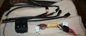
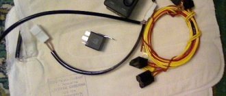
These are ordinary relays from a set of alarms and other additional equipment. This is written in detail here.
Therefore, you need to approach the choice of switching equipment wisely. The relay can be 1-channel, that is, contain 1 switching pair. RELAY. Easy connection