Modern cars are equipped with active safety systems that help avoid loss of control of the car in various driving situations. Some models use more than ten such systems. The first was anti-lock braking system (ABS), which is still common today, and is used even on budget versions. ABS is also the basis for a number of other systems.
Why is ABS needed in a car?
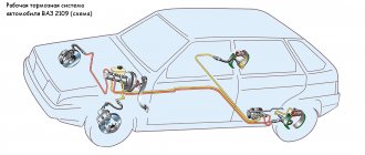
ABS is needed to prevent the wheels from completely locking when braking, which eliminates the possibility of skidding and reduces the braking distance. The theory behind the anti-lock braking system is that when braking, sliding friction occurs between the locked wheel and the road surface, the force of which is lower than rolling friction (when the wheel rotates). In addition, when sliding, lateral forces prevail over longitudinal ones and it is easier for the wheel to “go” to the side than to maintain a given trajectory - a difficult-to-control skid occurs. But if the wheel turns during braking, the car will not skid and will maintain its trajectory, and the braking system will work with maximum efficiency.
Change or repair
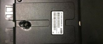
As a result of diagnosing the device, it is possible to determine which sensor node is damaged. If the tester readings tend to zero, this indicates a short circuit in the connection wires; “infinity” indicates a violation of the integrity of the coil winding. There is an opinion that repairing wiring does not cause any problems, but a faulty sensor is easier to simply replace. It’s hard to disagree with the first thought, but the next “point” can be disputed.
The fact is that the cost of some sensors reaches 14–18 thousand rubles, and you will have to wait for their delivery for a long time. Having certain skills, a reserve of patience and natural ingenuity, it will be much more useful and faster to repair the device than to pay for a long-awaited expensive order. Please note that this advice is only advisory in nature - the final verdict remains yours. If the decision to repair has been made, we will be happy to help you carry it out correctly.
What does the anti-lock brake system consist of?
ABS includes two components - electronic and executive module. The first controls the speed of rotation of the wheels on the car and, based on this, sends signals to the module, which prevents the wheels from completely locking.
Electronic component
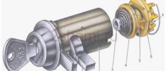
The electronic component includes a control unit and tracking devices installed on the wheel hubs and an abs sensor.
Sensors are the main element of the entire system, since the operation of the ABS depends on their readings. Previously, passive sensors were used on cars. Modern models use active sensors. Both options consist of two elements - a tracking device, installed on the stationary part, and a master device, located on the rotating part of the hub.
Operating principle of ABS sensors
In passive sensors, the tracking component creates a magnetic field. The setting element, passing through this field, leads to its changes. As a result, a pulse voltage is induced in the tracking component, which acts as a signal for the electronic unit.
In active sensors, the operating principle is different. In them, a changing magnetic field is created by master components (multipole rings). The tracking elements are supplied with voltage from a third-party source. The influencing field leads to changes in voltage parameters (in magnetoresistive sensors the resistance changes, in Hall elements the voltage itself changes). These changes are sent to the unit, which uses them to calculate the wheel speed.
Video: ABS - pros and cons of the anti-lock braking system
The electronic unit is a control element. Based on the signals received from the sensors, it determines the rotation speed of each wheel and, based on the information received, sends signals to the executive module to make adjustments to the operation of the braking system.
Executive module
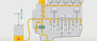
You can influence the brake mechanisms, through which the wheels slow down, by changing the pressure in the brake system drive. Therefore, the executive module is embedded in the brake drive and lines coming from the main brake cylinder approach it, and pipelines extending from it to the brake mechanisms come out of it.
The executive module includes:
- intake and exhaust valves;
- hydraulic accumulator;
- return pump with electric motor;
- damper chamber.
There is one set of valves (inlet and outlet) for each brake mechanism. One damper chamber and one hydraulic accumulator are used per circuit. As for the pump, there is one per executive module. The elements are connected to each other by pipelines.
The module rings the drive line, which allows, if necessary, part of the working fluid to be pumped through the formed ring from the module output to the input.
How to repair wiring
We remove the wheel, and then the locker (for the front wheel, turning out the fastening screws) or the protective shield (for the rear wheel, turning out the two fastening nuts “10”). Press the latch and disconnect the block with wires from the ABS sensor. We inspect the connector and make sure there is no corrosion or damage. In case of damage, we restore the integrity of the wires:
We treat it with a special means for cleaning electrical contacts (for example, graphite grease) and clean the contacts from oxides. We clean the wheel speed sensor and the surface around the sensor from dirt.
Attention! Keep ABS sensors away from magnets as this may cause damage.
Principle of operation
The operation of the executive module is cyclical and includes three phases:
- Increase in pressure. When braking, the brake cylinder creates fluid pressure, and it moves freely along the line to the mechanisms. Direct movement of fluid results in an open inlet valve, while the outlet valve is closed. As a result, the pressure on the mechanisms increases and the wheel slows down intensively.
- Hold. If the control unit, based on sensor readings, has detected faster deceleration of one of the wheels, then it sends a signal to close the inlet valve of this wheel (the exhaust valve is also closed). As a result, the increase in pressure on the mechanism stops, the wheel stops slowing down, since the friction force on the mechanism stops at the same level.
- Reset. In the case when the unit “notices” that the wheel on which the holding phase was applied is still slowing down faster than the others, it sends a signal to open the exhaust valve (the intake valve remains closed) and the pressure in the line is released due to the flow of part of the liquid into the one created by the module ring - the brake mechanism is released.
When the outlet valve opens, the liquid first enters the hydraulic accumulator (acts as a container for collecting excess). If a lot of liquid is discharged and the battery volume is not enough, a pump is activated, which pumps the excess into the line at the module input.
Since the operation of the pump creates a pulsation of liquid, to eliminate this negative effect, after the pump it is first supplied to the damper chamber, where the pulsation is smoothed out, and only then into the main line.
The operating speed of ABS is very high. When the car slows down, the system operates up to several hundred times, changing phases to slow down the car. ABS works constantly on the car and cannot be turned off.
Adviсe
p, blockquote 48,0,0,0,0 —>
To ensure that ABS sensor malfunctions occur as rarely as possible, you should:
p, blockquote 49,0,0,0,0 —>
- try to avoid driving in areas with low bushes so as not to damage the ABS cable;
- periodically clean the gap between it and the metal comb with a soft brush;
- repair of wheel hubs and suspension arms should be trusted to mechanics who have an understanding of the operation of the ABS system.
A simple circuit of a homemade charger for a car battery that helps in extreme cases.
How to check the resistance of high-voltage wires with a multimeter.
Video - how to check which ABS sensor does not work on a BMW e32/34:
p, blockquote 51,0,0,0,0 —> p, blockquote 52,0,0,0,1 —>
- How to check the coolant temperature sensor and identify its malfunction
- How to check the ignition coil with a multimeter or brute force method
- How to independently check the starter for performance
- Which brake pads are best to choose for your car?
I encountered a problem with the ABS sensor a year ago. I came to pick up the car in the morning, started it, and by the time I left the garage, more than 5 minutes had passed, and the ABS light still hadn’t gone out. And if everything is fine, it should have gone out when the car started moving. So I left all day. In the evening, assuming that the reason was a broken wire, I decided to check it using a tester. If the resistance is 0 ohm or close to it, then there is a short circuit, if it is infinity, then there is a break. When checking the sensors on the connector, the rear left one turned out to be inoperative. I rang in both directions - same thing. I was about to climb to remove the sensor, and then I remembered that you can check the sensor by rotating the wheel. I jacked it up and asked my neighbor to hold the multimeter connected to the connector. I spun the wheel, and the neighbor said that sometimes there was voltage, sometimes there wasn’t. I decided to check the wiring. I moved the connector - there was a circuit, then there wasn’t. I had to remove it - the reason is simply simple, the solder fell off from the connector contact, everything was held on by the cambric.
Not an easy problem, the ABS sensor is an important thing and you can’t do without it. I encountered this problem, the reason turned out to be unsoldering of the contacts. Apparently, this is the most common cause of failure, because the sensor itself is quite simple and there is essentially nothing to break.
I remember a year ago this ABS ate my brains out. The icon lights up and that’s it! And I contacted specialists, and they did various tests with this sensor. It was still burning. The most interesting thing is that everyone kept saying that it was just covered in snow. But now spring has come, and the icon is still burning. As a result, when I changed the rear pads, everything was gone within an hour! I've been driving for a year now and haven't seen this badge.
Just recently I had a problem with my ABS. Already, all kinds of diagnostics didn’t do any good 0. Who says what. My husband and I will try to check everything again. I hope you are lucky and everything turns out to be much simpler and cheaper.
Well, the easiest option in my opinion (if there is no diagnostics) is to measure the resistance on the sensors with a megger
Any diagnostician can check or, if indicated, there is a diagnosis himself. You can use a tester - the main thing is that everyone has the same resistance.
When did ABS first appear?
ABS is an anti-lock braking system that prevents the wheel from locking during heavy braking, leaving the car in control.
The development of this system began back in the late 30s, and only in 1978 did motorists get the opportunity to install ABS on premium cars as an additional option. The structure of the ABS unit is a system of sensors that take into account the speed of rotation of the wheels, a brake fluid pressure sensor, the control module itself and the hydraulic unit as the final performer.
Why does the ABS and ESC light come on?
ABS malfunction may be caused by:
- failure of wheel rotation sensors;
- malfunction of the hydraulic valve block;
- damage to the wiring.
If the ABS malfunction indicator light comes on, you must contact a service station as soon as possible for diagnostics (read error codes) and repairs.
The most common cause of ABS failure is damage to the wiring near the ABS sensor connector. It is located under the fender liner, but is still not well protected from moisture and dirt.
As a result, the wires oxidize and break, and the ABS lamp lights up.
How does the ABS sensor work?
Initially, passive sensors were installed on cars, which could not detect wheel speeds of less than 5-7 km/h. Since the nineties of the last century, active sensors began to be installed in ABS. The main difference from passive sensors is that active sensors operate from a power source.
ABS sensor on the front wheel
At first, the ABS system sensors were magnetoresistive, then more accurate sensors using the Hall effect began to be installed in anti-lock brake systems.
At first these were magnetoresistive sensors. They consisted of an energized induction ring that was mounted on the wheel hub. During rotation, a magnetic field was created, which forced the direct current electrons to change their trajectory, thereby increasing the resistance. It was the information about the change in resistance that the ABS sensor transmitted to the control unit. They could detect the rotation speed from the moment the car started moving. The design of modern ABS sensors in cars changed back in the last century. And this is due to the use of the Hall effect in them. Now its work is that a semiconductor wafer is installed in the sensor itself, a permanent magnet ring is installed on the hub, next to the brake discs , and when the wheel rotates, a magnetic field is created, which causes electrons to move to one of the edges of the wafer, the microcircuits convert the signal and transmit it to ABS control unit. This sensor is more accurate, since it does not have a pulsed nature, but the microcircuits have increased the cost of the system, in addition, the microcircuit may fail due to road irregularities.
Service
Maintenance consists of inspecting all components and replacing them in case of wear. All service looks like this:
- checking the brake pedal travel;
- checking and possible adjustment of the parking brake (Kalina has a handbrake from “nine”, so it must be tightened often);
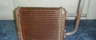
- inspection of all tubes and hoses;
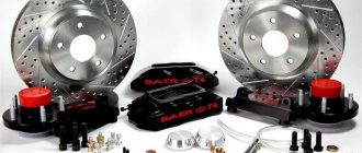
- inspection of the condition of brake discs, drums and pads;
- checking the brake fluid level and replacing it approximately every 40 thousand kilometers.
How does the ABS sensor work in simple words?
Driving a vehicle with ABS and without anti-lock wheels
When a wheel is blocked, a signal is sent from the sensor to the ABS control unit, which in turn sends a command to reduce the braking force on the wheel.
The operating principle of the ABS sensor is as follows. During sudden braking, the system collects information that the wheel is not rotating, while the car is still moving. Next, the ABS sensor transmits information to the main brake system, indicating that it is necessary to reduce the braking force on this wheel, due to which the wheel lock is removed and the car comes out of the skid.
Brake system "Lada Kalina": diagram, mechanism and system design
One of the disadvantages of the ABS of this car, like many others, is the possible failure of the electrical part of the control unit. Bad roads and shaking may destroy the soldering (or the soldering from the factory was initially of poor quality), and the ABS will fail. If liquid gets into the block, a short circuit occurs, oxidation and subsequent rotting of the components. The main thing is not to hesitate and immediately take it to a service center or manually clean the board and solder the questionable elements. ABS repairs are carried out by automotive electricians.
How to brake correctly in a car with ABS?
ABS system control unit on a car
To improve the performance of the ABS system, you need to remember and follow a few simple rules.
In theory, everything is simple in case of emergency braking - pedal to the floor, and the ABS unit will do the rest itself. But in practice this does not always happen. In order to get the most from the anti-lock brake system, significantly increase braking efficiency, reduce the likelihood of wheel locking and skidding of your car, improve maneuverability on wet asphalt, and reduce tire wear, you need to follow simple rules:
- The brake pedal must be pressed smoothly, with increasing force.
- Do not release the pedal during reverse kickback.
- Use tires according to the season.
- Do not completely rely on the system, since the ABS unit does not always work correctly.
But, like everything, the system has its drawbacks. On a road with a loose surface, be it snow or sand, ABS will not help you, but, on the contrary, will lengthen the braking distance.
How to modify the design
To protect the wiring harness from the environment, you can use a D-shaped seal. We lay the wires in it and wrap it with electrical tape. We put everything in the corrugation. We glue the cover covering the ABS sensor connector around the perimeter with the same sealant. This will prevent moisture and dirt from entering the area where the sensor and connector are located.
Attention! If the ABS fails, the brakes remain operational, but the braking efficiency is reduced, which is especially dangerous on some surfaces. See why.
1200 rub. for the photo report
We pay for photo reports on car repairs. Earnings from 10,000 rubles/month.
Write:
Some car enthusiasts are afraid that when the ABS light is on, it somehow affects the operation of the braking system as a whole. They urgently begin to scour the entire Internet in search of an answer to why the ABS light is on and what to do. But don’t panic so much, the brakes on your car should be in perfect order, only the anti-lock system will not work , which, in principle, is not critical, although in some emergency situations it helps a lot. To understand the system, I recommend reading about ABS.
Features of the system
ABS is installed on the braking system and makes its own adjustments to its operation. From the name itself you can understand that its task is to prevent wheel locking during braking.
The peculiarity of car wheels is that their rolling friction force is higher than sliding friction. That is, a wheel that rolls has better adhesion to the road surface than a wheel sliding along the road surface, which happens if it is completely blocked. As a result, the braking distance of the car increases.
Also, wheel sliding does not always occur in a straight direction, since lateral forces can prevail over longitudinal ones, which is why the trajectory of movement of such a wheel changes. The result of this is unpredictable and uncontrolled movement of the machine.
But if you create a force on the braking mechanism that will slow down the rotation speed as much as possible, but without blocking it (keeps it on the edge), then the braking distance will be shortened and the car will not lose control.
In cars without this system, experienced drivers use the method of repeatedly pressing the pedal (intermittent braking) to obtain maximum braking effect. To prevent the wheels from becoming blocked, the driver presses the pedal when braking, then releases it and repeats this many times.
The essence of this method is very simple - to catch the moment on the brake mechanisms when they slow down the wheels as much as possible without causing them to lock, but this is not always possible, especially if the wheels are moving on different surfaces.
Intermittent braking (press and release) does not allow the wheels to completely lock, since the driver simply periodically loosens the force on the brake mechanism. ABS uses the same principle.
Overview of individual elements
Diagram of the Kalina brake system:
| 1, 5, 13, 16 | Brake mechanism of the Kalina front wheel, including pads, caliper, disc, cylinder |
| 13, 16 | Brake mechanism of the Kalina rear wheel - pads, drum, cylinder |
| 2, 6, 12, 17 | Hoses going to the cylinders |
| 3, 7, 11, 18 | Tubes |
| 4 | Brake Master Cylinder (Brake Master Cylinder) |
| 8 | GTZ tank |
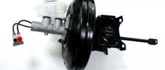
| 9 | Vacuum brake booster (VUT) |
| 10 | Brake pedal |
| 14 | Fluid pressure regulator in the TC of the rear wheels |
| 15 | Regulator knob |
GTZ and brake pedal
The main brake cylinder has not undergone any changes compared to previous Lada models like the VAZ-2110. It is attached to the vacuum brake booster and the force from the brake pedal is transmitted through the VUT.
On top there is a tank with two sections and with measuring notches to control the liquid level. A sensor located in the reservoir lights up an indicator on the dashboard when the brake fluid level drops.
Tubes extend from the GTZ to both circuits. It is due to the main cylinder that the fault tolerance of the entire structure increases. When the vacuum booster rod enters the cylinder and pushes the first piston, the primary circuit pressure increases and the brakes are applied. Due to the pressure, the second circuit also operates synchronously, providing uniform force on both axes.
Master brake cylinder
Since the car is front-wheel drive, the circuits are located diagonally, evenly distributing the force in case of failure of one of the circuits. For rear-wheel drive vehicles, the contours are divided into axles:
- first circuit – front axle;
- the second is the back.
The brake pedal is standard. The exact same one is installed on many Lada cars, there are no differences. It is attached directly to the vacuum booster.
The brake pedal article number is 1118-3504010. Price around 300 rubles;
GTZ article number – 1118-350501082. Costs about 1500-2000 rubles.
The vacuum brake booster, like power steering, is designed to reduce the amount of force applied. The driver of a car without VUT would have to press the brake pedal hard, reducing safety and driving comfort.
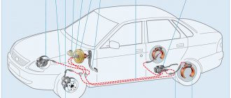
Design and purpose of components
The anti-lock braking system consists of three main components:
- Wheel speed sensors
- Control unit (module)
- Actuator
Car ABS elements
As noted, this system is often used as a basis for others. At the same time, the components of a number of other systems are only an addition to the ABS.
Sensors
Speed sensors are very important components, since the operation of the ABS system is based on their readings. Based on the pulses they supply, the control module calculates the rotation speed of each wheel, and based on the calculations, the actuator is controlled.
Location of the speed sensor on the wheel hub
The ABS design uses two types of sensors. The first ones are called passive sensors. These elements are of the inductive type.
Their design includes the sensor itself, consisting of a winding, a core and a magnet, as well as a gear ring used as a driving element. The ring gear is mounted on the hub, so it rotates with the wheel.
Inductive type sensor
The essence of the functioning of the passive element is very simple - the winding generates a magnetic field through which the gear ring passes. The existing teeth, when passing through the field, influence it, which ensures the excitation of voltage in the sensor. The alternation of teeth with cavities ensures the creation of voltage pulses, which make it possible to calculate the speed of rotation of the wheel.
A negative quality of passive sensors is the lack of measurement accuracy when driving at low speeds, which can cause the ABS system to not work correctly.
Now, due to the existing drawback, passive sensors are not used in the anti-lock braking system and have been replaced by so-called active elements.
As in the first option, active sensors consist of two main components - the sensor itself and the setting element. But in active elements, sensors are built either on the magnetoresistive effect or on the Hall effect. Both options require power supply to operate (the passive elements generated it themselves).
As for the driving element, the design uses a ring with magnetized sectors (multipole).
Design and principle of operation of an active speed sensor
The essence of the work of active elements is different. In the magnetoresistive version, a constantly changing field (from the master ring) leads to changes in the resistance readings in the sensor. In a Hall element, this field changes the voltage itself. In both cases, an impulse is created, from which the rotation speed can be calculated.
Active type elements have become widespread due to their high measurement accuracy at any speed.
Control block
The ABS system control module, like other ECUs involved in car systems, is needed to receive and process impulses transmitted from wheel sensors. It contains tabular data on the basis of which it controls the actuator. That is, after receiving a signal from each sensor, it compares it with the information entered in the table, and based on the results obtained, it will determine what it should do.
In a car with a number of systems based on ABS, the control unit has additional modules responsible for the operation of its systems.
Actuating mechanism
The actuator (also called a hydraulic unit or ABS module) is the most complex in design and consists of a number of elements:
- solenoid valves (inlet, outlet);
- pressure accumulators;
- return pump;
- shock-absorbing chamber.
ABS unit design
In the classic scheme, only one line goes to the brake operating mechanism, through which fluid is supplied from the master cylinder. In ABS, the return line is embedded into it, but it only passes inside the module.
What to do if the ABS light is on?
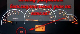
It is worth noting that the system works normally if the ABS icon lights up when the ignition is turned on and goes out after a couple of seconds. The first thing to do if the ABS light is constantly on is to check the fuse for this system, and also inspect the wheel sensors.
Quite often, the sensor connector on the hub either oxidizes or the wires fray. And if the ABS icon is on after replacing the pads or hub, then the first logical thought is that you forgot to connect the sensor connector . The presence of dirt on the sensor also causes the indicator to light up.
Quite often, car owners may be frightened by the appearance of an orange ABS icon after a good slip. In this case, you shouldn’t bother at all: brake sharply a couple of times and everything will go away on its own - the control unit’s normal reaction to such a situation. When the ABS light does not light up constantly , but periodically, then you need to inspect all the contacts, and most likely, the cause of the warning light can be quickly found and eliminated.
Generations and species
The modern system installed on a car is four-channel. It includes two valves for each wheel, as well as one pressure accumulator and shock-absorbing chamber per circuit (of which there are two).
In general, this system already has 5 generations. The first of them appeared in 1978, the second replaced it in 1980 and was installed until 1995, after which the 2nd generation replaced the 3rd. The modern 4th generation of the system appeared in 2003, and now the 5th generation is in use, which continues to be used to this day.
In terms of design features, the four-channel system is the latest and most technologically advanced. But it was preceded by:
- single-channel system (it used only two valves, which regulated the pressure in all lines simultaneously. It is noteworthy that in the single-channel type the system usually made adjustments only in the drive axle mechanisms, that is, the ABS worked only with two wheels);
- two-channel (in this type of ABS, the brake mechanisms are divided along the sides, each of which has its own set of valves. That is, one channel combines the mechanisms of the front and rear wheels of one side);
- Three-channel (it provided one set of valves for the wheels of the rear axle, and the front ones were each equipped with its own channel).
Nowadays, these three types of ABS systems are found only on older cars.
How to check using an oscilloscope and adapter
Testing with an oscilloscope allows you to more accurately test the sensor for functionality. The oscilloscope shows graphs of changes in the signal generated by the device. The sensor can supply pulses that comply with the standards, but the amplitude of the signal will be incorrect and will cause an ABS operation error. The test is performed on the car, without removing the sensor.
In order to check the ABS sensor with an oscilloscope, you must:
- Disconnect the sensor plug by analogy with the procedure used when measuring parameters with a tester.
- Connect an oscilloscope or oscilloscope to the sensor pins.
- Start rotating the hub through the wheel or other method at a frequency of 2-3 rpm.
- Record the signal oscillation curve.
- Carry out a similar procedure with the sensor located on the other side of the axis.
The serviceability of the sensor is indicated by:
- identical amplitude of oscillations of signals from sensors located on the left and right sides of the same axis;
- uniformity of the curve, without noticeable lateral deviations;
- amplitude stability in height, which should not exceed 0.5 volts.
Another way to measure parameters is to connect a laptop equipped with a special adapter. The device connects to a USB port and transmits signals to the corresponding software.
Sample USB Oscilloscope
The oscilloscope and adapter are highly specialized devices and are rarely used for personal use. The equipment is used in service stations.
Operating modes
The anti-lock braking system can operate in three modes:
- Pumping. In this mode, the brakes operate as usual. After pressing the pedal, the fluid goes to the mechanisms, the wheel slows down its rotation. In this mode, the inlet valve is open and the outlet valve is closed, that is, the liquid moves only along the supply line;
- Hold. If the unit calculates from the signals that one of the wheels is reducing rotation faster than the others, it will close the intake valve. As a result, the force of the mechanism will stop increasing, so the deceleration of the wheel stops at a certain level. On other mechanisms, the force will continue to increase;
- Pressure release. If, even after switching to the holding mode, the wheel still continues to slow down, the control unit activates the exhaust valve (closes the inlet valve) and part of the fluid goes into the pressure accumulator, thereby reducing the pressure in the mechanism (the wheel is released and begins to increase speed). As stated above, one battery is intended for two brake mechanisms (part of the circuit). There are situations when the pressure is released from both of these mechanisms at once, so the volume of the battery may simply not be enough. And then the pump starts working, pumping the excess into the main line.
ABS system diagram
During braking, the system changes its operating mode many times, which ensures effective braking. At the same time, the driver does not need to “play” with the pedal to prevent wheel locking; the system does everything itself.
Troubleshooting methods
Now that all the causes have been identified, we can begin to consider troubleshooting. But, before we begin, it is worth noting that a car enthusiast needs to have an idea of the design features of the engine if he wants to fix the problem himself. Otherwise, go directly to a car service center, in order to avoid other problems that, due to lack of experience, car enthusiasts usually create for themselves.
Sensors
Often, the reason why the check light on Kalina may come on is the failure of one of the sensors. Possible ones that are worth checking right away include: mass air flow sensor, idle speed control, crankshaft position sensor, oxygen sensor and coolant temperature sensor.
You can determine the cause by going through each sensor separately and using a tester to check their functionality.
But, there is a simpler and more effective way to determine the malfunction of a particular sensor, namely connecting to the electronic engine control unit. Here you can look at the errors and, by deciphering them, determine where the problem is.
Throttle
A clogged throttle valve can often cause the check engine light to come on because not enough air is supplied to the power unit. The solution to the problem is cleaning. This process can be carried out using carburetor cleaning fluid or VD-40 fluid.
The part is removed from the car and cleaned, after which it is installed in place. It is also recommended to check the throttle position sensor, which may have failed.
Injectors
One of the common reasons for the “check” icon to appear on the dashboard is a malfunction of one or more injectors that do not spray the fuel mixture properly. So, it is worth dismantling all the elements and checking them using a special stand.
If there is none, then you can use the traditional method by pouring flushing fluid into the fuel supply pipes and activating the injectors using the battery. This way it will be clear which injector is not working well. But, experienced auto mechanics recommend cleaning and checking the nozzles on a stand, since the effectiveness of the procedure is higher.
Fuel pump and filter
Another cause of the malfunction may be a malfunction of the gasoline pump or its filter. Lack of power or contamination of the filter elements leads to the fact that an insufficient amount of fuel will enter the power unit to form an air-fuel mixture.
This can also cause such a well-known automotive effect as engine tripping.
The malfunction can be cured by checking the functionality of the gasoline pump, as well as by replacing the filter inside the gasoline pump. It is also worth looking at the fuel filter, which could become clogged when pouring low-quality gasoline.
Air filter
A clogged air filter can cause insufficient air in the combustion chambers. So, to check this element, it must be dismantled, which is done quite simply. By inspecting the filter element, you can find out how dirty it is and whether the product needs to be replaced. So, after replacement, the check signal from the dashboard may disappear.
Spark plugs and high voltage wires
Wiring is also often the reason why the check icon lights up on the panel. This happens when the spark plug is inoperative or there is a breakdown in one of the high-voltage wires.
It is recommended to check spark plugs on a special spark plug stand. But, if there is none, then you can use the generally accepted “old-fashioned” methods. But high-voltage wires are checked using a conventional multimeter, where the resistance along each wire should be about 5 ohms. If a broken part is found, it must be replaced.
Petrol
But, in addition to the above reasons, the problem may lie on the surface. Thus, ordinary low-quality gasoline can cause the “Check Engine” icon to appear on the car’s dashboard. To eliminate the breakdown, it is necessary to drain the low-quality fuel and flush the fuel supply system. But, if you drive for a long time on such fuel, the batteries may fail, which should also be checked when flushing.
Advantages and disadvantages
Other advantages of this system also include:
- maintaining the trajectory of movement during braking when entering a turn;
- maneuvering is allowed when braking;
- convenience for novice drivers.
But ABS is not perfect. Under certain conditions, this system may not function correctly and may make errors. And this affects the effectiveness of braking and can somewhat disorient the driver.
These conditions are:
- road with problematic surface;
- sand;
- ice;
- surface with bumps, “comb”.
In general, ABS works great only on a flat road with good wheel grip. In other cases, the ABS system may make errors.
For example, on a problematic highway with frequently alternating surfaces (the asphalt alternates with crushed stone or other bulk material), the system will not be able to select the optimal force on the mechanisms, which is why the braking distance increases.
When flying off the road, ABS is also not a “helper”. Here, blocking is the best way to stop the car as quickly as possible.
The peculiarities of the anti-lock braking system also include some delay in activation when driving at high speeds (over 130 km/h). It’s just that under such conditions the control unit needs some time to make calculations and engage the valve body.
At low speeds (10-15 km/h), the system turns off completely. If this is a stop on a flat surface, then turning off the ABS has no effect, but when braking on a descent, deactivating the system can have a negative impact.
Note that disabling ABS is a relative concept, since the system operates constantly and cannot be turned off. Here, deactivation should be understood as a transition to “standby mode”. That is, it is activated again and will begin to perform its function the next time you press the brake pedal. The only time it won’t turn on is when braking when driving at low speeds.
Why does the ABS light even come on?
In a normally running vehicle, this indicator shows you that the wheels have been unlocked. In this case, everything works fine, the sensors sensed the need to turn on the safety system, initiated its operation and demonstrated to the driver that some assistance was provided when braking. When you see the ABS light on while braking, it is better to release the brake pedal a little and take over control of the car. If you have an expensive, high-tech car, you can trust the well-thought-out systems and let ABS+EBD do the job. In other cases, the light may be on for the following reasons:
- the sensors are clogged, the on-board computer indicates that the diagnostic error code should be read;
- Dirt or rust got on the sensors, which caused the anti-lock braking system to turn on incorrectly;
- there is a problem in the on-board electrical system, which is demonstrated by random lights coming on;
- the wheel bearing has failed, which forces the sensors to constantly turn on the anti-lock braking system by mistake;
- the fuses in the unit responsible for the ABS system have failed and are passing the signal directly;
- There was an error in the computer that caused the ABS light to come on.
Also, sometimes troubles occur with the generator and other elements of the machine’s electrical circuit, which can result in the lighting of the diagnostic system light or warning lights of any type. For example, on a Volkswagen car produced in the 2000s, the anti-lock braking system light comes on even if there is an error in completely different components. Therefore, self-diagnosis is only a partially acceptable method of solving the problem, because often the driver does not have special tools at hand for a good investigation.
Improvements and improvements
Engineers have brought the ABS design to a high level and there is practically nothing to improve. Only some components are subject to modifications. Thus, wheel sensors now not only measure rotation speed, they additionally integrate G-sensors and accelerometers.
Improvements also include increasing the functionality of the electronic unit (that is, the use of ABS as a basis for other systems). For example, the ABS control unit is used in the traction control system and brake force distribution.
Let's sum it up
There are many breakdowns that can affect the ABS system. But the most common type of malfunction is sensor failure. If your car's anti-lock braking system is showing problems, the first thing you should do is check the sensors. There are several methods for testing the correct operation of these parts, so you can choose the most convenient testing option. However, diagnostics alone will not help the matter; any problems that have arisen will have to be corrected.
Today you can find and purchase ABS sensors from any manufacturer. You can find both simple parts for replacing factory sensors and original system elements at very affordable prices. And selection in this case will play a very important role. Use the factory catalogs to select sensors that are completely suitable for your vehicle and match the functions of the ABS system. To ensure that the anti-lock braking system does not interfere with the quality operation of the car, but helps to perform important tasks when braking, monitor the serviceability of the sensors and carry out diagnostic and repair work in a timely manner. Moreover, you can change the sensors of this system yourself. How often does ABS show problems in your car?
Dear customers, in order to avoid errors when sending a rear wheel ABS (speed) sensor, induction 1118-3538370 / 0265007886, in the “Comment” line indicate the front or rear ABS sensor, your car model, year of manufacture.
The main task of ABS is to maintain the stability and controllability of the Lada Kalina, Kalina 2, Priora, Priora 2, Granta when braking. By limiting wheel slip, ABS allows you to maintain vehicle controllability. The Electronic Brake Force Distribution (EBD) function is an extension of the ABS functions and is designed to optimally implement the vehicle's braking properties depending on its load and braking mode.
- Front right wheel speed sensor;
- Rear right wheel speed sensor 1118-3538370 / 0265007886;
- Rear left wheel speed sensor 1118-3538370 / 0265007886;
- Front left wheel speed sensor;
- The hydraulic unit is assembled with the control unit.
ABS repair — Lada Priora Hatchback, 1.6 l., 2008 on DRIVE2
So I continued to look for the cause of the ABS malfunction. To begin with, I decided to make an appointment with the officials and carry out diagnostics. Moreover, I also got involved in a promotion where the entire car was shaken up for just 640 rubles. They ordered both front sensors to be replaced. Another problem was immediately discovered that was not related to my visit to the service. The right CV joint boot is torn. Since I crawled under the car a couple of days ago and everything was intact, and the tear looked fresh and clean, we decided to make do with replacing only the boot itself. Satisfied with the timely repair and diagnostics, which put everything in its place, I went home.
Then the search began for these same sensors. I was still haunted by the thought of whether it was possible to bring him to his senses. It’s just strange that a sensor of this type broke down, and on both wheels. I googled, read brilliant manuscripts on how to restore sensors, of course, according to reviews, they are not durable, but once again I climbed in the wheel arch in search of a hidden break or wear, and re-measured their contacts with new ones. A break and that's it. So the restoration plans failed. I started looking for new sensors. The price tag generally varies from 1400 to 1600 kopecks, which is somehow not at all budget for this car. The cheapest thing we could find was from the same officials for 1200 and in another store, the officials will deliver it only by the middle of the month. So I decided to buy it from the store.
I drove it, took it, well, I think you’ll make money from me in a minute. I was too lazy to change it myself because the weather is complete trash with snowfall, and it’s well known how these sensors get damaged. So I decided to entrust this disgrace to trained people. I went to the service. As it turned out, it won’t be easy for them to change these sensors either. Plus, it turned out that on both wheels the mounting brackets for these same sensors were bent, as a result of which they rubbed against the comb and stopped showing signs of life. I had to remove the calipers and brake discs in order to get to the bracket bolts. When removing it, it turned out that the left caliper bracket was held in place by one bolt, and the second was simply in place, but there was no thread there. So I splurged another 600 rubles for the bracket and 600 for the brackets. Well, here’s a photo of the removed brackets and sensors.
Well, after that, of course, everything came together perfectly. Upon startup, the ABS fault icon immediately went out and the brakes started working as they should.
Issue price: 4,000 ₽
www.drive2.ru
Why did it happen so?
Perhaps the automatic requests do not belong to you, but to another user accessing the network from the same IP address as you. You need to enter the characters into the form once, after which we will remember you and be able to distinguish you from other users exiting from this IP. In this case, the page with the captcha will not bother you for quite a long time.
You may have add-ons installed in your browser that can make automatic search requests. In this case, we recommend that you disable them.
It is also possible that your computer is infected with a virus program that is using it to collect information. Maybe you should check your system for viruses.
If you have any problems or would like our support team, please use the feedback form.
Even children probably know what ABS (Anti-lock Braking System) is. This system allows you to perform the most effective braking to stop the vehicle as quickly as possible. The system is electronic and is equipped with many sensors and a control unit, which ensures that the wheels do not lock during braking, that is, “do not skid.” Such an invention saves hundreds or maybe even thousands of lives on the road every day. The ABS system prevents skidding and loss of control, which is very important on slippery roads, as well as in case of emergency braking.
In this article, I will tell you how to check the ABS sensor if it malfunctions, as well as if an emergency indicator appears on the dashboard in the form of three English letters “ABS”. You will learn how to test the ABS sensor at home in various ways using a multimeter.
The most common breakdown in the ABS system is a circuit break, when communication is lost between the control unit and the sensor. This can happen for various reasons, which you will learn about a little later.
Choosing rear brake pads for Lada Largus
The rear pads on the Lada Largus with 8 valves have dimensions of 203x38 mm, Largus with a 16-valve engine is equipped with pads with dimensions of 228x42 mm.
| Manufacturer | engine's type | vendor code | approximate price |
| ORIGINAL | |||
| RENAULT (France) | 8V | 440601749R, 7701208111 | 2400 rub. |
| 16V | 7701210109 | 3000 rub. | |
| LADA (Russia) without ABS | 8V | 7701208111 | 2100 rub. |
| 16V | 7701210109 | 2500 rub. | |
| ANALOGUES | |||
| BOSCH (Germany) | 8V | 986487585 | 1300 rub. |
| 16V | 986487754 | 1800 rub. | |
| TRW (Germany) | 8V | GS8729 | 1700 rub. |
| 16V | GS8780 | 2000 rub. | |
| FERODO (Switzerland) | 8V | FSB519 | 1500 rub. |
| 16V | FSB4031 | 1600 rub. | |
| BREMBO (Italy) | 8V | S 61 520 | 1300 rub. |
| 16V | S 68 546 | 1900 rub. |
For safe operation of the machine, all pads on one axle should be replaced, regardless of the reason for the repair.
ABS installation
First you need to put the car on a jack and remove the wheel. Next, unscrew the caliper mounting bolts using the appropriate wrench. Use a screwdriver to press out the caliper and remove it. To prevent brake fluid leakage, the brake hose must be clamped. Next, the caliper fitting is disconnected and a new one is installed in its place, with new brake pads (you need to select them carefully - you need a model that has a seat for the ABS sensor). After this, the ABS sensor itself is installed. It is important not to confuse the sensors of the front and rear wheels; they have design differences.
Let's move on to replacing the CV joint. First you need to turn the wheel in the direction from which you plan to replace the part. The locknut is unscrewed (during assembly it must be replaced with a new one). The ball joint is unscrewed from the steering knuckle.
Using a drift or a special puller, the CV joint spline is knocked out of its seat and then removed from the drive shaft. When installing a new CV joint, it is better to change the boot along with it. In this case, it is necessary to treat the surface under the boot with lithol.
When starting to install the hydraulic modulator, you need to remove the negative terminal from the battery. Next, remove the modulator cover and disconnect the electrical connectors. Carefully disconnect the brake pipes to prevent fluid from draining and finally remove the modulator. A new ABS control unit is installed in conjunction with the new hydraulic modulator. After this, two additional relays are installed (installation locations depend on the specific car model). The brake pipes and electrical wiring are connected.
ABS installation complete! The brakes must be bled before use.
DIY sensor repair
After diagnostics and detection of a faulty element, the device must be dismantled for further repairs. The process of removing it is similar to the first stage of replacing the ABS sensor and is not particularly difficult.
How to fix: step-by-step instructions
Having finished dismantling the device, we proceed to repair work:
- We disassemble the sensor, cutting off with a hacksaw the part of it containing the measuring coil inside. Carefully saw through the body of the device in a circle, trying not to damage the fasteners.
Carefully separate the part with the fastener
This sensor element will be the subject of repair work.
In order to rewind the damaged wire, you need to remove the coil casing. The reel is completely cleared of old wire
The number of turns of the wire must be controlled by measuring the resistance
The copper winding of the coil must be carefully insulated
The capacitor shell can be used to fill the new coil housing.
This is what a new sensor housing made of epoxy glue looks like
The sensor mount can be glued to the part with quick-drying glue
The device is ready for installation on the seat
The repair of the sensor is completed, you can mount it on the hub, grinding the new housing with sandpaper for a better fit to the mounting socket. When installing a repaired device, be sure to comply with the following conditions:
- We position the sensor core parallel to the teeth of the response disk, making sure that it does not overlap two adjacent teeth.
- Leave a gap between the tooth and the core of 0.9–1.1 mm.
The final stage of repairing any of the ABS elements is to check the functionality of the system. We perform it by starting the car engine and making sure that the controller on the dashboard goes out 3-5 seconds after the start.
Note that some sensors produced by the foreign auto industry can be disassembled without fundamentally compromising the integrity of the structure - the upper shell of the part can be removed by pre-heating it with a hair dryer or a blowtorch. An example of repairing such a device is presented in the video.
ABS fault codes (ABS error codes)
| Code | Code Description |
| S0035 | Front left DSC circuit failure or unreliable signal |
| C0040 | Failure in the front right DSC circuit or unreliable signal |
| C0045 | Failure in the rear left DSC circuit or unreliable signal |
| C0050 | Failure in the rear right DSC circuit or unreliable signal |
| S0060 | Failure in the exhaust circuit of the front left EMC |
| C0065 | Failure in the intake front left EMC circuit |
| S0070 | Failure in the exhaust circuit of the front right EMC |
| S0075 | Failure in the intake circuit of the front right EMC |
| C0080 | Failure in the exhaust circuit of the rear left EMC |
| S0085 | Failure in the intake rear left EMC circuit |
| C0090 | Failure in the exhaust circuit of the rear right EMC |
| S0095 | Failure in the intake rear right EMC circuit |
| C0110 | Failure in the EWH circuit |
| C0121 | Failure in the EMC power supply voltage relay circuit |
| C0161 | Brake light switch circuit failure |
| C0245 | Error when measuring DSC frequency |
| C0550 | Internal ECU fault |
| S0800 | Supply voltage is below or above operating range |
In case of malfunction with code C0035, C0040, C0045 and C0050, it is necessary to check the electrical circuit to the corresponding DSC for a short circuit or open circuit, as well as the supply voltage of this DSC.
In case of a malfunction with code C0110, it is necessary to check the supply voltage at the contact of the second block of the harness to the hydraulic unit. For code C0121, check the supply voltage at the contact of the third block of the harness to the hydraulic unit.
If there is a malfunction with code C0161, check the electrical circuit to the brake light switch for a short or open circuit.
At contact 20 of the harness block to the hydraulic unit there should be: - low-level input voltage no more than 0.3 U power; — high level input voltage of at least 0.8 U supply.
If there is a malfunction with code C0245, it is necessary to check the fastening of the DSC and the gaps between the DSC and the rotor. Gap dimensions: between the front wheel speed sensor and the teeth of its rotor should be 0.45-1.55 mm; between the rear wheel speed sensor and its rotor is 0.2-2.3 mm.
Common breakdowns
A slight cracking sound when pressing on the brake pedal is quite normal. This sound occurs due to the functioning of modulators. If the ABS is faulty, its indicator lights up and does not go out even when the engine is running. There are several most common malfunctions of the anti-lock braking system:
- Deactivation based on self-diagnosis results. This may be caused by a malfunction of the control unit or damage to the ABS touch sensor wiring.
- After activation, ABS self-diagnoses, but then turns off. This problem can be caused by broken wires, broken contacts or their oxidation, where the supply of power and signals is disrupted.
- An error appears, but the ABC sensor works. This is a consequence of a break in the touch sensor. It can also be caused by differences in tire pressure or even different tread patterns.
- Complete loss of system functionality. There can be a lot of reasons for this, ranging from sensor breakdowns to wear of the wheel bearings.
To identify a malfunction, you need to check the pressure and play in the tires, the performance of the comb and rotor. If the elements have chips, then it is better to completely replace them. If the problem remains unresolved, then the reason most likely lies in the electronic component. In this case, you need to get a diagnostic code.