The lubrication system of a car engine or the engine lubrication system (ELS) is a set of car mechanisms that are involved in reducing friction between the mating parts of the internal combustion engine, minimizing the power consumption of the internal combustion engine on friction. The operating principle of the engine lubrication system is to ensure the supply of lubricants (engine oil) to all rubbing parts of the internal combustion engine in all operating modes. The SSD works cyclically. An oil film forms between two surfaces of moving bodies. It separates moving surfaces and protects rubbing surfaces from additional loads.
General device
The engine lubrication system includes:
- oil pan with oil intake
- oil pump
- oil radiator
- oil filter
- connecting highways and channels
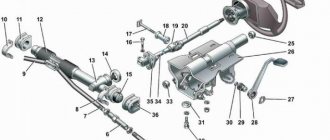
Rice. Engine lubrication system diagram: 1 - oil pan; 2 — oil level and temperature sensor; 3 - oil pump; 4 - pressure reducing valve; 5 — oil radiator; 6 — oil filter; 7 - bypass valve; 8 - check valve; 9 — oil pressure sensor; 10 - crankshaft; 11 — nozzles; 12 — exhaust camshaft; 13 — intake camshaft; 14 - vacuum pump; 15 — turbocharger; 16 — oil drainage; 17 - mesh filter; 18 - throttle.
The purpose of the engine oil pan is to store oil. You can check the oil level in the pan using a dipstick, as well as an oil level and temperature sensor.
The oil pump is used to pump oil into the system. It is driven by a crankshaft, camshaft or auxiliary drive shaft. The most common are gear type oil pumps.
Rice. Single-section gear oil pump with built-in pressure reducing valve: 1 - inlet cavity; 2 - discharge cavity; 3 - pressure reducing valve
The oil is cleaned from carbon deposits and wear by an oil filter . Cleaning the engine oil is achieved by a filter element, which is recommended to be replaced simultaneously with an oil change.
Cooling and heating of engine oil is carried out by an oil cooler . The oil cooler circulates coolant, which heats the oil when the engine is cold and cools it when the engine is hot. The engine oil must have a temperature above 100°C in order for residual water to evaporate from it, but its temperature should not exceed the limit in the range from 138°C to 148°C.
The oil pressure in the system is monitored by sensors installed in the oil line. The sensor sends a signal to a lamp on the dashboard. Pressure information can also be sent to the engine management system. If the pressure drops above normal, the control system must stop the engine.
Modern engines may have oil level and temperature sensors. The information they receive is also displayed on the dashboard.
Constant operating pressure in the lubrication system is maintained using one or more pressure-reducing (bypass) valves, which are installed in the oil pump and filter.
Two Stage Oil Pumps
Let's consider the design of a two-stage oil pump using the example of a rotary-type unit from the VAG automaker.
- The first stage of operation is determined by the designers, based on the volume of oil required by the engine in all operating modes. From the injection cavity, oil is directed into the engine channels and to the movable rotor where it rests on the adjusting plate. In this mode, the volume of the suction cavity and, as a result, the amount of pumped oil is small.
- Second stage. As engine speed increases, the need for more lubricant arises. The pressure on the moving rotor weakens. Now the adjusting spring rotates the stator a few degrees, changing the position of the driven rotor. This increases the volume of the suction cavity and the amount of lubricant pumped.
In FSI Audi engines of 2.8 and 3.2 liters, the transition from the first to the second stage occurs at crankshaft speeds above 4600. Thanks to two-stage pumps, the designers managed to reduce fuel consumption by 1/3.
Operating principle of the engine lubrication system
The most common engine lubrication system currently is combined . In such a system, some parts are lubricated under pressure, while others are lubricated by gravity or splashing.
The engine is lubricated cyclically. After it is started, oil is pumped into the system by the oil pump. The pump creates the necessary pressure and supplies oil to the oil filter, where it is cleaned from mechanical impurities. Next, the oil is supplied through the channels to:
- crankshaft connecting rod journals
- crankshaft journals
- camshaft bearings
- upper connecting rod support for lubrication of the piston pin
Oil comes to the working surface of the cylinder from holes in the lower connecting rod support or from special nozzles.
Other parts of the engine are splash lubricated, i.e. Some of the oil leaking from the gaps in the joints is sprayed onto the moving parts of the crankshaft and timing gear. When oil splashes, an oil mist is created, which, as it settles, lubricates the engine parts.
The oil drains into the engine sump under the influence of gravity, after which the lubrication cycle is repeated.
Also, some vehicles use a dry sump lubrication system . In such a system, the main supply of oil is contained in an independent oil tank, from where it is supplied to the main oil line of the engine by the pressure section of the oil pump. Such systems ensure an uninterrupted supply of oil to the rubbing parts of the engine on long steep climbs, descents and rolls without any oil starvation and oil leaks through the crankshaft oil seals. In addition, the use of a dry sump system makes it possible to reduce engine height, reduce oil consumption and maintain its physical and chemical properties for a longer period due to the ability to remove crankcase gases from the oil.
Rice. Typical diagram of the lubrication system of a dry sump engine: 1 - oil centrifuge; 2 - engine; 3 - full-flow coarse filter; 4 — oil radiator; 5 - bypass valve; 6 — oil tank; 7 - coil for heating oil; 8 — pre-start oil pump; 9 — oil-pressure strainer; 10, 11 - injection and pump-out sections of the main oil pump
Purpose of SS car engine
An internal combustion engine is a complex complex of components and assemblies connected into a single whole and ensuring stable operation of the power unit. But since it contains many parts that rub at high speed, for their smooth functioning it is necessary to ensure reliable delivery of lubricant. This is what the lubrication system does: without it, the engine would not last even ten minutes. Running the power unit “dry” is fraught with rapid heating of the rubbing surfaces to a critical level, after which, due to thermal expansion, the gaps decrease, followed by destruction of engine parts subject to increased friction.
The difficulty in implementing an engine lubrication system is not only to ensure that the lubricant is delivered to the right place, although this is also a difficult engineering task, but also to ensure the circulation of engine oil in a closed cycle with minimal losses.
Here is a list of tasks solved through the use of SS:
- reduction of friction force due to the formation of a thin protective film on rubbing surfaces;
- cooling the surfaces of power unit parts;
- cleaning technical fluids from metal shavings and other solid contaminants on protected surfaces;
- ensuring uninterrupted circulation of lubricating fluid under the required pressure;
- preventing premature wear of SA parts.
VAZ engine lubrication system
The VAZ engine lubrication system is combined, i.e. lubrication occurs simultaneously in two ways: under pressure and splashing. At an oil temperature of 85 °C and a crankshaft rotation speed of 5600 rpm, the pressure in the lubrication system is from 3.5 to 4.5 kgf/cm2. At the minimum crankshaft speed (from 850 to 900 min-1), the minimum pressure should be at least 0.5 kgf/cm2. The capacity of the lubrication system, including oil in the oil filter, is 3.75 liters.
Rice. Diagram of the VAZ engine lubrication system: 1 - oil pump; 2 — oil sump: 3 — oil supply channel from the pump to the filter; 4 - horizontal channel for supplying oil from the filter to the oil line; 5 — channel for supplying oil to the drive gear of the oil pump and ignition distributor; 6 — channel in the crankshaft journal; 7 — front crankshaft oil seal; 8 — oil supply channel from the oil line to the main bearing and to the drive shaft of the oil pump and ignition distributor; 9 — gear drive of the oil pump and ignition distributor; 10 — drive shaft of the oil pump and ignition distributor; 11 — channel for oil drain; 12 — channel in the camshaft cam; 13 - main channel in the camshaft; 14 — channel in the crankshaft support journal; 15 - annular groove on the middle support journal of the camshaft; 16 — oil filler cap; 17 — inclined channel from the cylinder head; 18 — vertical channel in the cylinder block; 19 — oil line; 20 — pressure sensors and oil pressure warning lamp; 21 — oil supply channel to the main bearing; 22 — oil supply channel from the main bearing to the connecting rod; 23 — oil level indicator; 24 — oil filter; 25 — oil filter bypass valve; 26 - anti-drainage valve
We consider the VAZ engine lubrication system in more detail in the next article.
Wet sump
This method is considered commonly used due to the ease of its implementation. Structurally, a wet sump lubrication system consists of the following components:
- oil pan;
- oil pump;
- oil pickup device;
- pressure reducing valve;
- oil lines;
- fine/coarse filters MM;
- radiator;
- lubricant level and pressure sensors;
- oil filler neck.
When the power unit is running, the oil pump pumps liquid under pressure into the FGO through the mesh of the oil receiving device, from where it is directed to the central oil line located in the cylinder block. From here, under pressure, through the channels in the BC partitions, the oil enters the crankshaft, lubricating first the main bearings, and then the connecting rod bearings. Excess lubricant is squeezed out through the technological gaps and, falling on the rotating parts of the crankshaft, is sprayed throughout the entire volume of the engine, lubricating the piston pins, internal surfaces of the cylinders, and other engine parts by gravity. In parallel, the MM is supplied through an oil pipeline to the camshaft, lubricating its bearings, gears and valve rocker axles. A small part of the lubricant (no more than 20% of the total volume circulating in the system) enters the fine filter, from where, once cleaned, it goes back to the sump
Possible problems with the system and how to resolve them
Some engine problems in the lubrication system may occur unexpectedly, even if you recently repaired the car or carried out its maintenance. Let's list the main problems and look at ways to solve them:
| Type of malfunction | Cause | Elimination |
| The oil pressure sensor does not light up when the ignition is turned on. | 1. The indicator is burnt out | 1. Replace the gauge bulb in the dashboard |
| 2. Damage to the wire, oxidation of the connector | 2. Inspect the connection and, if necessary, replace the wire | |
| 3. Failure of the oil pressure sensor | 3. Replace the sensor with a new one | |
| The oil pressure indicator lights up at idle and turns off when the speed increases. | Low oil pressure due to overheating. The cooling system is not working properly | “Drive” the car at high speeds for 15-20 minutes to cool the engine; Carry out a diagnostic inspection of the cooling system performance |
| The indicator on the dashboard lights up at increased engine speeds | Reducing valve faulty | Using a dipstick, check the engine oil level in the car and, if necessary, replace the pressure relief valve |
| The indicator is constantly on | 1. Too low amount of oil fluid | 1. Check the oil level and add if necessary |
| 2. The pump does not work, the oil pump channel is dirty | 2. Clean or replace the pump | |
| High oil consumption | Wear of cylinders, piston rings, valve stem seals, sealing elements | Inspect the engine system and eliminate the cause of the leak. |
And finally
The engine lubrication system protects the vehicle from daily overheating and significantly increases its service life.
Therefore, it is important to keep it in good condition. To do this, the driver must carry out timely maintenance of the vehicle and eliminate minor faults, which in the future can lead to expensive repairs.
System oil level
Under no circumstances should the oil be allowed to exceed a certain specified level in the oil pan, as this can lead to various malfunctions and breakdowns, in particular failure of the pumping unit. For this purpose, there is a separate element called the oil dipstick.
There are two marks on it, one is responsible for the minimum oil in the pan, the other is for the permissible maximum that the system allows to contain. Naturally, an intermediate indicator is considered optimal. If the oil fluid is at the lower level, the parts are not sufficiently lubricated; if at the upper level, the system quickly becomes dirty, and the consumption of liquids, including fuel, increases.
MAIN FAULTS
The design of the oil pump, no matter what type it is, is relatively simple, which ensures its reliability and long service life. And yet it does have faults, or rather there is only one – a decrease in productivity, which leads to a drop in pressure in the system. And this can lead to more serious damage, since components that are not sufficiently lubricated begin to wear out intensively due to oil starvation. This can happen for various reasons.
- The first of these does not apply to the pump, but leads to negative consequences in its operation - clogging of the oil receiver mesh with wear products and dirt. As a result, insufficient oil flows to the pump. It is not difficult to fix such a malfunction - just remove the pan and oil receiver, then thoroughly clean and rinse the mesh.
- The problem with pressure drop can occur due to wear of the pump components or prolonged operation with oil that contains a large number of contaminants. The result of this is the formation and increase of gaps between pump parts. Because of this, the lubricant simply flows through these gaps inside the injection cavity and the gears or rotors are not able to capture it in order to pump it into the line. In most cases, the performance of the lubrication system is restored by replacing worn elements or the assembly as a whole.
- The bypass valve can also create problems. Due to dirt, it can jam in the open position, and oil will constantly flow into the pan. This malfunction can be eliminated by disassembling and washing the pump and its channels.
Question 37 General structure and principle of operation of a four-stroke internal combustion engine.
The engine consists of a cylinder 5 and a crankcase 6, which is covered from below by a pan 9 (Fig. a). A piston 4 with compression (sealing) rings 2 moves inside the cylinder, having the shape of a glass with a bottom in the upper part. The piston, through piston pin 3 and connecting rod 14, is connected to the crankshaft 8, which rotates in the main bearings located in the crankcase. The crankshaft consists of main journals 13, cheeks 10 and a connecting rod journal 11. The cylinder, piston, connecting rod and crankshaft make up the so-called crank mechanism, which converts the reciprocating movement of the piston into the rotational movement of the crankshaft
. The position of the piston in the cylinder at which its distance from the axis of the engine shaft reaches a maximum is called top dead center (TDC). Bottom dead center (BDC) is the position of the piston in the cylinder at which its distance from the axis of the engine shaft reaches a minimum.
. The volume of the cylinder formed by the piston when it moves between dead points is called the working volume of the cylinder Vh.
Figure 1.2 . Diagram of a piston internal combustion engine
Engine displacement is the product of the cylinder displacement times the number of cylinders.
The ratio of the total volume of the cylinder Va to the volume of the combustion chamber Vc is called the compression ratio
The operating cycle is a set of sequential processes carried out to convert the thermal energy of fuel into mechanical energy.
A)
b)
Rice. 1.3. Engine duty cycle diagrams
Operating cycle of a four-stroke internal combustion engine
An engine whose operating cycle is completed in four strokes, or two revolutions of the crankshaft, is called four-stroke. The operating cycle in such an engine occurs as follows. The working cycle of a 4-stroke carburetor internal combustion engine is completed in 4 piston strokes (stroke), i.e. in 2 revolutions of the crankshaft. During the 1st stroke - intake, the piston moves from top dead center (TDC) to bottom dead center (BDC). The intake valve is open and the combustible mixture from the carburetor enters the cylinder. During the 2nd stroke - compression, when the piston moves from n. m. t. sq. m.t., the inlet and outlet valves are closed and the mixture is compressed to a pressure of 0.8-2 MN/m2 (8-20 kgf/cm2). the temperature of the mixture at the end of compression is 200–400°C. At the end of compression, the mixture is ignited by an electric spark and fuel combustion occurs. Combustion takes place when the piston position is close to c. mt. At the end of combustion, the pressure in the cylinder is 3-6 Mn/m2 (30-60 kgf/1cm2), and the temperature is 1600-2200°C. The 3rd stroke of the cycle—combustion and expansion—is called the power stroke; During this stroke, the heat obtained from fuel combustion is converted into mechanical work. 4th stroke - release occurs when the piston moves from N. m. t. to v. m.t. with the outlet valve open. The exhaust gases are displaced by the piston.
Working process of four stroke diesel engine
includes the following steps:
1. Intake stroke. When the piston moves, a vacuum is formed in the cylinder and atmospheric air enters its cavity through the air filter. In this case, the inlet valve is open.
2. Compression stroke. The piston moves, compressing the incoming air. For reliable ignition of fuel, it is necessary that the temperature of the compressed air be higher than the auto-ignition temperature of the fuel. The intake and exhaust valves are closed.
3. Expansion stroke (or power stroke). The fuel injected at the end of the compression stroke, mixed with heated air, ignites, and the combustion process begins with a rapid increase in temperature and pressure. At this moment both valves are closed. Under the influence of gas pressure, the piston moves, thereby performing useful work.
4. Release stroke. The piston moves upward, pushing exhaust gases into the exhaust manifold, the temperature of which decreases.
Rice. 1.4. Inlet Fig. 1.5. Compression
Rice. 1.6. Expansion Fig. 1.7. Release
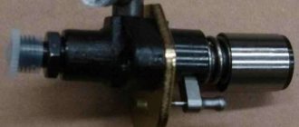
Valve N428
The oil pump control valve N428 is designed to regulate the pressure on the control piston. Depending on the pressure on the piston, the position of the stator and the volume of the suction chamber changes. Part of the oil from the discharge cavity is always supplied to the control line to valve N428. At the command of the engine control unit, power is supplied to the valve and oil is supplied to the control piston. By design, the N428 is an electrically controlled hydraulic 3/2 way valve.