Description of the steering design
The steering is rack-and-pinion type, with a propeller shaft and a tilt-adjustable steering column.
The steering wheel is mounted on the splines of the steering shaft and secured with a self-locking nut.
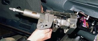
The steering shaft is composite, consisting of an upper and intermediate shaft connected by a universal joint. The upper shaft rotates in two bearings pressed into the steering column tube. An ignition switch with an anti-theft device is installed on the top of the column pipe.
The steering column bracket is attached to the body with two bolts and two nuts. The bolts are special, with break-off heads. When these bolts are tightened, their heads break off.
Steering:
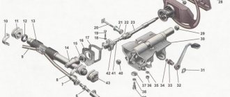
1 - sealing ring; 2 — protective cover for the tie rod end; 3 - spring ring; 4 — ball pin; 5 — tie rod end; 6 — rod coupling with locknuts; 7 — steering rod; 8, 10 — steering gear mounting brackets; 9 — steering rod; 11 — right steering gear support; 12 — protective cover of the steering mechanism; 13 — steering mechanism; 14 - seal; 15 — protective cap; 16 — coupling bolt of the elastic coupling flange; 17 — coupling bolt of the steering column fixing mechanism; 18 — spacer sleeve; 19 — universal joint; 20 — upper steering shaft; 21 — steering wheel; 22 — steering wheel fastening nut; 23 — steering wheel pad; 24 — decorative insert of the lining; 25, 33 — steering shaft bearings; 26 — bracket for fastening the steering column to the body; 27 — retaining ring; 28 — steering column fixation lever; 29 — adjusting sleeve; 30 — washers; 31 — fixing plate; 32 — bolt with a tear-off head; 34 — intermediate steering shaft; 35 — rubber elastic coupling; 36 — left steering gear support
The bracket is pivotally connected to the steering column tube and is equipped with a steering column fixation mechanism. By moving the locking lever to the lower position, you can change the angle of the steering column. When the lever is raised, the column is fixed in the selected position.
The steering shaft is connected to the steering mechanism through a rubber elastic coupling.
The steering mechanism consists of a crankcase, a drive gear and a rack in gearing. The mechanism is secured to the partition of the engine compartment with two brackets on rubber supports. When the steering wheel is turned, rotation is transmitted through the upper and intermediate shafts of the steering column to the drive gear, which, when turning, moves the rack.
Steering rods are bolted to the steering rack, which consist of the rods themselves, tips and couplings with locknuts. At the inner ends of the steering rods there are eyes with rubber-metal bushings pressed into them. Ball pins are installed in the outer rod ends, with which the steering rods are connected to the swing arms of the front suspension struts. When the rack moves, the rods rotate the front suspension struts. The length of the tie rods can be adjusted by rotating the couplings and thereby changing the toe-in of the front wheels. The couplings are prevented from spontaneous rotation by locknuts on both sides.
Source
The cost of this repair at a car service
In car services, the average price for repairs depends on the complexity of the repair. Approximate cost of work:
- Steering diagnostics - about 300 rubles;
- Adjusting the mechanism costs about 500 rubles;
- Replacing the steering rack costs about 3,000 rubles.
Most services will not undertake to rebuild your rack. If you contact services that do this, prices start from 500 rubles, depending on what you need to replace. The cost, of course, is indicated without withdrawal. Repairing the steering rack on a VAZ 2114 is not as difficult as it might seem at first glance, especially if you are guided by the information from the article. This will help you save half of your budget from spending on repairs at car services.
Installation procedure
- We put the coupling flange on the drive gear shaft in a position where the slot of the coupling tip coincides with the central longitudinal line of the flat.
- We tighten the coupling flange bolt without tightening it completely.
- We put the steering column on the studs and tighten the nuts securing the bracket.
- We tighten special bolts with tear-off heads together with the fixing plates. Let's not delay them.
- Tighten the coupling flange coupling bolt, two bolts (until the heads break off) and two nuts securing the steering column bracket.
- Connect the ignition switch wires.
- We install steering column switches.
- Installing the steering wheel
- Reinstall the covers.
- We check the functionality of all mechanisms on the steering column.
Where is the steering rack located?
We cannot explain the location clearly on the car, since the rack is large and will not completely fit into the frame, so we will explain everything in words and attach a steering diagram to them (you can see it below), in this diagram you can understand what The steering wheel, which is located in the cabin, has a shaft (indicated by number 29), this shaft enters into a rack that is already installed not in the cabin, but in the engine compartment of the car (the rack consists of many parts, namely the steering gear housing, which is indicated by number 17, from the protective the cover which is indicated by the number 15 and many other things, so the part indicated by the red arrow is the entire steering rack, from beginning to end).
Steering gear VAZ 2114, VAZ 2115, VAZ 2113, Lada Samara 2
Consists of two VAZ 2115 steering rods and rotary arms of 2 telescopic front suspension struts. Each steering rod consists of an inner tip 6 or 11, a tip 3 and a tubular rod 5. The length of each rod is changed by a tubular rod 5, which is screwed onto the rod ends and secured with nuts 4. The head of the outer tip contains the ball joint parts: liner 9, pin 7 and liner spring. Swivel arms 2 are welded to the front suspension struts.
Steering column Lada Samara 2 assembled: 1 – lower flange of the elastic coupling; 2 – elastic coupling; 3 – intermediate steering shaft; 4 – steering shaft mounting bracket; 5 – upper steering shaft; 6 – tension spring; 7 – facing casing (lower part); 8 – retaining ring; 9 – steering column position adjustment lever; 10 – adjusting sleeve of the lever; 11 – spacer sleeve; 12 – coupling bolt; 13 – pipe of the steering shaft bracket; 14 – contact plate holder; 15 – steering wheel fastening nut; 16 – steering wheel; 17 – facing casing (upper part); 18 – steering shaft bearing; 19 – bushing of the support plate; 20 – spacer sleeve; 21 – universal joint crosspiece; C, E - windows for adjusting the position of the steering column
The VAZ 2114 steering shaft consists of an upper shaft 5 and an intermediate shaft 3. The upper and intermediate shafts are connected to each other by a cardan joint with a cross 21. The intermediate shaft 3 is attached to the steering gear drive gear through an elastic coupling 2 with a lower flange 1. It is attached to the upper shaft 5 steering wheel 16 with nut 15. The upper shaft is located on bearings 18 in pipe 13. Bracket 4 for fastening the steering shaft is fixed in four places to the body bracket, and the front part of the bracket is secured with two bolts with break-away heads, and the rear part of the bracket with nuts. Bracket 4 and pipe 13 are hingedly connected to each other by two plates using four bolts located in plastic bushings 19 and spacer bushings 20. With this connection, pipe 13 and shaft 5 relative to bracket 4 have angular and axial movements, which are limited by windows “C” and "E". To fix the pipe 13 relative to the bracket 4, there is a lever 9. In the hub of the lever 9 there are splines with which it is connected to the adjusting sleeve 10. The sleeve 10 is located on the coupling bolt 12, which passes through the slots of the guide plates of the pipe 13 and bracket 4 (through the windows "C" and "E"). When lever 9 is turned down, the fixation of pipe 13 in bracket 4 is loosened, which allows you to manually change the angle of the steering column of the VAZ 2113.
Source
Work order
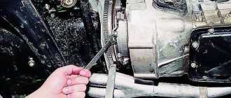
Replacing steering bearings on a vehicle such as a VAZ-2110 consists of a number of stages that must be carried out in the order in which they are listed below.
The whole process can be seen in the video:
First, you need to disconnect the battery on the car to prevent an electrical short circuit. It is enough just to remove one terminal where the “-” sign is indicated.
Then you need to remove the steering wheel. To do this, you will need to turn the car's ignition key, and also turn the steering wheel 90° in either direction. You will see a whole row of nuts, thanks to which the steering wheel is attached to the shaft
Using a special wrench, unscrew the nuts, and then carefully proceed to the recess to remove the steering wheel. This is done due to the fact that in some cars there is a system in the steering wheel that allows the steering wheel to be spring-loaded
If you do not take this into account, you may even get injured.
Using a special wrench, you need to unscrew the nuts where the steering column switch mechanisms are secured. Next, their bases must be moved towards the driver’s seat.
Having found the wire connected to the oil pressure sensor, you need to remove it.
When should you change your steering rack?
When the play at the steering wheel has increased and when the rack starts to knock, only in this case should you change it, but how can you check all this, you ask? Let's explain! It is best to check the knock on the rack not while the car is stationary, but when driving at speed because it will be more clearly audible, to do this, just find any sharp turn and calmly go through it, if you hear any extraneous sound (Knock), then stop, open the hood of the car and try to turn the steering wheel sharply, you will immediately understand if the rack is knocking, but if you want to clearly see how it can be checked, then in this case, watch the video just below in which everything is clearly shown. (In the video, the Lada Kalina car is taken as an example, but don’t pay much attention to this, and by the way, the rack on this car has already gone through quite a lot of mileage, so it’s already shaking even from the force of your hand)
Note! To preserve the life of the steering rack, try not to drive at high speed on uneven roads and large obstacles (for example, curbs), try not to drive over them, in extreme cases, just do it carefully and the rack will last you a long life!
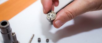
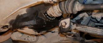
Steering ends: signs of malfunction
Steering ends are replaced when the following symptoms are observed: when driving over uneven surfaces, when accelerating or braking, a knock is felt, the steering wheel begins to vibrate and shake, play is noticed in the steering rod, and kickback is observed in the gas pedal. You can fully check the serviceability of the tips by checking the integrity of the anthers, etc.
Since these parts affect wheel alignment, they must be replaced on time so that the rubber does not start to wear unevenly.
The steering tips are changed on both sides at once (if one breaks, then after a while the other will break too).
When performing repair work to replace VAZ 2114 tips, the following tools are used:
- The key is “19”, the key is “24”, the key is “27”.
- Calipers.
- Press-out puller or mounting tool.
- Hammer.
- Brake fluid or chemical WD-40.
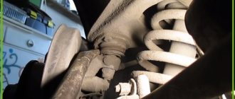
All work related to replacing tips on a VAZ 2114 can be performed either on a lift, or, as in this case, using a jack.
Replacement
Replacing tie rod ends involves performing the following actions:
- The machine is fixed in a stationary state (using wheel chocks and a hand brake);
- The car is raised to a height, the wheel is removed from the side where the replacement will be made;
- The steering wheel is turned as far as possible in the opposite direction to the wheel (left or right, depending on where the repair is being made);
- Next you need to remove the cotter pin, using a key set to “19”, unscrew the nut securing the tip;
- Using a special tool, you should press the finger out of the lever. If you don’t have a tool, you can use a hammer or a pry bar;
- Angles are also measured using a caliper to speed up the installation of wheels;
- Fixing the position of the coupling with a key set to “24”, you need to unscrew the lock nut with a key set at 27 (clockwise rotation). It is often twisted tightly (perhaps rusted or stuck). To make the nut start to unscrew, you should spray brake fluid or WD-40 on it. You can also use a hammer - gently tap it on the nut;
- The steering tip must be unscrewed with a universal key, moving counterclockwise;