Description of design
The service brake system is hydraulic, dual-circuit, with diagonally separated circuits. In normal mode, when the system is working properly, both circuits operate. If one of the circuits fails (depressurizes), the other circuit provides braking to the vehicle, although with less efficiency.
Elements of the brake system : 1 — front wheel brake disc; 2 — front wheel brake tube; 3 — front wheel brake hose; 4 — hydraulic drive reservoir; 5 — main brake cylinder; 6 — vacuum booster; 7 — brake pedal; 8 — rear wheel brake tube; 9 — pressure regulator; 10 — rear wheel brake mechanism; 11 — rear wheel brake hose; 12 - floating bracket
The service brake system includes wheel brakes, a pedal assembly, a vacuum booster, a master cylinder, a hydraulic reservoir, a pressure regulator in the rear wheel brakes, as well as connecting tubes and hoses. The brake pedal is a suspended type. A brake signal switch is installed in the pedal bracket - its contacts close when the brake pedal is pressed.
Pedal assembly with vacuum booster and main brake cylinder : 1 - brake pedal;
2 — brake pedal bracket; 3 - vacuum booster; 4 — hydraulic drive reservoir; 5 - main brake cylinder The vacuum brake booster is located between the brake pedal and the main brake cylinder and is attached with two nuts to the brake pedal bracket, which, in turn, is attached to the body. The vacuum amplifier is non-separable; if it fails, it is replaced with a new one. The brake master cylinder is attached to the vacuum booster housing with two studs. On top of the cylinder there is a reservoir for the hydraulic drive of the brake system, which contains a supply of fluid. There are markings for the maximum and minimum liquid levels on the tank body, and a liquid level sensor is installed in the tank lid, which, when the liquid level drops below o, turns on the alarm in the instrument cluster. When you press the brake pedal, the pistons of the master cylinder move, creating pressure in the hydraulic drive, which is supplied through tubes and hoses to the working cylinders of the wheel brake mechanisms.
Front wheel brake mechanism : 1 - shoe guide;
2 — caliper; 3 — brake pads; 4 — brake disc; 5 — brake shield; 6 — locking plate; 7 — screw securing the cylinder body to the caliper; 8 — hydraulic brake bleeder fitting; 9 — wheel cylinder; 10 — bolt securing the cylinder to the guide pin; 11 — guide pin; 12 — guide pin cover The front wheel brake mechanism is a disk one, with a floating caliper, which includes a caliper and a single-piston wheel cylinder, tightened together with two screws. The brake shoe guide is attached to the steering knuckle, and the bracket is attached with two bolts to the guide pins installed in the shoe guide holes. Protective rubber covers are installed on the fingers. Grease is placed in the holes for the pins of the pad guide. The brake pads are pressed against the guide grooves by springs. When braking, the fluid pressure in the hydraulic brake mechanism increases, and the piston, moving out of the wheel cylinder, presses the inner brake pad against the disc. Then the bracket (by moving the guide pins in the holes of the pad guide) moves relative to the disc, pressing the outer brake pad against it. In the cylinder body, attached to the caliper, there is a piston with a rubber sealing ring of rectangular cross-section. Due to the elasticity of this ring, a constant optimal gap is maintained between the disc and the brake pads.
Elements of the front wheel brake mechanism : 1 - bolt securing the cylinder to the guide pin with a locking plate; 2 — screw securing the cylinder to the caliper; 3 - cylinder; 4 - block; 5 — caliper; 6 - guide pin; 7 — guide pin cover; 8 — pad guide
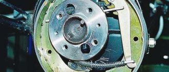
Rear wheel brake mechanism : 1 - lower tension spring;
2 — front block; 3 - pressure spring; 4 — spacer bar; 5 - working cylinder; 6 — upper tension spring; 7 — parking brake drive lever; 8 — rear block; 9 — tip of the parking brake cable. The rear wheel brake mechanism is drum-type, with a two-piston wheel cylinder, two brake pads and a device for automatically adjusting the gap between the pads and the drum. The automatic clearance adjustment device is located in the wheel cylinder. The main element of the device is a steel split thrust ring mounted on the piston with an axial clearance of 1.25–1.65 mm. The thrust rings (two per cylinder) are inserted into the cylinder with tension, providing a shear force along the cylinder surface of at least 350 N, which exceeds the force of the brake shoe tension springs. When the brake linings wear, the thrust rings shift under the action of the pistons by the amount of wear.
Elements of the rear wheel brake mechanism : 1 - front block;
2 - pressure spring; 3 - spacer bar; 4 - upper tension spring; 5 - finger; 6 — washer; 7 - cotter pin; 8 — rear block; 9 — parking brake drive lever; 10 - lower tension spring If the cylinder mirror is damaged due to mechanical impurities in the brake fluid, or due to corrosion (presence of water in the brake fluid), the rings may “sour” in the cylinder and one or even both pistons will lose mobility. In this case, the cylinders must be replaced.
Pressure regulator in the hydraulic drive of the brake mechanisms of the rear wheels : 1 - earring; 2 - bracket; 3 - elastic lever; 4 — bracket; 5 - drive; 6 - pressure regulator
Test results
The optimal adjustment of the “sorcerer” corresponds to the average factory settings, and a few percent can be gained only with individual correction for specific brake pads, tires, vehicle loading and road conditions. But it’s unlikely that anyone will start every trip with a test run.
It would seem that it is possible to reduce the braking distance by increasing the pressure in the rear brakes, but this threatens a loss of stability due to early blocking of the rear wheels. And today only ABS can provide maximum braking efficiency.
On a fully loaded car, depending on the position of the regulator, the spread of the braking distance is 8.3 m. The best results, as on the Niva, are with increasing pressure in the rear brakes. However, on a slippery road, even in smooth turns, early locking of the rear wheels is possible, leading to a skid. And at partial load, with the regulator position different from the base one, the braking distance only increases.
How to adjust the brake force regulator if you install so-called houses?
It is adjusted by moving the plate. There is no specific scheme to regulate it normally. By trial method, with an assistant. We set the regulator to a certain position. We slammed on the brakes, and people... looks when he takes the front and back. Ideally, the front should be taken first, the back later. Look here for the link text.
Or by placing washers, but again there is no system, accelerate the car and brake in the sand, rarely does anyone adjust it after installing the houses.
Subscribe
to our channel in
Index.Zen
Even more useful tips in a convenient format
Source
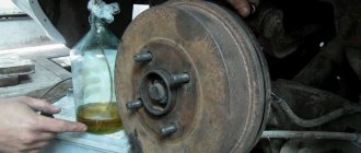
Bleeding the hydraulic brake system
We pump the brakes to remove air from the hydraulic drive after it has depressurized when replacing the master cylinder, wheel brake wheel cylinders, hoses, tubes, as well as in case of replacing the working fluid or when the brake pedal becomes “soft”. We remove air from the system when the engine is not running, first from one circuit and then from the other in the following sequence: – the brake mechanism of the right rear wheel; – brake mechanism of the left front wheel; – brake mechanism of the left rear wheel; – brake mechanism of the right front wheel. If air gets into one of the circuits, it is enough to bleed only this circuit, and not the entire hydraulic drive. Before pumping, check the level of working fluid in the brake system hydraulic reservoir and, if necessary, add fluid (see “Checking the fluid level in the brake hydraulic reservoir,” page 42). We bleed the brakes with an assistant. If the rear wheels are hanging...
...insert a screwdriver between the lever and the plate spring of the pressure regulator in the hydraulic drive of the brake mechanisms of the rear wheels, fixing the regulator piston in the recessed position. We clean the brake bleeder fitting of the right rear wheel from dirt...
...and remove the protective cap from it. Use a spanner wrench or an “8” socket to loosen the tightening of the bleeder fitting. We put a hose on the fitting, and immerse its free end in a container partially filled with working fluid. An assistant should vigorously press the brake pedal all the way 4-5 times and keep it pressed.
Using the “8” wrench, unscrew the bleeder fitting 1/2–3/4 turn. In this case, liquid with air bubbles will flow out of the hose, and the brake pedal should be pressed all the way. As soon as the liquid stops flowing out of the hose, tighten the fitting and only after that can the assistant release the pedal. We repeat pumping until air bubbles no longer appear in the liquid coming out of the hose. We remove the hose, wipe the bleeder fitting dry and put a protective cap on it. We pump as described above...
...brake mechanism of the left front wheel. Similarly, we bleed the brake mechanisms of the other circuit. When pumping, you need to monitor the fluid level in the brake hydraulic reservoir and add fluid if necessary. If, when you press the brake pedal, you feel its “softness” and increased travel, it means there is air left in the system. In this case, we repeat pumping until the pedal becomes “hard”, i.e., when pressed, go no more than half the distance to the floor. If air cannot be removed, check the tightness of connections, pipelines, hoses, master and working cylinders. We tighten leaking connections, replace faulty main and working cylinders (see “Brake system”).
practical guide
Rear brake mechanism
To replace the rear brake hose, you will need a special 10 mm wrench for the brake pipe fittings, an inspection ditch or an overpass.
Removal
1. We prepare the car for work and install it on an inspection ditch or overpass.
2. We clean the connections of the brake hose ends and pipes from dirt and corrosion. We treat the tube fittings with penetrating lubricant.
When performing the following operation, make sure that when unscrewing the fitting, the tube does not rotate with it. If the tube is “sour” in the fitting, replace it.
3. While holding the upper end of the hose from turning with a 15 mm open-end wrench, use a special 10 mm wrench to loosen the tube fitting.
4. Finally unscrew the fitting using a 10 mm open-end wrench.
5. To prevent brake fluid leakage, place a protective cap on the end of the brake pipe for the working cylinder bleeder fitting.
6. Remove the upper end of the brake hose from the hole in the body bracket.
7. In the same way, unscrew the tube from the lower tip of the brake hose and release it, leading it out of the hole in the bracket installed on the rear axle beam.
8. Remove the hose from the car.
Installation
1. Install the hose in reverse order.
2. We remove air from the hydraulic brake drive and check the connections of the brake hose and pipes for leaks.
Removal
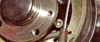
1. Remove the brake pads and brake cylinder from the shield.
2. Using an 8 mm hex wrench, through the hole in the hub flange, remove the four bolts securing the hub axle.
3. Passing the parking brake cable through the hole in the support shield, remove the axle assembly with the hub and shield.
4. We fix the shield in a vice with soft pads on the jaws. Using a large Phillips head screwdriver, remove the two screws securing the shield.
5. Remove the shield from the hub axle.
Installation
1. Install the shield in reverse order.
2. Remove air from the hydraulic drive system.
3. Adjust the parking brake system.
We replace the cylinder when brake fluid leaks and when the piston (pistons) in the cylinder “sour,” as a result of which one or both pistons stop moving in the cylinder.
To perform the work, you will need a special 10 mm wrench for the bleeder fittings of the working cylinders and the brake pipe fittings.
1. We prepare the car for work.
2. Remove the brake drum.
3. Raise the parking brake lever all the way.
4. Treat the brake pipe fitting with penetrating lubricant.
5. Remove the protective rubber cap from the bleeder fitting of the working brake cylinder and use a special or 8 mm spanner to unscrew the fitting.
When performing the following operation, make sure that when unscrewing the fitting, the tube does not rotate with it. If the tube is “sour” in the fitting, replace it.
6. Use a special 10 mm wrench to loosen the brake pipe fitting.
7. Finally unscrew the fitting with a 10 mm open-end wrench.
8. Using a 10 mm wrench, remove the two bolts securing the working cylinder.
9. To prevent brake fluid from leaking out of the tube, we put a rubber cap on the bleeder fitting.
10. Remove the cylinder from the shield.
1. We clean the parts of the brake mechanism from dirt and rust, degrease the working surface of the drum, remove minor oiling of the brake pads using sandpaper.
2. Install the new cylinder in the reverse order.
3. Install the brake drum.
4. Bleed the brake system and make sure that the connection between the brake pipe and the working cylinder is tight.
Rear brake pads must be replaced if the thickness of the lining of any of the pads is less than 1.5 mm, as well as if the lining is detached from the base of the pad.
The brake pads of the rear brake mechanisms can only be replaced as a set, that is, on both wheels.
To do the job you will need pliers with thin curved jaws.
Removing rear brake pads:
1. We prepare the car for work.
Design features of Lada Priora car brakes
The car is equipped with two braking systems - working and parking.
The service braking system is designed to reduce the speed of the vehicle, until it comes to a complete stop and briefly holds the vehicle stationary.
The service brake system is dual-circuit, diagonal, hydraulically driven, and consists of a master cylinder with a vacuum booster, four wheel brakes and a fluid pressure regulator in the rear brakes.
The front wheel brakes are ventilated discs, the rear wheels are drum brakes.
Each of the car’s circuits includes brake mechanisms for two wheels: one front and one rear, located diagonally on the car.
One circuit includes the brake mechanisms of the front right and rear left tracks, and the second circuit includes the brake mechanisms of the front left and rear right tracks.
If one circuit fails, the second circuit, albeit with less efficiency, will ensure the vehicle stops.
"Wizard" OR ABS?
And yet, such a regulator on a modern car is a legend of deep antiquity. It cannot compete with ABS, especially if the driver is an average driver who does not know extreme driving techniques. The curb weights of Kalina and Priora are almost the same - the difference is less than a percent. Using the same tires that were on the Kalina, the Priora with ABS showed the best results under any load. Moreover, no dosing of force on the brake pedal was required, you just press with all your heart, and the electronics do the rest.
Test results:
Brake system of the Lada Priora car
Working brake system of a Lada Priora with ABS:
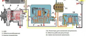
1 — brake mechanism of the front left wheel; 2, 5, 13, 18 — brake hoses; 3, 8, 12, 19 — brake pipes; 4 — main brake cylinder; 6 — brake mechanism of the front right wheel; 7 — front right wheel speed sensor; 9 — reservoir of the main brake cylinder; 10 - vacuum booster; 11 — brake pedal; 14 — rear right wheel rotation sensor; 15 — brake mechanism of the rear right wheel; 16 — master disk of the rear left wheel speed sensor; 17 — brake mechanism of the rear left wheel; 20 - ABS hydraulic modulator
Note: The left brake mechanisms are also equipped with wheel speed sensors, which are not visible in the figure. On a vehicle not equipped with an anti-lock braking system, a fluid pressure regulator is built into the hydraulic rear brake actuator.
The car is equipped with two braking systems - working and parking.
The service braking system is designed to reduce the speed of the vehicle until it comes to a complete stop and briefly hold the vehicle stationary.
The service brake system is dual-circuit, diagonal, hydraulically driven, and consists of a master cylinder with a vacuum booster, four wheel brakes and a fluid pressure regulator in the rear brakes. The front wheel brakes are disc, non-ventilated, the rear wheels are drum.
Each of the car’s circuits includes brake mechanisms of two wheels (one front and one rear), located diagonally on the car. One circuit includes the brake mechanisms of the front right and rear left wheels, and the second circuit includes the brake mechanisms of the front left and rear right wheels. If one of the circuits fails, the second circuit, although with less efficiency, will ensure that the car stops.
The fluid pressure regulator limits the flow of fluid to the rear brake mechanisms when there is insufficient load on the rear axle, thereby preventing the rear wheels from locking and the rear axle of the vehicle from skidding during sudden braking. The regulator body has a control hole closed with a plastic plug. Liquid leakage from this hole indicates leakage of the regulator rings.
To reduce the force applied by the driver to the brake pedal, a vacuum booster is installed in the brake system drive, which operates due to the vacuum generated in the intake manifold of a running engine.
Do not turn off the engine until the vehicle is completely stopped.
A brake fluid reservoir is installed on the brake master cylinder body. A sensor for insufficient brake fluid level is built into the reservoir cap. If the liquid level in the tank drops dangerously, the sensor turns on the warning lamp on the instrument panel.
Some cars are equipped with a braking system with ABS (anti-lock braking system). A four-channel system from Bosch is used. The channels are connected according to a diagonal pattern. The executive element of the anti-lock braking system is a hydraulic modulator. This is a complex assembly in which a hydraulic pump and solenoid valves are built in. It is installed in the engine compartment on the left side. The operation of the hydraulic modulator is controlled by an electronic unit installed on the hydraulic modulator. The control unit also monitors the serviceability of all elements of the ABS system.
The front and rear brake mechanisms are equipped with front wheel speed sensors. Inductive type sensors. To operate the sensors installed in the front brake mechanisms, gears are made on the housings of the external hinges of the front wheel drives. To operate the sensors installed in the rear mechanisms, master discs are installed under the brake drums. Pulse signals from the sensors enter the control unit. When one of the wheels is blocked, the hydraulic modulator, at the command of the control unit, limits the pressure in the corresponding channel. If a malfunction is detected, the control unit informs the driver using a warning lamp on the instrument panel. The problem can be determined by fault codes at a specialized service station that has diagnostic equipment. On a vehicle with ABS, a second additional relay fuse box is installed in the engine compartment. The block contains all the fuses and relays of the ABS system.