Mechanical fuel pump design
A mechanical fuel pump, used in engines with a carburetor injection system, is attached to the cylinder block or cylinder head with screws. In most cases, a diaphragm pump is used to supply fuel. The pump attached to the block is driven by a crankshaft on which a special eccentric cam is provided. This cam presses on the rod, which compresses the membrane located inside the housing.
Mechanical fuel pumps had a manual fuel pumping system in case the system “dryed out” after a long stay.
When the cam is pressed, the volume of the pump's internal chamber decreases, and when it increases again, gasoline is sucked into the chamber. To prevent fuel from flowing back into the pipeline, the supply pipe is equipped with a check valve. When the next press occurs, fuel exits through the discharge pipe and is supplied to the carburetor, and a new portion from the pipeline enters the chamber. The pressure in the supply line can be regulated by installing a more or less stiff spring, but for design reasons it cannot be high (this is due to the fact that the stiffness limits of the spring are limited by the elasticity of the metal from which it is made).
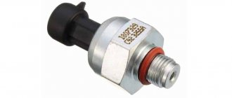
Diesel engine booster pump for fuel injection pump
So, a low pressure fuel pump (LPFP) is needed to pass diesel fuel through the filters under low pressure and then supply fuel to the fuel injection pump. In this case, there are two operating modes of the device. The first mode is the so-called preparatory mode, while the second mode is working.
As for the preparatory mode, at this moment the piston in the pump moves upward, and in parallel, the effect of the eccentric is noted, which compresses the spring. As a result, fuel begins to move in the chambers and also passes between the filters. The operating mode of the low-pressure pump is the reverse movement of the piston (the piston moves viz).
It is worth noting that the low pressure pump pumps slightly more fuel than the engine needs for smooth operation. Such pumping “with a reserve” allows you to maintain optimal pressure in the power system, avoiding increased loads.
Why did you need to switch to electric pumps?
With the advent and proliferation of electronically controlled injection systems, the use of mechanical pumps has become impractical. The fact is that it is necessary to maintain a higher pressure in the fuel line of injection systems, and it is impossible to achieve it using a mechanical diaphragm pump. In the injection system line, it is necessary to maintain a constant fuel pressure of 1 to 5 bar for uninterrupted operation of the injectors. In addition, the fuel flow supplied by the mechanical pump due to cyclic operation had significant pulsation. If fuel was supplied to the injector in this mode, the injectors would experience periodic fuel starvation, which would lead to engine malfunctions.
Application
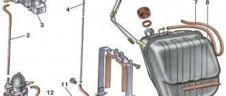
The fuel priming pump is used in most cases when there is a significant distance between the fuel tank and the injection pump. Most often, the pump is attached to the injection pump housing. Depending on the layout of the engine in the engine compartment and the specific operating conditions, different layouts of fuel lines are required, especially to ensure fuel return. In Fig. 1 and 2 show two possible types of such schemes. If a fine fuel filter is located near the engine, the heat generated by the latter can lead to the formation of vapor locks inside the fuel line system. To prevent this, an excess amount of fuel is pumped through the intake cavity, thereby cooling the injection pump. With this connection scheme (Fig. 1), excess fuel enters the return line through bypass valve 6 and returns to tank 1.
Rice. 1 and 2 1. Fuel tank 2. Fuel priming pump 3. Two-stage fuel filter 4. In-line injection pump 5. Injector assembly 6. Bypass valve 7. Bypass throttle
Electric fuel pump design
A modern electric fuel pump consists of two parts - a drive and a pump part. In the vast majority of cases, the role of the drive is performed by an electric motor.
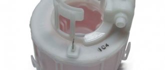
In the fuel systems of many modern cars, for example, a number of Peugeot models, the fuel filter is integrated into the pump and changes along with it
Both parts are placed in a single metal case. The pump housing is usually combined into a single fuel module with a flow sensor, fuel filter and fuel intake. In most cases, modern cars use submersible pumps and the fuel module is built directly into the tank.
Most often, pumps of three main designs are used in the fuel supply system: roller, gear and centrifugal.
Principle of operation
- When the booster pump is not working, the inlet and discharge valves are closed, and the above- and under-piston space is filled with fuel.
- When the cam shaft of the fuel pump rotates, the pusher and piston, under the action of the shaft eccentric and springs, perform a reciprocating movement.
- When the cam lobe moves away from the pushrod, the piston and tappet move under the action of the springs towards the cam shaft. In this case, pressure is created in the sub-piston space, and a vacuum is created in the space above the piston. The discharge valve closes, and the intake valve opens, and fuel from the intake port A enters the above-piston space, and from the sub-piston port it is squeezed out through channel B into the fuel filter and then into the head of the fuel pump.
- When the eccentric protrusion runs into the pusher, the latter, with the help of a rod, moves the piston, compressing the spring. Pressure is created in the space above the piston, and vacuum is created in the space below the piston. The intake valve closes and the discharge valve opens, allowing fuel to flow from above the piston to below the piston. Thus, fuel is supplied to the fuel pump when the piston moves towards the eccentric under the action of a spring, and when the piston moves under the action of the eccentric, it flows from the space above the piston to the space below the piston. During subsequent strokes of the piston, the process is repeated in the same sequence.
- When the pressure in discharge channel B increases (for example, when fuel consumption by the fuel pump decreases or the fuel filter is clogged), the spring, moving the piston, cannot overcome the resistance of the fuel, and the piston stops.
- The position of the piston in this case depends on the fuel consumption. The lower the fuel consumption, the higher the pressure in the discharge channel, the earlier the piston stops and the shorter its working stroke.
- With a smaller piston stroke, less fuel is supplied to the discharge channel. Therefore, even with low fuel consumption, the pressure in the discharge channel does not rise above a certain level.
- This automatically limits the maximum fuel pressure supplied by the booster pump to the system. This should be taken into account during operation.
- If the fine fuel filter is not replaced in a timely manner, its supply to the system becomes insufficient and the diesel engine loses power.
If the filter element becomes so clogged that its hydraulic resistance becomes greater than the spring force, the fuel supply will stop completely and the diesel engine will stop.
a — injection of fuel into the system; b - fuel flow; c — cessation of fuel supply; 15 - eccentric.
TNND and safety
At first glance, the location of an electric fuel pump in a fuel tank filled with fuel seems strange, to say the least. However, this arrangement offers a number of significant advantages, including from the point of view of fire safety.
The main problem with fuel lines during the period when mechanical pumps became widespread was the boiling of fuel due to the heat generated by the engine. This problem has been solved in systems based on electric pumps. The boiling point of fuel under pressure increases, and in addition, a constant flow of gasoline moving along the highway does not heat up as much.
The fuel pump power supply circuit breaker is included in the standard set of anti-theft equipment
The pump located in the tank is located as far as possible from the engine and is cooled by the gasoline in which it is immersed.
All components of the pump, including the electrical wires that supply it, are in constant contact with the fuel. Gasoline has high electrical resistance, which prevents short circuits, so as long as there is always fuel in the tank, this installation is safe. If the pump is not completely immersed in gasoline, it may overheat and even ignite the vapors as a result of a short circuit. However, due to an effect called the flammability limit, the bulk of the fuel in this case cannot ignite.
Classification
The most commonly used classification of fuel pumps - by engine type - was given above. However, other signs are also used that make it possible to divide the mechanism under consideration into types. For example, based on their location in the car, a distinction is made between submersible pumps, which are installed directly in the fuel tank, and pumps, mounted directly to the engine power unit.
Based on the type of drive, fuel pumps are divided into mechanical and electric. The first type is used in carburetor engines and older models of diesel units. An alternative option is used much more often today and is installed both in injection gasoline engines and in modern diesel power plants.
Fuel pump control
The operation of the fuel pump begins when the relay is activated immediately after the ignition is turned on, even before the engine starts. This is necessary to create pressure in the line before starting. Modern engine control units have a function to turn off the relay even if the ignition is on and the engine is running. This can happen, for example, in the event of a collision. In the event of a car overturn, for example, the fuel pump is switched off immediately, based on a signal from a special valve that switches if the pump is in a different position relative to the ground, which prevents a fire.
Along with this function, the control unit program may include the ability to turn off the fuel pump in the event of a drop in oil pressure in the engine (which can lead to rapid overheating of the cylinder block and a fire).
Power system diagram
The diesel engine power system diagram includes the main components, which include:
- Fuel tank;
- Fuel filters (coarse and fine);
- Fuel pump, booster;
- High pressure fuel pump (HPF);
- Injectors;
- Pipeline for pumping fuel under low pressure;
- High pressure pipeline;
- Air filter
The fuel system circuit has auxiliary components, which include electric pumps, exhaust parts, soot filters, mufflers, etc. The general design of the power system involves dividing fuel equipment into two groups:
- Fuel supply equipment;
- Air supply equipment.
The fuel equipment of diesel engines can have a different design; a split type system is by far the most common. This system is characterized by the separation of the fuel injection pump and injectors into separately functioning devices.
The fuel travels through high and low pressure overpasses. Checking the fuel supply hoses is a prerequisite for operating the power plant.
Storage, filtration and supply to the injection pump occurs at low pressure. After which, the fuel pump raises the pressure in the system for proper dosing and supply of a portion of fuel into the combustion chamber at the right time.
The diesel engine power supply system is served by two pumps:
- High pressure pump;
- Pump, fuel pumping.
The fuel pump supplies diesel fuel from the tank to the coarse and fine filters and then to the pump that creates high pressure. The liquid travels this path with a relatively low pressure.
Passing the injection pump, the fuel pressure is pumped to a high level. The operating order of the cylinders determines the supply of the working mixture. The pump that creates high pressure has several sections, each of which is responsible for a specific engine cylinder.
The power supply system of a two-stroke diesel engine may be of an undivided type. For such systems, a special device, a pump-injector, is used. This is a kind of combination of a fuel pump that creates high pressure and injectors into one device.
The design principle of operation of the diesel engine power supply system, which is most widespread, involves the location of injectors in the cylinder head. The main task of this arrangement is precise atomization of fuel in the combustion chamber. A large volume of diesel fuel is supplied to the fuel injection pump; its excess is discharged back to the gas tank through drain pipes.
Nozzles can be of two types:
- Closed type;
- Open type.
Closed type nozzles are more widely used. These injectors have a special shut-off needle that closes the fuel supply hole. Therefore, the injector cavity is connected to the combustion chamber only when the hole is opened and liquid is injected.
Low pressure pump in the diesel fuel supply system
Electric pumps are also used in cars with diesel engines. In modern systems, they are called booster pumps and serve to supply fuel under relatively low (usually no higher than 5 bar) pressure to the inlet cavity of the injection pump.
Often the booster pump is integrated into the high pressure fuel pump housing. Injection pump, since the injection pump needs a constant flow of fuel in the suction part for uninterrupted stable operation in any mode.
Design features of rotary injection pumps
Rotary pump designs are widely used and may differ in design features. The main difference lies in the method of forming a closed chamber for the supplied fuel. Design Features:
- The basis of the design is the body, which is often made in a cylindrical shape. The body has slots of variable cross-section.
- The rotation is transmitted to a slotted rotor, into which rollers and flat blades are inserted.
- At the moment of rotation, the blades come into contact with the surface of the housing. This creates separate chambers that capture the fuel and discharge it through the outlets.
It is worth considering that this design has a fairly large number of disadvantages. The main one is the need to create a complex drive from a crankshaft or other drive. This point significantly increases the cost of the unit and reduces its reliability. To increase the reliability of the unit, an electric drive is installed, which ensures a reliable supply of fuel to the high-pressure pump.