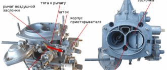
The K-151 carburetor is designed to equip ZMZ four-cylinder power units with a volume of 2.45 liters, which were once equipped with cars of the GAZ and UAZ families. The production of three modifications of the engine power supply device has been launched: K-151, K-151V and K-151N. The K-151N modification is more focused on UAZM engines.
Like all components and assemblies in the car system, the carburetor must be regularly maintained and repaired at the first symptoms of a malfunction. In this article we will look at the features of the design, adjustment, repair and connection of the K-151 carburetor.
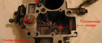
Secondary modification chamber
The secondary chamber in this modification includes a powerful pump and a set of discs.
The bypass valve in this case is located at the bottom of the chamber. It should also be noted that this model has a jet that interacts with the fuel system. If problems are detected, it is recommended to immediately check the functionality of the central fitting. If the needle does not move, it means the canal is clogged. The easiest way to clean the chamber is with a nozzle. Additionally, it is blown with a jet of air under pressure.
It is important not to damage the valve system. The idle speed of the K-151 carburetor is adjusted with a holder
Some people have problems with the regulator located in the camera. In this modification, it is connected to a roller.
To check the regulator, you need to remove the cover and disconnect the upper pump. Only after this does the stand itself come out. First of all, the roller is disconnected. After this, you need to inspect the base of the regulator. This carburetor has a small stand. If it is deformed, then the model will have to be completely replaced. Another problem may lie in a deviated septum. This happens due to overload of the valves. The partition can be changed separately. In this case, there is no need to completely remove the regulator.
Connecting hoses
The complex structure of the K-151 is also evident when it is connected to the engine. It provides for the use of a whole range of hoses, but only two different sizes are used, so it is quite possible to confuse them, and the motor will malfunction in certain modes. The order of connecting the hoses to the carburetor:
Fuel is supplied through the fuel pipe to a fitting located under the float chamber on the engine side; the return hose is put on the lower fitting - it looks in the direction opposite from the power unit and is located below the inlet; two small cross-section hoses are connected to the solenoid valve, the other end of one of them is connected to the economizer valve; the second end of the thin hose is put on the fitting located in the lower part of the K-151 on the back side of the DZ body (there are two of them standing next to each other, we use the lower one); onto the upper fitting of this pair we pull the hose that goes to the vacuum ignition advancer (it is located on the distributor); a large diameter fitting on the DZ housing is used to connect the forced crankcase ventilation pipe, a device usually located on the valve cover; a small diameter fitting located in the middle part of the K-151 is used to connect a thermal vacuum switch, however, this pipe is used only if the engine has an exhaust gas recirculation system. If such a system is not provided for a specific modification of the motor, simply install a plug on this fitting
True, such a precaution is unnecessary - there is no air leak through this fitting.
If you lack experience, these connections should be made by consulting the instructions for the device.
Connecting carburetor hoses K-151D
Main malfunctions of the K151 carburetor
Carburetor for Moskvich-412: description, adjustment and photo
During the operation of these dosing devices, malfunctions are possible, which are detected by signs of engine malfunction.
Doesn't hold idle
This malfunction often occurs due to a lean fuel mixture. The reason for this is a failure in the neutral settings of the carburetor or simple clogging of the channels. Another possibility is that the float in the chamber is installed crookedly.
Carburetors equipped with an electric valve are regulated as follows:
- loosen the XX adjustment screw slightly;
- check the speed;
- if they have changed, tighten the screw until the speed returns to normal.
Fills (overflows)
Overfilling, which occurs due to over-enrichment of the gasoline mixture, is also not uncommon.
It is easy to determine this malfunction; just pay attention to the strong smell of fuel and fuel leaks from the nozzles. Black smoke may also come out of the exhaust pipe.
As a rule, overflow prevents the engine from starting normally. This is especially true on warmed-up engines, which even after a successful restart attempt are unstable. When the accelerator is activated, dips and jerks begin.
To correct the situation, just adjust the float chamber. There are several options on how to proceed:
- Damage to the needle valve. It is necessary to check the functionality of the needle - a vacuum is applied to it and the opening/locking is tested. Read more about valve repair below;
- Valve stuck. In this case, you need to tap the carburetor cover lightly with a hammer. This will affect the valve. It is possible that the seal has dried out or the element is not wrapped tightly enough;
- Valve sticking. This happens due to oil getting into the fuel. Impurities can settle in the fuel tank and from there penetrate into the metering device in the form of a sticky solution. The problem can be solved by replacing the entire repair kit, possibly together with the jets. A less expensive option is to treat the needle with a special paste;
- Float destruction. The damaged element will simply begin to sink in gasoline, dragging the valve with it. For this reason, liquid will be constantly pumped into the chamber, which will cause overflow. A leaky float can be identified by the sound of the liquid in it - just remove it and shake it over your ear. As a last resort, the part is allowed to be soldered;
- The float is stuck, touching the walls of the housing. This already indicates an incorrect position setting. It is also recommended to check the float stroke with the top of the carburetor placed vertically - naturally, the top must be removed before the test.
System freezing
In autumn, and especially in winter, K-151 can freeze. This happens when driving on roads at high speed. The reason is that the air damper remains constantly open. This situation poses a big problem. The ice will close the air holes in the dispenser. The mixture will begin to become over-rich, and the spark plugs will become overgrown with soot.
What to do? While driving on the highway, determine by ear that the nature of the internal combustion engine has changed, and stop. Remove the top of the air filter and carefully inspect the diffusers. If there are solid drops in this place, wait a little - the ice will melt and you can continue on your way.
Other causes of carburetor freezing:
- solenoid valve XX is damaged;
- the filter mesh is clogged or damaged;
- the air damper does not close completely;
- sucks air through the device connections.
Repair of carburetor K-151 of GAZ-3110 car
Solex carburetor: setting, adjustment, removal
The carburetor should be removed from the engine mainly to flush it from dirt and resins, since repairs and adjustments of most of its systems and elements can be carried out without dismantling.
Removal
1. Remove the air filter.
2. Unscrew screw 6 securing rod 2 to the choke drive lever, unscrew screw 1 securing rod to the bracket and disconnect the rod from the carburetor. Unscrew the nut 7 securing the accelerator cable to the throttle valve drive sector, move the oil seal 5, unscrew the nut 4 and remove the rod 3 from the bracket and the throttle valve drive sector.
3. Having loosened the clamp clamps, remove the fuel supply hoses 2 and drain 3 from the carburetor fittings, hose 1 of the crankcase ventilation system, the vacuum hose for controlling the forced idle economizer (EPHH) on the back side of the carburetor and hose 5 to the electromagnetic valve of the EPHH system, to the vacuum to the ignition distributor corrector 7 and to the exhaust gas recirculation thermal switch4. Disconnect wires 6 from the microswitch of the EPHH system.
4. Unscrew the four nuts 1 securing the carburetor to the intake pipe, remove the cable holder 2 and dismantle the carburetor.
Disassembly
It is not recommended to unscrew the screws securing the throttle valves on the axles and remove the valves unless absolutely necessary, since their displacement can lead to jamming of the valves in the channels. The brass connecting tubes of the channels pressed into the body should not be removed in order to avoid disturbing the tightness of their fit.
The carburetor should be disassembled only as a last resort if washing and blowing with compressed air without disassembly does not eliminate sticking of the throttle and air valves and does not lead to complete cleaning of the jets and channels from deposits.
1. Disconnect rod 1 of the air damper drive from the profile lever by removing cotter pin 2 from the hole at its curved end.
2. . Remove the seven screws securing the cover to the body and remove the carburetor cover
3. Unscrew the two screws securing the throttle body and, disengaging the connecting link, remove the body
4. Unscrew the three fastening screws 1 and remove the cover 2 of the vacuum diaphragm of the carburetor starting device.
5. On the back side of the carburetor cover, remove the bent end of the carburetor trigger diaphragm rod from engagement with the trigger lever. Remove diaphragm 1 from the carburetor cover.
6. Disconnect tension spring 1 of the air damper from the cover pin. Unscrew two screws 2 and remove cover 3 of the float chamber ventilation channel. Unscrew the fastening screw 4 and remove the econostat sprayer 5.
7. Unscrew the mounting screws and remove the starter drive levers.
Rice. 7
8. Carefully remove the heat-insulating gasket from the lower flange of the mounting housing.
How to set it up yourself?
To adjust the K-151 carburetor you will need the following minimum set of tools:
- flat and Phillips screwdrivers;
- ruler;
- calipers;
- adjusting probes and drill (d= 6 mm);
- tire pump.
To dismantle the carburetor you will need open-end or ring wrenches for 7,8,10 and 13.
Before tuning, remove the top part of the carburetor and clean it of dirt and carbon deposits. At this stage, you can check the fuel level in the float chamber. This will be discussed in detail below.
The carburetor should only be removed if absolutely necessary! When blowing with compressed air and washing do not eliminate the consequences of jamming of dampers and contamination of jets (channels).
It is important to understand that a carburetor that is not too dirty works the same as a perfectly clean one. The moving parts in it clean themselves, and it is not easy for dirt to get inside. Therefore, it is often necessary to clean the carburetor from the outside, in places where large pieces of dirt stick to mutually moving parts (on the lever mechanism and in the starting system).
We will consider partial disassembly of the device with all adjustments and subsequent assembly.
Removal and disassembly algorithm
Step-by-step algorithm for removing and disassembling the K-151 carburetor:
- open the hood of the car and remove the air filter housing. To do this, unscrew and remove the top fastening, and then the filter element itself. Unscrew the 3 nuts securing the filter housing with a 10mm wrench and remove it;
- remove the plug of the EPHH microswitch;
- Having disconnected all the hoses and rods, use a 13mm wrench to unscrew the 4 nuts holding the carburetor to the manifold. Now we remove the carburetor itself. Important! It is better to mark the hoses and connection points before removal, so as not to confuse anything during assembly in the future;
- disassemble the carburetor. Unscrew the 7 fastening screws with a screwdriver and remove the top cover, not forgetting to disconnect the air damper drive rod from the lever;
- We wash the carburetor using a special cleaning agent. Gasoline or kerosene is also suitable for these purposes. The jets are purged with compressed air. We check the gaskets for integrity and, if necessary, replace them with new ones from the repair kit. Attention! Do not wash the carburetor with strong solvents, as this can damage the diaphragm and rubber gaskets;
- While the carburetor is removed, the starting device can be adjusted. If it is not working properly, starting the engine in cold weather will be difficult. We'll talk about this setting later;
- screw the carburetor into place along with the top cover. We connect the microswitch block and all the necessary cables.
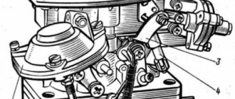
If you suddenly forget which hose to plug into where, we suggest using the following diagram (for the ZMZ-402 engine):
Connection diagram for carburetor hoses for ZMZ 402 engine
4- fitting for vacuum selection into the vacuum ignition timing regulator (VROZ); 5-vacuum sampling fitting to the EPHH valve; 6 – crankcase gas intake fitting; 9-vacuum sampling fitting to the exhaust gas recirculation valve; 13- fitting for supplying vacuum to the EPH system; 30- channel for fuel removal; 32 - fuel supply channel.
For the ZMZ 406 engine, a special K-151D carburetor is provided, in which there is no fitting number 4. The distributor function in it is performed by an electronic automatic pressure sensor (APS), which is connected by a hose to the intake manifold pipe, where it reads the vacuum parameters coming from the carburetor. Otherwise, connecting the hoses on the 406 engine is no different from the diagram presented above.
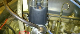
How to adjust the fuel level of the float chamber?
The normal fuel level for K-151 carburetors should be 215 mm. Before measuring, pump the required amount of gasoline into the chamber using the hand pump lever.
Fuel level control using the communicating vessel method
The level can be checked without disassembling the top of the carburetor (see figure above). A fitting with an M10×1 thread is screwed into place in place of the drain plug of the float chamber. A transparent hose with a diameter of at least 9 mm is put on it.
If the level is not correct, then unscrew the carburetor cap to access the float chamber. As soon as you remove the top, immediately measure the level using a caliper depth gauge (from the top of the carburetor to the fuel line). The fact is that gasoline quickly evaporates when exposed to the atmosphere, especially in hot weather.
An alternative option for level control is to measure the distance from the top plane of the chamber connector to the float itself. It should be within 10.75-11.25 mm. In cases where this parameter deviates, you need to carefully bend the tongue (4) in one direction or another. After each bending of the tongue, gasoline should be drained from the chamber and then refilled. In this way, fuel level measurements will be the most accurate.
An important condition for a working fuel level control system is the integrity of the rubber sealing ring (6) on the shut-off needle , as well as the sealed float.
Adjusting the starter
Before you start adjusting the starting device, you need to carefully familiarize yourself with its structure and circuit.
Starter circuit
Adjustment algorithm:
- Having turned the throttle lever, at the same time we move the air damper lever (13) all the way to the extreme left position. We fix it with rope or wire. Using adjusting feeler gauges, measure the gap between the throttle and the chamber wall (A). It should be within 1.5-1.8 mm. If the gap does not correspond to the standard, loosen the lock nut with a key “8” and use a screwdriver to rotate the screw to set the required gap.
- Let's start adjusting the rod length (8). It links the trigger control cam and the choke control lever. By unscrewing the threaded head 11 (on early versions of the carburetor), we set the gap (B) between levers 9 and 6 equal to 0.2-0.8 mm.
- In this case, lever 6 should touch the antenna 5. If this is not the case, then unscrew the screw and turn lever 6 to the left until it stops with the antenna of the two-arm lever (5). On late model carburetors, the gap (B) is set by unscrewing the screw securing the lining to cam 13 and moving it up along with the rod and then tightening the screw.
- Finally, check the gap (B). Having sunk rod 1, insert a 6 mm drill into the resulting gap (B) (deviations of ±1 mm are allowed). If it does not fit into the hole or is too small for it, then by unscrewing screw 4 and moving the double-armed lever, we achieve the required clearance.
Useful video
A visual video about setting up the starting device of the new K-151 carburetor model:
Setting up the idle system
Idle speed adjustment is carried out in order to ensure stable engine operation with a minimum content of harmful carbon monoxide (CO) in the exhaust gases. But since not everyone has a gas analyzer, you can make adjustments using a tachometer, relying on your own sensations from the engine.
First, start the engine and warm it up (quantity screw 1 is screwed in in an arbitrary position). Remove the shank stop on the quality 2 screw, if there is one.
Important! The air damper must be open when adjusting the idle speed.
After warming up with the quality screw, we find a position at which the engine speed will be maximum (a little more and the engine will stall).
Next, use the quantity screw to increase the speed by about 100-120 rpm above those that correspond to idle in the factory instructions.
After this, the quality screw is tightened until the speed drops by 100-120 rpm, i.e. to the specified factory standard. At this point, the idle speed adjustment is complete. It is convenient to control measurements using a remote electronic tachometer.
Screws for quantity (1) and quality (2) on the K-151 carburetor
With the use of a gas analyzer, the control (CO) in the exhaust gases should not exceed 1.5%.
Interesting video
We present to your attention an interesting and, most importantly, useful video with which you can easily adjust the idle speed on a carburetor of any modification of the K-151:
Scheme for reducing consumption on the K-151 carburetor
Adjusting the gas-53 carburetor with your own hands: and the device
Location and designation of carburetor jets K-151
First of all, you need to clog the hose that comes from the valve cover at the bottom of the carburetor; after these steps, the idle speed will become stable.
The procedure for reducing fuel consumption on the carburetor to 151:
- It is necessary to adjust the air and fuel jets.
- Adjust the ignition to the point of detonation.
- Correctly adjust idle speed.
| Turn the large screw approximately the required number of revolutions. | Small screw - turn in both directions until maximum speed is reached. |
| Large - quantity | Small – quality |
| Then use the large screw to lower the speed - not much more than the prescribed ± 100. And level it to the required amount with the small screw. |
This is how to remove, install and configure the K 151 carburetor on a UAZ. As you can see, there is nothing complicated in this procedure and any novice driver can cope with it. We wish you good luck on the roads!
Adjustment
If without experience it is quite difficult for car owners to repair the K-151 unit with their own hands, then it is easier to master the adjustment, the main thing is to understand the principle of operation of the device and act according to the instructions. There are several types of “one hundred and fifty-first” adjustments:
- idle move;
- air damper position;
- gasoline level in the float chamber;
- throttle position.
Changing the fuel level in the float chamber should be trusted to experienced carburetor specialists, but any driver can adjust the idle speed independently. We carry out the procedure as follows:
Float chamber
The advantage of the K-151 is the location of the shut-off needle in the carburetor body. This makes it easier to adjust the fuel level and check the needle for tightness. It is enough to remove the carburetor cover, pump up fuel using a manual pump and, bending the upper float tendril, set the specified level.
The position of the fuel level determines the amount of fuel supplied and, as a result, the basic performance of the vehicle. Its recommended value is given in the carburetor maintenance instructions. When the fuel level is low, the mixture becomes leaner, causing jerks and “dips”, which usually appear during acceleration and driving at high speeds. For K-151, this can happen at the recommended fuel level (distance to the connector plane is 21–23 mm). In this case, you should increase the level by reducing this distance to 19 mm by bending the float tongue down. After adjustment, you should make sure that the plane of the tongue at the point of contact of the needle is approximately perpendicular to the axis of the needle, otherwise it may jam due to misalignment.
An excessive increase in the fuel level leads to over-enrichment of the working mixture, causing deterioration in starting performance, spark plugs, smoke, and increased fuel consumption. Fuel overflow may occur due to a leak in the locking mechanism. To check it, you can remove the filter cover or adapter and, using the lever of the fuel pump, see if there is a fuel leak (with the engine idling, you can make sure that there is no drip in the second chamber of the carburetor from the GDS nozzle - Ed.).
K-151 carburetors use locking needles with sealing washers, which reduces the requirements for the precision of manufacturing the needle itself and its body (and also makes it possible to do without a special damping device in the valve - Ed.). But due to possible deformation of the sealing washer (poor quality of its material, use of non-standard fuels), there are cases of needle hanging, which disrupts engine operation.
Solex 21073
At one time it was fashionable to install the DAAZ Solex 21073 carburetor on the Gazelle. The carburetor was sold in car shops even with an adapter included for a GAZ air filter; it was originally intended for installation on a Volga with a ZMZ 402 engine. But this fashion, however, passed quickly enough. Designed to save fuel, the Solex quickly became clogged.
Instead of saving money, it consumed even more fuel than the K151D, and the car did not want to drive normally. A typical problem in the “carba” model 21073 was the clogging of the idle jet on the solenoid valve, and when it was dirty, the engine generally refused to idle - it constantly stalled and did not develop power.
Problems with the carburetor when installing HBO
Most car owners with carburetor engines in their cars convert them to use gas equipment.
For example, you can take Gazelle. But there is a big disadvantage of using gas equipment - when gas is frequently used at the carburetor, unexpected situations begin to occur. And the most famous cold start problem. On most cars, a spacer is made in the HBO for it on the K-151. It is placed between the main and throttle valves. This increases the space between the top and bottom of the carburetor. In this case, disturbances occur in the starting system when the engine is not preheated. In this case, the driver has to continuously hold down the gas pedal and the choke with his foot. Gas equipment has no relation or influence on the operation of the engine and a poorly functioning choke. The fact is that in winter a cold start of the engine must be done on gasoline. It is difficult to start an internal combustion engine with the air damper not tightened tightly. When strong vibration is created, the axial fastening sometimes becomes unscrewed.
How to resolve identified problems
Solution methods:
- Weld an additional strip onto the air damper rod. This will help compensate for the difference in thickness of the conventional gasket between the body and the gas spacer;
- Making a strip from a microcircuit (electrode) 2 mm thick.
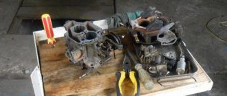
Carburetor repair K-151
Over time, various breakdowns can occur with the carburetor, because all its elements have their own resource. Most often, a faulty K-151 unit provokes increased fuel consumption and reduces the dynamic performance of the vehicle. There are often cases when black smoke pours out of the exhaust pipe, and the car refuses to pick up speed at all. All these problems with the car in most cases are caused by a malfunction of the fuel system. The operation of the K-151 is greatly affected by various deposits that interfere with the normal operation of the jets. You can check their condition and clean the jets quite simply, but to do this you need to disassemble the carburetor itself.
Let's disassemble the mechanism
It is advisable to completely disassemble the assembly in cases where there are no other possibilities to get to any structural element. To check the condition of the jets and clean them, simply remove the top cover of the housing. You can carry out all the work quickly and efficiently with the help of an arsenal of the necessary tools.
The procedure for completely disassembling the K-151 carburetor is as follows:
- Remove it from the cotter pins by unscrewing the four nuts.
- Clean the housing from dirt and dust.
- Loosen the seven cover screws.
- Remove the special cotter pin and rod.
- Loosen the two float chamber screws.
- Remove the econostat sprayer.
- Turn the seats of the needle valve with the horn to “12”, and unscrew the screw of the filter fittings to “22”.
- The fuel filter is removed along with the gaskets, after which the float chamber itself is dismantled.
Further disassembly of the K-151 involves dismantling the air and fuel jets, the idle speed unit, the accelerator pump and removing the quality screws. The carburetor must be completely disassembled at the time of its comprehensive flushing. Most auto mechanics prefer to completely replace the jets with new ones. For these purposes, you can use the jet table. But it is worth saying that they fail only in exceptional cases. Often, washing and blowing them is enough to restore their previous functional properties.
Assembling and connecting hoses
When assembling the unit, you must be extremely careful
It is important to remember the order in which the mechanism is disassembled and during assembly proceed in the reverse order. All elements should be installed in place and securely fastened
Initially, quality screws and two screws are screwed into the empty housing to secure the throttle valves.
Old or new jets are screwed into the sockets, the fuel block and idle are connected. After which the float chamber is installed and secured
It is important not to forget to replace the float and needle itself. Many domestic drivers are also faced with the need to connect carburetor hoses K-151 to ZMZ-402
The photo shows a diagram of the K-151 carburetor.
All hoses and tubes are connected in the following way:
- The largest fuel supply pipe is connected to the float chamber.
- A fuel return hose is connected to the lower outlet of the carburetor.
- Smaller diameter hoses are connected to the economizer and to the throttle valves.
- Then the vacuum hose is connected.
- The forced ventilation hose is connected to the top terminal of the carburetor.
Connecting the hoses is a fairly simple and easy job. But a beginner can easily get confused about their purpose, so at the first stage it is recommended to leave the corresponding markings on their surface with a marker while disassembling the carburetor. By taking simple steps to clean the carburetor parts, you can significantly extend not only the service life of the K-151, but also the main power unit of the car.
Repair
During the operation of the car, various malfunctions may occur in the carburetor; the main signs of malfunctions in this device are:
- increased fuel consumption;
- black smoke from the muffler pipe, it is especially noticeable if you press the gas pedal sharply;
- unstable operation at idle, the engine may also stall when the speed is reduced;
- poor car dynamics;
- failures when accelerating.
If the carburetor is faulty, the engine may not develop speed, and popping noises and shots from the muffler are often heard in the intake manifold. K-151 is a rather complex unit, and almost any element of it can fail.
There are reasons why a carburetor most often fails:
- jets, fuel and air channels become clogged;
- heating causes deformation of the body;
- the float chamber shut-off valve stops working;
- Over time, the jets wear out.
Many repairmen, when restoring the functionality of the carburetor, first of all try to replace the jets, believing that because of them fuel consumption increases and the engine runs unstable
One rather important note - the jets wear out very rarely, and most often wear occurs when the carburetor is often operated in dusty conditions. The most common reason for poor carburetor performance is its clogging, but in order to thoroughly clean the unit, it is necessary to completely disassemble it
Repair of the K-151 carburetor is carried out with the removal of the device, complete washing and purging of all its parts.
Tuning
A simple modification can optimize its operation and significantly extend its service life. To do this, perform the following operations on a cold engine.
The fuel nozzle plug is unscrewed from the carburetor.
The jet itself is removed from the socket using a thin copper wire.
The jet is removed from the solenoid valve.
The hole in the nozzle increases by 0.05–0.1 mm, depending on the modification.
The modified jet is screwed onto the valve.
The removed device is returned to its place.
Increasing the flow rate of the jets improves vehicle dynamics
In this case, it is necessary to replace the rubber valve seal. The solenoid valve gasket is the most vulnerable point of the K-151 series carburetors.
Increasing the capacity of the fuel nozzle will significantly improve the dynamics of the car.
The air jet can be modified in the same way.
Idle systems
K-151 have an autonomous idle system, which is a miniature carburetor. The throttle valve is almost completely closed at this time, the gap between it and the walls is minimal; this should not create a vacuum in the tube of the vacuum ignition timing regulator. The autonomous system ensures good atomization of fuel and uniform distribution of the mixture among the cylinders (by composition), which allows the air-fuel mixture to be leaned to a ratio of 1:15. As a result, it is possible to reduce the concentration of CO in the exhaust gases to 0.3–0.6% (usually regulated with a certain margin - 0.7–1.1%), and CH to 180–230 ppm. Regulation is carried out mainly with the mixture quality screw.
In forced idle modes, including engine braking and slowing down the crankshaft, the membrane mechanism displaces the forced idle economizer valve until it stops, closing the outlet and stopping the fuel supply. The use of an autonomous system with EPH reduces CO and CH emissions by 30–40% and, when tested in the urban cycle, reduces fuel consumption by 4.5%, and also increases engine braking efficiency by approximately 25% (these are “official” or “textbook” values effectiveness of EPHH - Ed.). EPHH also performs the “anti-diesel” function, i.e. With low-octane gasoline, self-ignition is prevented after the ignition is turned off.
In K-151, fuel from the main metering system channel rises to the emulsion tube with fuel and idle air jets. Having passed through the side holes in the tube and the emulsion jet, it is mixed in the form of a fuel-air emulsion with additional air entering through the second air jet. To ensure stability of the mixture composition when regulating the quantity with a screw in the lower part of the carburetor body, the idle system has two channels. According to the first of them, the emulsion enters the cavity in front of the vias through the adapter sleeve, and then through the cross section, adjusted by the lower quality screw, into the main diffuser with the quantity screw. Through the second channel in the carburetors of the first releases, the emulsion passed through a cross section controlled by an additional (upper) quality screw. In the latest arburetors, this screw is replaced by a metering hole in the channel. Next, the emulsion enters an additional diffuser in the throttle body.
The EPHKH K-151 valve control system (for “402” engines - Ed.) consists of an electronic unit that turns on an electro-pneumatic valve when the crankshaft speed decreases below the set one and turns it off when they increase above 1,500 rpm, and microswitch. In the operation of any carburetors, the greatest number of failures occurs in the idle system. This is not surprising - after all, its fuel nozzle has a very small cross-section. Therefore, if the idle speed “disappears”, then it is the first candidate for purging. True, before disassembling the carburetor, it makes sense to carry out simple diagnostics.
You need to remove the wire ends from the microswitch and close them. If the engine starts, it means the electronic unit has failed. Temporarily, until it is replaced, you can drive by insulating the shorted wire tips. If the engine does not work even after closing the tips, remove the hose coming from the throttle body and connect it directly to the EPHH membrane mechanism. The engine starts idling, which means it is necessary to replace the solenoid valve. If the engine does not work again, then it is necessary to remove the diaphragm mechanism cover and check whether the valve moves freely and whether the diaphragm is not torn. If the diaphragm is torn, you can cut off a piece of the hose, cut it lengthwise, slide it under the diaphragm and put it on the valve stem. If the engine is unstable or stalls during the initial period of opening the throttle, then adjust or replace the microswitch. It should close the contacts at the very beginning of turning the throttle lever.
The electronic unit can be checked by connecting to it, instead of the wire going to the electro-pneumatic valve, a light bulb with a power of no more than 3 W. The other wire from the light bulb is connected to ground. The wire from the microswitch must be disconnected. When the speed increases above 1,200–1,500, the light should go out, and when it drops to 900–1,000, it should light up again. In this case, the block is OK.
Blog about UAZ
About the book: Guide. Edition 2003. Book format: pdf file in zip archive Pages: 76 Language: Russian Size: 9.3 mb. Download: free, without restrictions and passwords
Carburetor K-151. Device, adjustment, repair.
The book examines the design and operation features of automobile carburetors of the K-151 family produced by PEKAR OJSC. The main characteristics and parameters of carburetor components and systems are given. The features of operation and maintenance of carburetors and related vehicle systems - forced idling economizer and toxicity reduction - are outlined.
Recommendations for detecting and eliminating typical faults are given. Provides instructions for disassembling, assembling, diagnosing, adjusting and repairing carburetor components and systems. Color illustrations contribute to a better understanding of the material.
Carburetors of the K-151 series are made according to general standard designs, but in design they are fundamentally different from the widely used carburetors of the Weber, Ozone and Solex types and have practically no common parts with them. The need to create carburetors of the K-151 series is caused by the expansion of the model range of the Gorky and Ulyanovsk Automobile Plants, the cars of which are equipped with engines from the Zavolzhsky Motor Plant (ZMZ).
Compared to previous models of carburetors of OJSC PEKAR, carburetors of the K-151 series provide better mixture formation and accurate fuel dosing in all operating modes, which sufficiently meets the requirements of existing and future exhaust gas toxicity and fuel efficiency standards.
OJSC PEKAR produces the basic carburetor of the K-151 series and seven of its modifications - K-151V, 151G, 151E, 151I, 151D, 151P and 151N, intended for installation on four-cylinder ZMZ engines of GAZ cars, UMZ - UAZ cars and UZAM - cars Izh.
All modifications of carburetors of this family are of the same type: two-chamber, two-diffuser with a falling flow of the combustible mixture and pneumatic fuel braking, a balanced float chamber, elements of a closed crankcase ventilation system and sequential opening of the throttle valves. They differ mainly in calibration data and sets of additional elements.
Carburetors of the K-151 series are equipped with a single-section float chamber with a hollow brass float; autonomous idle system (ASXX); main dosing systems in the primary and secondary chambers, transition system of the secondary chamber; control vacuum selection systems for the vacuum corrector of the ignition distributor and exhaust gas recirculation valve (not on all modifications); valve for shutting off the fuel supply in forced idling mode (FID); mechanical drive of the throttle valve of the secondary chamber; diaphragm mechanism for starting and warming up a cold engine with a manual air damper drive; econostat; diaphragm accelerator pump.
Modifications K-151V and K-151G are designed for engines of the UMZ-417.10 family with a displacement of 2.45 liters. UAZ-31512, 31514, 3741, 3962, 2206, 3303, 3909 cars. They differ from the base carburetor, and from all other modifications of the family, in calibration data, the presence of an electrically driven float chamber unbalance valve, the absence of fuel return fittings and control vacuum selection for EGR valve.
Both modifications have the same calibration data and differ only in the design of the throttle valve drive: the K-151V modification has a lever installed on the axis of the throttle valve of the primary chamber for connecting to the accelerator pedal using a rod system; the K-151G has a sector for connecting a flexible cable instead of a lever.
Design and principle of operation
In principle, the design of the K151 carburetor is not much different from Ozone. A two-barrel carburetor consists of three main parts: the cover or upper zone, the body or middle zone and the throttle part, the bottom. Each of them has unique parts, systems and components:
- air damper, ventilation valve, start spring, bracket (intended only for the K-151N model), cover gasket and pneumatic corrector assembly;
- intake valve or ball, float, fuel filter, fitting assembly, nozzle, diffuser and accelerator pump system;
- exhaust gas ventilation fitting, throttle valves, emulsion tubes, textolite gasket and EPHH unit.
It will also be useful to consider some of the features of this carburetor:
- the air throttle is opened using a stepped lever;
- the standard mixture quality screw is periodically unscrewed, so it is recommended to put thick rubber on it or coat the head with silicone glue;
- the ball of the suction valve of the acceleration system is a rare commodity in stores, so it is not recommended to lose it - it is located under the limit screw;
- The neutral control unit may freeze during operation, especially in winter.
Malfunctions and their elimination
Freezing of the economizer housing
The K-151 carburetor on some engines has one unpleasant feature. In humid subzero weather, the fuel mixture in the carburetor actively condenses on its walls. This occurs due to the high vacuum in the channels at idle (the mixture moves very quickly, which leads to a decrease in temperature and the formation of ice). The economizer body freezes first, since air enters the carburetor from here, and the flow cross-section of the channels here is the narrowest.
The trunk of the air intake hose can be thrown directly to the manifold. Or make a so-called “brazier” - a heat shield made of a metal plate, which rests on the exhaust pipes and to which the air vent hose is connected (see figure).
"Brazier"
Also, in order to reduce the risk of the economizer freezing problem, before the trip we warm up the engine to an operating temperature of 60 degrees. Despite the thermal insulation gasket from the engine, the carburetor still receives some heat.
Flange straightening
With frequent disassembly and removal of the carburetor, as well as with excessive force when tightening the flange to the engine, its plane may be deformed.
There are many ways to solve this problem. But the simplest and most accessible method is the following:
- We heat the plane of the carburetor flange using a gas burner. First, we remove all the components and parts of the carburetor (fittings, levers, etc.).
- Place the plane of the float chamber on a flat surface.
- As soon as the carburetor heats up, place a thick, even piece of hard metal on top of the flange. We don’t hit the piece too hard, moving it to different places each time. Basically, the bending of the flange occurs along the edges, in the area of the bolt holes.
Useful video
For more information about the method of straightening a flange, we recommend watching this interesting video:
To prevent further bending of the flange, simply tighten it evenly once to the engine and do not remove it again. As we saw above, the carburetor can be cleaned and adjusted without removing it from the engine.
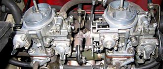
Gazelle
Model ZMZ 40524.10 is a gazelle carburetor known to everyone. The car brand “Gazelle” is one of the most popular and affordable trucks in Russia, which were originally intended for transporting not very large loads. Due to the huge number of such machines, we will consider several nuances of different gazelle systems. For example, a microprocessor ignition system, which is installed on the 406 model.
If the driver claims that his car makes some popping noises, jerking noises and loses its power. In this case, the power system, engine and ignition system should be checked. We checked the carburetor with a gas analyzer not during the operation of the 1st and 2nd chambers, cutoff, enrichment and during idling and did not find any violations. Next they check the engine. When checking the compression, no problems were identified, but the next time deviations from the norm were detected. It was concluded that the jerks and pops that the driver did not like were due to the jumping of the teeth of the upper chain.
Carburetor ZMZ 406 series
What to do if a gazelle loses power?
From the very beginning, you need to check how the diagnostic circuit and the on-board diagnostic system function, because when the travel image mode is activated, a malfunction code of 12 should be obtained. To read the code, the 10th and 12th contacts of the diagnostic block must be closed. Using a diagnostic toaster, engine sensor parameters are measured and then compared with typical values for average engines. The most common reason for a decrease in car power is contamination of the tube that connects the intake manifold and the pressure sensor.
Gazelle ignition system
The microprocessor ignition system ignites the working fluid in the cylinders and sets the required vehicle ignition timing for all engine modes. The ignition system performs the function of regulating the operation of the forced idle economizer. Thanks to the ignition system, engine operation becomes more economical, compliance with all exhaust gas toxicity standards is monitored, detonation is eliminated and the vehicle's power is increased. If we compare the classic system with this one, then this ignition system is much more reliable and durable. Here only the spark plugs can wear out.
Table: types of modifications of K-151 carburetors
| Model | Cars | GDS fuel nozzle dimensions | GDS air jet dimensions | Diffuser diameter, mm |
| K-151 | Volga GAZ-2410, -31029, 3102, 3110; Gazelle GAZ-33021, -33023, -33027, -2705, -27057 | 225/380 | 330/330 | 23/26 |
| K-151V, K-151G | UAZ-31512, -31514, -3741, -3962, -2206, -3303, -3909 | 225/330 | 330/230 | 23/26 |
| K-151D | Volga GAZ-3110 ZMZ-406; Sable GAZ-2752, -2217, -22171; Gazelle ZMZ-406 (except GAZ-33021) | 225/340 | 330/330 | 23/26 |
| K-151E | UAZ-3153, -33036, -39094, -39095 | 230/330 | 330/330 | 23/26 |
| K-151I | Volga GAZ-31029; Gazelle GAZ-3302 | 225/380 | 330/330 | 23/26 |
| K-151L | UAZ-31601 | 225/340 | 330/330 | 23/26 |
| K-151N | IZH-412IE, -21251, -2715-01, -27151-01 | 225/330 | 330/230 | 23/26 |
| K-151P | IZH-2126 Oda | 225/330 | 310/280 | 23/26 |
| K-151S | Volga GAZ-3102, -31029, -3110 ZMZ-402.10; Gazelle; Sable | 205/330 | 260/330 | 23/26 |
| K-151T | Gazelle UMZ-4215.10 | 235/330 | 280/330 | 23/26 |
| K-151U | UAZ-31512 ZMZ-402.10 | 225/380 | 330/330 | 23/26 |
| K-151TS | UAZ-33036, -31512 | 205/280 | 260/330 | 23/26 |
- https://vsekarby.ru/avtomobili/legkovye/karbyurator-k-151-regulirovka-remont.html
- https://swapmotor.ru/ustrojstvo-dvigatelya/karbyurator-k151.html
Service
Carburetors are reliable and unpretentious devices. K-151, like other components in the automotive system, requires periodic maintenance. Basically, problems arise in the event of unqualified intervention in its design or due to inappropriate maintenance. Neglecting the simplest maintenance procedures for the K-151, it may happen that the carburetor ceases to function fully due to the clogging of the calibrated holes with hard tarry deposits. For its correct operation, it is necessary to timely adjust the main systems.
Idle speed adjustment
The design of the K-151 does not allow dirt and dust to penetrate directly into the unit; in addition, during its operation, due to the movable joints, self-cleaning of the most important functional elements occurs. A simple but extremely effective layout allows even a dirty K-151 carburetor to work no worse than an absolutely clean copy. But at least 1-2 times a year you should clean it from the outside using compressed air. This is the minimum required maintenance for the device. Don't forget about adjusting the most important systems.
Adjusting the XX on the K-151 carburetor is necessary for normal engine operation. A properly operating engine contributes to the formation of a minimum amount of carbon monoxide in the exhaust gases. Since most car enthusiasts do not have even the most ordinary gas analyzer at their disposal, monitoring the operation of the system is not so easy. But there is a way out of this situation - it’s enough to arm yourself with one tachometer.
The procedure is as follows:
- Initially, the engine warms up, then the quality screw rotates until the maximum idle speed is established. In this case, the quantity screw remains in the same position.
- Afterwards, the speed is set to exceed the initial value by 100-120 rpm.
- It is recommended to do the above steps twice to be on the safe side.
- Then the quality screw is tightened until the speed reaches a normal value.
It is especially effective to adjust the idle speed if you have a high-precision tachometer. Such work can be carried out at any time, but it is most advisable to do it two or three times within one year.
Adjusting the float mechanism
Any carburetor adjustment must include adjusting the float mechanism - a responsible and extremely important task. But no difficulties in carrying out such work should arise even for those who have only recently become owners of a car with a carburetor power system. However, it is worth understanding that any inaccuracies in the adjustments can lead to further interruptions in the operation of the power system
That is why it is important to prepare thoroughly before starting to manipulate this mechanism.
Procedure:
- The upper part of the housing is removed.
- About a quarter of the fuel is pumped out.
- The crankshaft is installed in such a position that nothing interferes with the movement of the fuel pump diaphragm.
- Gasoline is pumped in manually.
- Once the required fuel level is set, the shank of the caliper with the height set at 21.5 mm is lowered between the wall and the shut-off needle.
When adjusted, the shoulders of the caliper will rest against the top of the body, and the shank will come into contact with the fuel. At a low level, the tongue must be bent upward, and at a high level, accordingly, downward.
It is important to drain the fuel from the chamber each time after changing the position of the tongue.
see also
Comments 20
What is the difference between carburetors C and E? Judging by the plate, the UAZ needs E. Why did they put C?
I don’t remember about E, but this 417 internal combustion engine, in theory, needs B, but they only differ in the jets and some modifications. I looked and searched a lot, and decided to stop at S. I’ve forgotten now. In general, I want to try K126...
Or maybe I just haven’t driven a UAZ, and it seems that it drives poorly... And this happens)) But putting a ruler in 151 is unnecessary)) if the carburetor is horizontal (judging by one of your photos and I see that the carburetor is “rolling” ) then just look at the protrusion in the PC (where you rested the ruler), then this protrusion should be submerged by 0.5-1 mm Now a little about the “carburetor roll”, as is known from numerous sources on carburetors not only of the 151 series, the fuel level is checked on the horizontal the plane where the car is rolled out, in this case all sides of the PC flange are horizontal, taking into account the tilt of the internal combustion engine. It also happens, as in your case - “carburetor roll”, there are many reasons for this, one of them is replacing the intake manifold, etc. then the level should not be measured in the generally accepted place, exactly where you measured, but should be measured at the walls of the EC.
Run the engine in, and then check the dynamics.
Yes, it’s already 600 km. drove... I don’t give it much, I don’t drive under load, above 3000 rpm. I’m not cool... Sometimes there are only 3500 ladies...
3000 minimum, then it will fly. What is the compression on the cylinders?
I measured it 200 km ago, 11 in all.
Great. So take it easy. For me, 3500 and even 3000 rpm. a lot for him. Speed range max. torque for this engine is 2000-2500 rpm. Stick to this range.
Well, not much, but in 4th, to accelerate to 80, you need at least 3000
Well, don't speed up to 80 
So, it’s hard to drive slowly in the city...))
Well, not much, but in 4th, to accelerate to 80, you need at least 3000
Yes, the specifics of the checkpoint
Moreover, the bridges are military, and the tires are standard. Once I get rich with 35-37 wheels, it will be better, I won’t have to turn the engine at 3000 rpm at 80 km/h...
Yes, it’s already 600 km. drove... I don’t give it much, I don’t drive under load, above 3000 rpm. I’m not cool... Sometimes there are only 3500 ladies...
We need to drive 15,000 km! then it will be run in)
cool video! I didn't know you could test carb this way))
It only spits a little gasoline...))
What I like specifically about the 151s is that the float is not made in the cap, that the XX system is separate from all other carburetor systems... The EPHH valve is external, not like on Solexes it is screwed into the carb, here you can install any valve...
There are also disadvantages to this arrangement of the fuel valve in the video, this is clearly visible, you can see how the fuel gushes out, as a result, fogging of the front part of the carburetor can be cured. I usually solder a brass screen onto the float lever, cleverly bent in the form of a horseshoe-shaped plate that faces downwards
Well, basically, if the carb cap is tightly screwed on, then let it gush, I think it’s not scary... But to understand how you made the float so that it doesn’t gush, you should look at the photo, it’s not entirely clear... But this is useful if you drive with an open carb ... )))
It’s good that the main thing is screwed on well without fanaticism, and even in this situation, no one has canceled the capillary effect)) But there is no photo of the screen ((
The K-151 series carburetor is produced by the domestic enterprise Pekar. It meets all modern standards, ensuring reliable operation of vehicles of any kind. However, like any other component of the car, the carburetor periodically needs maintenance and repair.