The electrical equipment of any car is not complete without fuses (fuse links) and the VAZ 2107 is no exception. Thanks to these elements, electrical wiring is protected from damage in the event of improper operation or failure of a particular consumer.
- Fuse box VAZ 2107 injector and carburetor
Where is it located?Old version of the block
- Table: which fuse is responsible for what
- New sample block
- Video: how to remove the fuse box on a VAZ 2107
- Repairing a broken track
- How to remove the power supply
Location of relay and fuse boxes
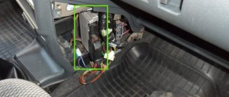
The location of the VAZ 2107 fuses and relays is located in the engine compartment, its article number is 2107-3722020-10. It is in an accessible location. In injection cars, an additional relay and fuse block is installed that serves the engine's electronic control unit. It is located under the glove box.
In cars of early years of production, the main relay and fuse box has a different design and arrangement of elements.
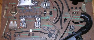
Electronic ignition design
To install a contactless system on a “classic” VAZ 2107 with a carburetor, it is advisable to study how it works. This will help you correctly assemble the circuit and successfully put it into operation. BSZ for old carburetor Zhiguli models consists of the following elements:
- distributor, also known as the distributor of the ignition system;
- high-voltage coil of a new design (different from the old one, which works with mechanical contacts);
- switch responsible for system management;
- high-voltage and ordinary wires with connectors and terminals connecting the listed elements;
- spark plug.
Reference. Since the new ignition system does not have a contact group, and its operation is controlled by an electronic unit, the names “contactless” and “electronic” are equally suitable for it.
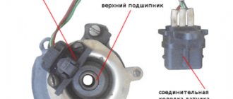
Elements of the electronic ignition system of the VAZ 2107
The new high-voltage coil has 2 windings. The primary one is made of a large cross-section conductor and is connected to the vehicle's electrical network through the ignition switch relay. The secondary winding is wound with a large number of turns of thin wire and connected by a high-voltage wire to a distributor consisting of the following parts:
- a housing with a centrally mounted shaft;
- a movable contact (the so-called slider) is fixed at the end of the shaft;
- A cover is placed on top of the body, where high-voltage large-section wires leading to the spark plugs are connected;
- there is a protrusion (cam) on the shaft, opposite which there is a Hall sensor;
- a vacuum diaphragm is attached to the side, providing ignition advance.
The switch is connected by small cross-section conductors to the distributor and coil; its task is to control the timely supply of sparks to the spark plugs.
Reference. In newer modifications of the VAZ 2107, where there is an injector instead of a carburetor, there is no separate switch. There is no need for it, since the on-board computer controller is in charge of spark generation and fuel supply.
Connection diagram of contactless system elements
Numbering, ratings and purpose of fuses
Each of the fuses in the VAZ 2107 can serve one or more electrical circuits of the car. If a fuse fails, a specific device or vehicle system (or several) will not receive power. As a result, a particular device becomes inoperable.
Fuse failure is not always the cause of a malfunction. In many cases, a blown fuse is the result of a component or system malfunction. Such cases include:
- short circuit in the car's electrical wiring;
- burning of contacts and connectors;
- wear of the fuel pump, electric motors of vehicle system drives (windshield wiper, fan);
- malfunction of the electronic engine control unit.
In the event of a failure of any of the vehicle systems, according to the table below and the fuse location diagram, determine the fuse number and its location in the block. If this fuse is responsible for several systems, you should check the functionality of the other system. If it works correctly, the fuse is most likely good and is not the problem. After this, using a multimeter or other measuring equipment, the functionality of the fuse is checked by measuring its resistance (continuity).
Testing the fuse should only be done on a dismantled (removed) fuse. The resistance of a good fuse is close to zero. In most types of fuses, the thread of its working area is visible through the light or is located outside the body part. You can check the fuse visually, but there are often cases of erroneous inspection when the working area has a microcrack.
Fuse box VAZ 2107
The missing relays are not used or have been moved, for example, the relay for turning on the engine cooling fan is on a strip with additional relays in the passenger compartment.
Table 1. Purpose of fuses VAZ 2107 (under-hood unit):
VAZ 2107 fuses, which one is responsible for what
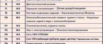
Explanation of fuses
The explanation of fuses and the circuits they protect is summarized in the table below.
| Fuse designation | Fuse rating, A | Protected circuits |
| F1 | 8 | Reversing lights. Electric stove motor. Signal light and rear window heating switch (winding) |
| F2 | 8 | Windshield wipers and washers. Headlight brushes and washers. Windshield wiper switch. Relay for wipers and headlight injectors (contacts) |
| F3 | — | Spare |
| F4 | — | Spare |
| F5 | 16 | Rear window heating mesh and switch (contacts) |
| F6 | 8 | Cigarette lighter. Carrying electrical socket. Watch. front door open warning lights |
| F7 | 16 | Sound signal, signal stick. Electric motor engine cooling fan and electric motor switch (contacts) |
| F8 | 8 | Turning lights in emergency mode. Switch and relay switch for turn signals and emergency lights |
| F9 | 8 | Generator field winding |
| F10 | 8 | Turn lamps in turn indication mode and the corresponding indicator lamp. Relay for turning on the fan motor (winding). Control devices. Indicator lamp and battery charge control switch. Monitoring fuel reserve, oil pressure, parking brake and brake lining wear, brake fluid level. Handbrake warning lamp relay-breaker Carburetor pneumatic valve control system |
| F11 | 8 | Brake light bulbs. Interior light |
| F12 | 8 | Right headlight (high beam). Coil of the relay for turning on the headlight cleaners (with the high beams on) |
| F13 | 8 | Left headlight (high beam). High beam headlight control |
| F14 | 8 | Dimensions of the left headlight. Dimensions of the right rear light. License plate lights. Engine compartment lamp. Control for turning on the parking light |
| F15 | 8 | Right headlight size. Left rear light bulb. Cigarette lighter light bulb. Instrument lighting lamps. Glove box light |
| F16 | 8 | Right low beam lamp. Winding of the switch for turning on the headlight wipers (with the low beam on) |
| F17 | 8 | Left low beam headlight bulb. Rear fog lamps*. Control for turning on fog lights* |
Designation in the table: * Since 1988, protected by a separate fuse mounted in the wire near the fog light switch.
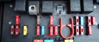
Relay on fuse box
The fuse block relays and the VAZ 2107 relays are located in the same fuse block. Their purpose:
- Rear defroster relay.
- Relay for washer and headlight cleaner.
- Power supply for sound signal.
- Cooling system electric fan relay (up to 2000).
- High beam relay.
- Low beam relay.
Checking the serviceability of the relay can be done using a multimeter. To do this, it is necessary to test the armature winding. Its resistance usually ranges from 50 to 200 ohms. It is safer to test connect the winding to the vehicle's on-board voltage. To do this, the relay must be removed from the relay and fuse block. If one terminal of the winding is connected to the positive terminal of the battery, and the other to the negative terminal, you should hear a characteristic click of the activated relay. The main causes of relay malfunction:
- burning of contacts;
- break or burnout of the relay winding;
- sticking of contacts.
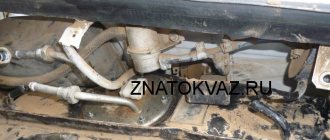
Cooling fan relay VAZ 21074 injector location
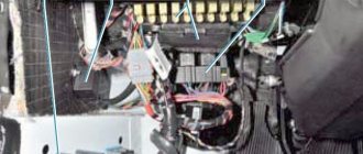
The fusible elements are located on a kind of electronic board, which is located under the hood of a VAZ car. Switching relays are also located there. If you open the hood, you can see that the mounting block (both old and new) is located near the windshield directly opposite the passenger seat.
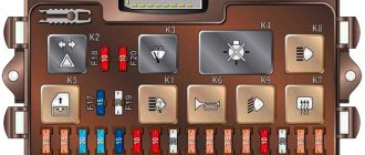
Old style mounting block
Old-style mounting blocks are installed only on carburetor cars. Although a new model can be installed on the carburetor. The old unit is equipped with 17 fuses. Each element is responsible for protecting one or more circuits. Each element is responsible for protecting one or more circuits.
Let's consider the purpose of each relay. The leftmost relay is responsible for switching the rear window heating circuit. The second relay on the left is designed to control the circuit of headlight cleaners and washers (this element is not present in all models). The third element is designed for switching audio signal circuits. The purpose of the fourth socket (it is empty in the photo) is to switch the cooling system fan motor circuit. For example, VAZ 2107 cars produced after 2000 do not need this element. The last two relays are necessary to control the circuits of the high and low beam lights.
New mounting block
Some VAZ 07 model cars are already equipped with new type mounting blocks. The new “sevens” are equipped with a box of similar size, only with modified fusible elements. The purpose of the relay is similar to the old model. Both devices perform the same functions, but they differ in shape, location, and type of elements.
Injector
There are carburetor and injection models of the VAZ 7 model. Injection ones are more common today. The essence of the process is that gasoline is supplied under pressure into the fuel rail, in which it is mixed with purified air in a ratio of 14 to 1. When the valve opens, the mixture enters the combustion chamber unhindered (since it is always under pressure). Ignition occurs and the piston makes a power stroke. At the same time, the crankshaft rotates and the car is set in motion.
Various sensors are responsible for the operation of all components, which measure temperature, pressure, amount of air and gasoline. All signals are sent to the microcontroller control unit. It contains a special algorithm that regulates the operation of all main components and mechanisms.
Electrical circuit diagram
Schematic diagram of the relay and fuse box, enlarged:
Electrical diagram of the relay and fuse box VAZ 2107
This diagram is useful in cases where the failure of the vehicle's power supply circuits is not associated with a malfunction of fuses and relays, but consists of burnt out tracks or charring of contact areas in the fuse and relay box. Repairing the unit requires high qualifications. Sometimes the cost of repairs is not justified. It is more rational to make an aggregate replacement of the unit (entirely), although the price is quite high (about 2500 rubles).
Although it is given for a car with contact ignition, it is almost identical to the injection version.
Check and replacement
If you suspect that the engine is overheating and there is no sound from the fan for a long time, it is necessary to determine the malfunction. If the wiring is shorted, the device may fail or the fuse may blow.
Checking the device is easy. You need to remove the wiring from the sensor, turn on the ignition key and connect the ends. If the cooling works, then there is a problem with the device and it needs to be replaced. It happens that cooling turns on at temperatures higher than those indicated on the sensor body, which also indicates its malfunction.
To replace it, you will need to drain the antifreeze or rush to screw in a new sensor, spilling a little coolant. The engine must be cold. You can unscrew it with a wrench or an adjustable wrench. It is better to substitute some kind of container and use a wrench to undermine the housing nut. Then carefully unscrew the thread by hand, pressing it against the socket. Move the old device aside and quickly press it with your finger, maybe some kind of plug, on the hole in the radiator. Carefully screw in the purchased sensor and connect the wiring.
Replacing the VAZ 2107 fuse box with a new one
Sequence for replacing the VAZ 2107 fuse box:
- Remove one terminal (or both) of the battery.
- Remove the air filter.
- Disconnect the harness at the bottom of the fuse box.
- Remove the glove compartment cover.
- Disconnect the second harness from the fuse box.
- Remove the two block mounting bolts.
- Install a new fuse box.
- Connect the electrical wiring to the new unit.
- Install the structure in the reverse order.
- Connect the battery terminals (first positive, then negative).
The relay and fuse box is the heart of the vehicle's electrical equipment. The performance of all electrical systems of the machine depends on its proper operation.
The process of replacing a sensor on a carburetor engine
This is where the process may seem more complicated. After all, given that the sensor is located at the bottom, you will have to drain the coolant. And to do this you need to look for an inspection hole, remove the engine protection, etc. But you don’t have to do this. You just need to quickly screw the new sensor in place of the old one. Naturally, some coolant will spill out, but its amount will be limited to 20-30 ml. In addition, you can always place a properly cut plastic bottle under the connection point.
So, prepare a new sensor and a “30” wrench. Disconnect the wires from the device. Carefully unscrew the sensor using the key. Continue unscrewing it by hand, pressing it against the radiator body. When the sensor comes off the thread, you can pinch the hole with your finger and start screwing in the new element with your other hand. Do not manage to lose the O-ring that is placed on the threaded part of the device. That, in fact, is the whole process. All that remains is to connect the wires to it, start the power unit and check if everything works.
Fuel temperature sensor
A malfunction is usually indicated by a warning lamp on the dashboard with the inscription “Check engine”. Temperature sensor:
Note: The information coming from the thermistor is used by the PCM for diagnostic purposes. Failure of the sensor leads to the recording of a corresponding malfunction code in the OBD system memory. Performing the procedure described below will result in a fault code being stored in the OBD permanent memory, which will be illuminated by the “Check Engine” warning lamp on the instrument panel. Once you have completed the check and related repairs, clear the system memory.
Fault diagnosis
The indicator on the panel signals you about overheating (boiling) of the engine, but according to external signs, the heating of the engine is quite normal, and there is no sign of boiling, perhaps the sensor (DTOZH) is simply lying. The situation is much worse when the engine “boils”; the indicator on the control panel shows normal temperature, the reason is the same, you just need to wait for the engine to cool down and add fluid (it’s good if you have some in stock). So:
The temperature (heating) indicator of the cooling system fluid on the instrument panel (Photo below) is located in the lower left part.