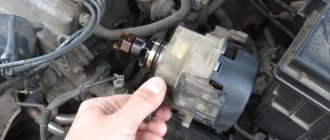
A distributor is a device responsible for producing a spark at the right moment. The part is installed on internal combustion engines. When the piston is at the top point, ignition occurs.
A distributor is a breaker-distributor. Without it, not a single gasoline internal combustion engine can operate. You can find this device on cars such as:
Without a distributor, the timely formation of a spark in the engine cylinders would be impossible.
PURPOSE OF THE DEVICE
One of the most important subsystems of a gasoline engine is the ignition system. The fact is that normal operation of the engine is possible only if the combustion of the fuel-air mixture occurs in a timely manner. Otherwise, the entire work algorithm is disrupted.
During operation of the device, voltage is generated. It is served on candles. It is on them that the spark necessary to ignite the mixture is formed. As a result, the engine starts working and the car moves in the right direction.
For all the processes described above to become a reality, a distributor is needed. In this system it performs the following functions:
- Acts as an initiator of spark formation. This occurs due to the opening of contacts.
- The device directs the generated voltage to the desired spark plug.
- The distributor can, if necessary, change the moment of sparking. This parameter is determined by the driving mode selected by the driver. Also, a lot depends on the quality and type of fuel.
- The device is capable of storing energy in a bobbin.
As you can see, the part performs many functions. It is not surprising that without its normal operation, the operation of the engine is impossible.
Questions about choosing and replacing a slider with a resistor
A slider with a resistor filled with compound. A replacement resistor for the slider.
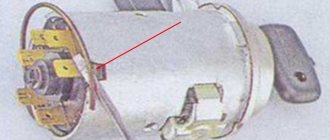
The resistor placed in the slider is subjected to significant electrical and mechanical loads, so over time it can fail - burn out or break (crack). As a rule, a breakdown of the resistor does not disable the engine, but seriously impairs its functioning - the engine does not gain full power, responds poorly to the gas pedal, “troits”, detonates, etc. The fact is that sparks can jump through a burnt out or cracked resistor, so the ignition system continues to work, but with disturbances and less efficiently. If such signs appear, you should first remove the distributor cover (this should only be done with the engine stopped and the terminal removed from the battery), dismantle and inspect the slider. If the slider is ordinary, then it can be removed without a tool, and if the part is connected to the ignition timing regulator, then two screws should be removed using a screwdriver.
If, when examining the resistor, there are no external signs of its malfunction (it is not burnt or broken), or the resistor is filled with compound, then you should check its resistance using a tester - it should be within 5-6 kOhm (for some cars - up to 12 kOhm, but not lower than 5 kOhm). If the resistance tends to infinity, then the resistor is faulty and should be replaced. A replacement part should be of the same type and resistance - this is the only way to guarantee that the resistor will fall into place and the entire system will work normally. Replacing a resistor involves simply removing the old part (it’s easy to pry it off with a screwdriver) and installing a new one. If the resistor is filled with compound, then you will have to change the entire slider - for domestic cars such a replacement will cost several tens of rubles.
Often, car owners install wire jumpers instead of resistors - this is strictly prohibited. The absence of a resistor increases the level of radio interference and can disrupt the operation of the ignition system (including leading to intensive wear of the contacts of the slider and distributor cover, and spark plug electrodes). It is also not recommended to replace a slider with a resistor with a simple slider in ignition systems with high-voltage wires of zero resistance. For replacement, only those types and models of runners recommended by the ignition distributor manufacturer should be used.
With the correct selection and replacement of the slider with a resistor (or just the resistor), the ignition system will work reliably and with minimal radio pollution.
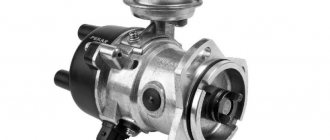
Distributor design
The distributor circuit assumes the presence of such elements as:
- low voltage current breaker;
- high voltage current distributor;
- centrifugal ignition timing regulator;
- vacuum ignition timing regulator.
The distributor circuit is designed so that at a certain moment the breaker opens the primary ignition circuit, as a result of which a high voltage current is created in the secondary winding of the ignition coil. Through the distributor, this current is transmitted to the spark plugs in certain cylinders. The regulators automatically adjust the ignition timing, which depends on the current operating mode of the engine.
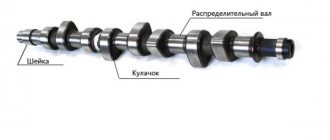
The distributor breaker is an electromechanical part and consists of the following parts:
- shaft;
- movable contact plate;
- movable contact plate;
- capacitor;
- frame.
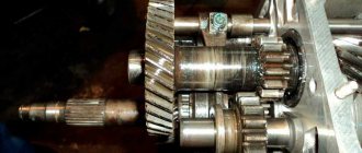
The breaker shaft consists of two main parts. On one of them, depending on the type of breaker, cams are installed, the number equal to the number of cylinders in the engine. This distributor device is not very reliable, since a large number of contacts, as well as the presence of moving parts, lead to regular problems with this unit.
The distributor device, as well as its use in general, are outdated from the point of view of modern electrical equipment, but in our country there are still a lot of carburetor engines, so the problem of the performance of this unit is currently relevant.
As for where the distributor is located in the car, most often it can be found under the hood next to the engine, near the cylinder head or on it. Although the exact location of the node depends solely on the model of the machine.
Repair of VAZ 2109 distributor
One of the most common problems with the VAZ 2109 distributor is failure of the Hall sensor. If the sensor is faulty, the engine stops starting; we replace this part as follows:
- remove the distributor from the engine;
- unscrew the cover (two screws);
- dismantle the vacuum regulator;
- unscrew the screw holding the sensor connecting block;
- unscrew the fasteners of the upper bearing holder, it is secured with two screws;
- remove the bearing assembly with the sensor, remove the Hall sensor from the holder (two screws);
- we install a new part, assemble the distributor, and put it in place.
After repairing the VAZ2109 distributor, you may need to adjust the ignition; it is done very simply:
- loosen the three nuts of the PR housing itself;
- with the engine running, gradually turn the distributor in one direction or the other, apply gas with the throttle - we find the position in which the engine picks up speed faster, without dips;
- Then we tighten the nuts and check the car while driving. If it was not possible to find the desired position immediately, repeat the operation.
Operating principle of the distributor
In many ways, the operating principle of the distributor remained unchanged for many years. In VAZ cars, such as VAZ 2109, 2106, 2107, 2108, an ignition system of this type was used almost until the end of the last century.
The basis of the work is the connection of the distributor with the engine crankshaft. When the piston in the first cylinder takes the position corresponding to TDC, the breaker contacts open, a high voltage appears in the ignition coil, directed through a slider located in the distributor cover to the spark plug of the first cylinder.
There the combustion of the fuel assembly occurs, and the crankshaft continues to rotate. In addition to moving the pistons, it causes the breaker cam to rotate. When in another cylinder another piston occupies a position corresponding to TDC, at this moment the breaker contacts in the distributor open again, and a high-voltage voltage is generated in the ignition coil and supplied to the desired spark plug.
This joint rotation of the crankshaft, the breaker cam and the distributor slider ensures that a spark appears where and when needed. However, this does not cover all aspects of how the distributor works. To understand its operation, it is necessary to touch upon such concepts as the angle of the closed state of contacts (UZSK) and the ignition timing angle (IAF)
UZSK
A concept such as UZSK characterizes the time when the breaker contacts are closed. In essence, this is an indirect characteristic of the accumulation of energy in the coil after the completion of spark formation. UZSK directly affects the amount of energy spent on sparking and, accordingly, on engine operation.
In cases where the distance between the contacts is small, the coil will not accumulate the necessary energy and the spark energy will be low, which will lead to interruptions in the operation of the motor. A large gap also leads to interruptions, since the contact breaking time is reduced and the coil does not have time to fully discharge.
Each ignition system has its own optimal UZSK, to ensure which, if necessary, the distributor must be checked and adjusted.
UOZ
This concept concerns the moment of ignition of a fuel assembly. The fact is that its combustion does not occur instantly, and often, to ensure optimal conditions for such a process, it must begin earlier than the piston reaches the TDC position. The OZ characterizes the time by which the appearance of a spark precedes the appearance of the piston in the TDC position.
DETAILS ABOUT THE MOST IMPORTANT ELEMENTS OF THE TRAMBER DEVICE
VACUUM REGULATOR
It is this device that can change the OZ if necessary. As soon as the motor load changes, appropriate adjustments are made to the operation of the distributor device parts.
The vacuum regulator of the distributor is a closed cavity. To ensure better performance, the design is divided by a diaphragm. One cavity goes directly to the carburetor.
When a vacuum occurs, the diaphragm begins to move. As a result, pressure is exerted on the movable disk and the breaker cam. The response time of the latter is adjusted depending on the current situation.
OCTANE-CORRECTOR
This is a very important element in the distributor design. Without it, the entire system could not function normally. The unit changes the SOP depending on the fuel that is currently being used.
By its design, this distributor element resembles two plates with an arrow. The same arrow is installed on the engine. There are special lines on it, through which the ignition angle is adjusted. It is almost impossible to do without this part when refueling different types of gasoline.
Distributor malfunctions
The following signs indicate that the distributor is malfunctioning:
When there is a spark on the central wire, but not on the spark plug wires, this indicates a breakdown of the slider.
- the car jerks periodically when driving;
- Unstable engine operation at idle;
- the engine does not start at all;
- the knocking of the piston fingers is heard while accelerating;
- the speed increase dynamics decreased;
- fuel consumption has increased.
In most cases, the causes of distributor failure are:
Breakdown of the roof and ignition coil occurs due to large gaps in the contacts of the distributor cover and slider, spark plugs and bad candlesticks.
- burnout of the runner;
- oxidation or shorting of contacts under the cover;
- breakdown of the distributor cover;
- failure of one of the sensors;
- problems with the shaft bearing and other problems.
In each of these cases, replacement is required. But at the same time, for almost any car, it is possible to change not the entire distributor, but only its failed part, which is an advantage, since it significantly reduces the cost of repairs.
The most basic check of the distributor is a visual assessment of the condition of the slider, contacts and cover.
In a contactless distributor, the main malfunction is the failure of the hall sensor or inductive sensor.
To check the ignition system and distributor, among other things, observe the spark on the unscrewed spark plug after starting the engine. In garage conditions, you can also check using measuring instruments or indicators.
The distributor capacitor is also one of the parts that often fail. It helps to increase the voltage supplied to the spark plugs when the engine starts. And in order to check it, you need to disconnect it and touch the “ground”, and if a characteristic crackling sound is heard and a voltage drop is observed, the capacitor is working, if this does not happen to the replacement part.
A distributor is always a dismountable unit that can be disconnected, removed from the car, disassembled into components, a problem can be detected and eliminated by replacing the damaged part.
The design and principle of operation of a distributor breaker or distributor - video
Some owners of classic cars of the VAZ 2101-07 family are constantly trying to improve, modify, add electronics and convenience. One of these improvements is the installation of contactless electronic ignition.
Explanation of symbols
Knowledge of the definitions of the 2107 Lada electrical circuit will help you quickly locate the required wire, diagnose it, identify and fix the malfunction. Of course, when replacing the cabin filter or changing the oil, such information will not be useful, but in specialized matters, deciphering the symbols will significantly simplify the repair process.
- 1 – head lights VAZ 2017;
- 2 – side turn signals;
- 3 – battery;
- 4 – starter activation relay;
- 5 – carburetor electro-pneumatic valve;
- 6 – internal carburetor switch;
- 7 – generator system 37.3701;
- 8 – gearmotors for headlight cleaners*;
- 9 – fan motor activation sensor;
- 10 – electric motor of the engine cooling fan;
- 11 – sound signals;
- 12 – ignition distributor;
- 13 – spark plugs;
- 14 – starter;
- 15 — coolant temperature indicator sensor;
- 16 – engine compartment lighting;
- 17 – critical oil pressure indicator sensor;
- 18 – warning lamp for insufficient brake fluid level;
- 19 – windshield wiper electric motor;
- 20 – power system valve control unit;
- 21 – ignition coil;
- 22 – electric motor of the headlight washer pump*;
- 23 – electric motor of the windshield washer pump;
- 24 – mounting block;
- 25 – windshield wiper relay;
- 26 – hazard warning and direction indicator relay;
- 27 – brake light switch;
- 28 – reverse lamp switch;
- 29 – ignition relay;
- 30 – ignition switch;
- 31 – three-lever switch;
- 32 – alarm switch;
- 33 – plug socket for a portable lamp**;
- 34 – heater heater fan switch;
- 35 – additional switch for the heater electric motor;
- 36 – indicator lamp for turning on the heated rear window;
- 37 – indicator lamp for insufficient brake fluid level VAZ;
- 38 – signaling unit;
- 39 – electric motor of the stove fan;
- 40 – glove compartment lighting lamp;
- 41 – lamp switches on the front door pillars;
- 42 – switches for warning lights of open front doors***;
- 43 – alarm lights for open front doors***;
- 44 – connecting block;
- 45 – cigarette lighter;
- 46 – hours;
- 47 – instrument lighting switch;
- 48 – diode for checking the serviceability of the warning lamp for insufficient oil pressure and brake fluid level;
- 49 – fuel level indicator;
- 50 – indicator lamp for insufficient gasoline level (fuel reserve);
- 51 – speedometer;
- 52 – control lamp for turning on the direction indicators on the dashboard;
- 53 – warning lamp for the carburetor air damper opening;
- 54 – indicator lamp for battery charge indicator;
- 55 – switch for signaling that the carburetor air damper is slightly open;
- 56 – instrument cluster;
- 57 – econometrician;
- 58 – lamp switches on the rear door pillars;
- 59 – coolant temperature indicator;
- 60 – tachometer;
- 61 – handbrake indicator lamp;
- 62 – low oil pressure indicator sensor;
- 63 – indicator lamp for high beam headlights;
- 64 – signaling device for turning on dimensions;
- 65 – voltmeter;
- 66 – parking brake warning switch;
- 67 – external lighting switch;
- 68 – rear window heating switch;
- 69 – rear fog light switch with on indicator*;
- 70 – fog light circuit fuse;
- 71 – interior lighting lamp****;
- 72 – rear lights;
- 73 – fuel level indicator and fuel reserve sensor;
- 74 – pads for connecting to the rear window heating element*;
- 75 – license plate lights.
Which ignition is better: contactless or contact?
Contact ignitions are obsolete, but are still used in older cars. On rear-wheel drive VAZ models, contactless was first installed on 2107.
Let's look at the differences between contact and non-contact ignition:
Advantages of contactless ignition:
- since there is no contact group in the distributor, sparking occurs clearly;
- long coil life;
- at medium engine speeds, BSZ creates a spark 4 times more powerful than contact ignition. This is especially useful if the spark plugs are dirty, as a spark will still be produced;
- performs its functions perfectly even in cold weather;
- if the voltage in the electrical network is low, then sparking will still occur;
- thanks to the powerful, stable spark of the candles, the fuel-air mixture ignites faster;
- if BSZ is installed, then fuel consumption decreases and engine power increases;
- improved vehicle acceleration dynamics;
- BSZ is easier to maintain because the device has no moving parts.
Non-contact ignition system device
The BSZ device for carburetor engines consists of:
- Distributor. This is a device that is responsible for creating a spark at the right moment. It is also called the ignition system distributor.
- High voltage coil. This element in the ignition system receives low voltage from the battery, converts it and supplies high voltage. Therefore, high-voltage wires come from it. The coil consists of two windings. The primary one is made of a large cross-section wire (connected to the electrical part of the car via the ignition switch relay), the secondary one is made of many turns of thin wire (connected with a high-voltage wire to the distributor).
- Switch. This element of the contactless ignition system is responsible for the formation of a spark. In simple words, a switch is a signal amplifier. The switch is only available in the ignition system of internal combustion engines with a carburetor. By the way, SOLEKS is considered the best carburetor. On injection VAZ 2107, as well as on others, a switch is not needed, since its functions are performed by the on-board computer controller.
- High voltage and normal wiring. High voltage wiring must meet heavy insulation requirements.
- Terminals. Serve for connections and must be strong.
Electronic and contactless ignition systems are the same device. It got its name due to the absence of a contact group in the system design. The ignition switch also has a contact group, which is a common cause of engine failure.
Electronic ignition connection diagrams: VAZ 2101-VAZ 2107
Scheme of a contactless ignition system for VAZ cars:
1 - switch; 2 — ignition coil (bobbin); 3 — distributor; 4 — ignition key; 5 - Hall sensor.
How contactless ignition works
The sequence and principle of operation of the BSZ is as follows:
- The driver turns the ignition key.
- The circuit is closed and constant voltage from the battery is supplied to the primary winding of the ignition coil. The energized primary winding forms a magnetic field around itself.
- When the starter starts, it begins to rotate the crankshaft of the internal combustion engine and rotates the shaft, which is located inside the distributor along with the slider.
- The hall sensor detects how the distributor shaft rotates (along the protrusion on the shaft) and transmits a signal to the switch.
- The electronic unit turns off the voltage supply to the primary winding based on the signal from the Hall sensor.
- When the voltage supply circuit is interrupted, at that moment a high voltage pulse of up to 24 kilovolts appears in the secondary winding of the coil, which is transmitted through a thick wire to the slider (the moving part of the distributor).
- Fixed contacts are built into the roof. The runner throws an impulse onto one of these stationary contacts. From the contact that received the high voltage pulse, it is transmitted through high-voltage wires to the spark plugs of those cylinders in which the pistons are at top dead centers.
- When voltage is applied to the spark plug, the working combustion chamber of the cylinder already contains fuel and air in a compressed state for ignition.
- The distributor slider rotates to spark all spark plugs according to a certain sequence pattern: 1-3-4-2. Depending on how to install the slider, the entire operation of the system depends, early ignition or later, we learned to determine in another material.
- The car engine starts.
ECMs are sometimes interchangeable, but sometimes they are not repairable.
Diagram of an outdated VAZ ignition system (without switch)
This scheme is in systems where there is no switch. The circuit is broken mechanically using a breaker.
Disadvantages of contact ignition:
- The contacts burn and oxidize, which reduces the power to create a spark.
- There are wear parts that are recommended to be changed every 20 thousand km. mileage
- Converted power in contact systems is up to 18 kilovolts. For electronic or contactless ones - up to 24 kilovolts.
Disadvantages of contactless ignition:
- The Hall sensor cannot be repaired. Working service life up to 50 thousand km. mileage
Contact distributor
All models and modifications of Zhiguli were equipped with contact type distributors until the early 90s of the last century. A distributor with serial number 30.3706 was installed on the VAZ 2107.
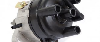
A contact distributor is no different in appearance from a contactless one.
Design of contact breaker-ignition distributor 30.3706
The contact distributor consists of the following elements:
- frame;
- rotor (shaft);
- slider (rotating contact);
- contact breaker;
- capacitor;
- centrifugal and vacuum ignition timing regulators;
- cover with main (central) and four side contacts.
The difference in the design of contact and non-contact distributors lies only in the device that generates the impulse
Housing and shaft
The base of the device is cast from aluminum. A cermet bushing is pressed into its upper part, playing the role of a support bearing for the distributor shaft. The side of the housing is equipped with an oiler through which the bushing is lubricated in order to reduce the friction force. The lower part of the shaft (shank) has splines for connecting additional engine elements to the drive gear. With their help it is set in motion.
The shaft of the device is driven by the drive gear of additional engine units
Runner
A slider is installed at the top of the rotor. It is made of plastic and has two contacts connected through a resistor. Their task is to receive voltage from the coil through the central electrode and transfer it to the side contacts of the distributor cap. The resistor is used to eliminate radio interference.
The slider has two contacts connected to each other through a resistor
chopper and capacitor
The breaker mechanism includes a group of contacts and a cam with four protrusions. The contacts are fixed on a movable plate, the rotation of which is ensured by a ball bearing. To be able to adjust the gap between the contacts, one of the mounting holes is made in the form of an oval. The moving contact is located on a spring-loaded lever. The other contact is stationary. In a calm position they are closed.
The cam is the thickened part of the shaft. Its protrusions serve to actuate the moving contact. When the breaker-distributor shaft begins to rotate, the cam with one of its protrusions rests against the movable contact block, moving it to the side. Then the protrusion passes the block and the contact returns to its place. This is the simple way to close and open the low voltage circuit in the contact ignition system.
The pulse is formed by opening the breaker contacts
Despite the fact that the voltage on the contacts is small, when they open, a spark is still formed. In order to eliminate this phenomenon, a capacitor is installed in the breaker circuit. It is attached with a screw to the distributor body.
The capacitor prevents the formation of a spark at the contacts during their opening
Centrifugal regulator
The primary adjustment of the moment of spark formation in VAZ 2107 cars is carried out by turning the entire distributor . Further adjustments are made automatically. The function of the centrifugal regulator is to change the ignition timing depending on the number of engine crankshaft revolutions.
The basis of the mechanism design is the support and drive plates. The first is soldered to a bushing that is movably fixed on the distributor shaft. It can rotate relative to the shaft with an amplitude of 15°. On top it has two axles on which weights are installed. The drive plate is mounted on the upper end of the shaft. The plates are connected to each other by two springs of different stiffness.
The centrifugal regulator adjusts the ignition angle depending on the crankshaft speed
When engine speed increases, centrifugal force also increases. It first overcomes the resistance of a softer spring, then a stiffer one. The weights rotate on their axes and rest against the support plate with their side protrusions, causing it to rotate together with the slider to the right, thus increasing the ignition timing.
Rotation of the support plate is ensured by centrifugal force
Vacuum regulator
The vacuum regulator is attached to the distributor body. Its role is to adjust the ignition angle depending on the load on the power plant. The design of the device consists of a reservoir, a membrane with a rod located in it, as well as a hose through which the regulator is connected to the primary chamber of the carburetor.
The vacuum regulator adjusts the ignition angle depending on the engine load
When a vacuum appears in the carburetor, it is transmitted through a hose to the reservoir of our device. A vacuum is created there. When this happens, the membrane moves the rod, and it acts on the rotating breaker plate, turning it counterclockwise, increasing the ignition timing.
The chopper plate rotates under the influence of vacuum created in the carburetor
Contact type distributor malfunctions and their symptoms
Taking into account the fact that the distributor is a rather complex device, it is subject to the influence of a number of negative factors that can damage the elements of its design. That is why the distributor can have a lot of malfunctions. Well, as for common device breakdowns, they include:
- electrical breakdown of the lid;
- wear of the central electrode or side contacts of the cover;
- burning of the slider contacts;
- electrical breakdown of the capacitor;
- violation of the gap between the contacts of the breaker;
- wear of the moving plate bearing.
If the contacts are severely worn, the cover must be replaced
Each of the listed malfunctions has its own symptoms, but in most cases they are of the same nature. If the distributor cover is punctured, its contacts or the slider contacts are worn out or burned, engine performance will deteriorate. The same thing will happen if the gap between the contacts of the breaker is broken, they become dirty or burnt. In this case, the following are most often observed:
- vibration;
- overheat;
- misfires;
- change in exhaust color;
- rare “lumbago” in the gas exhaust system;
- increase in gasoline consumption.
You can replace a faulty slider yourself
Failure of the moving plate bearing may be accompanied by a characteristic whistle or squeal coming from under the cover.
Selection of BSZ
When purchasing a new BSZ, you should pay attention to the presence of the components of the entire kit. The factory kit should contain:
- Distributor (main distributor). The code for engines 1.5 and 1.6 is 38.37061. For 1.3 engines, the number will be 38.3706–01, because the height of the 1.3 engine block is lower and the distributor shaft is shorter.
- Switch number 36.3734 or 3620.3734.
- High voltage coil (reel). Marking 27.3705
- Thin wires with connectors.
In appearance, the BSZ kit for the VAZ 2121 NIVA is very similar. But it’s better not to install this kit on a VAZ 2107 or a VAZ 2106, because the characteristics of the “six” and “seven” are very different from the “Niva”. Distributor brands for Niva: 3810.3706 or 38.3706–10.
The best manufacturer of electronic ignition systems for old VAZ cars is. The production capacity base is located in the city of Stary Oskol. According to reviews from car owners of classic BSZ SOATE models, this is an excellent option.
Wires for connecting electrical appliances
| Connection type | Section, mm 2 | Insulation color |
| Negative terminal of the battery - vehicle ground (body, engine) | 16 | Black |
| Starter positive terminal - battery | 16 | Red |
| Positive contact of the generator - plus battery | 6 | Black |
| Generator - black connector | 6 | Black |
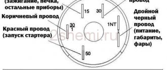
| Terminal on the generator “30” – white MB block | 4 | Pink |
| Starter connector “50” – starter relay | 4 | Red |
| Starter Start Relay - Black Connector | 4 | Brown |
| Ignition switch relay - black connector | 4 | Blue |
| Ignition switch output “50” – blue connector | 4 | Red |
| Ignition switch connector “30” – green connector | 4 | Pink |
| Right headlight plug - ground | 2,5 | Black |
| Left headlight plug - blue connector | 2,5 | Green, gray |
| Generator output “15” – yellow connector | 2,5 | Orange |
| Right headlight connector - ground | 2,5 | Black |
| Left headlight connector - white connector | 2,5 | Green |
| Radiator fan - ground | 2,5 | Black |
| Radiator Fan - Red Connector | 2,5 | Blue |
| Ignition switch output “30/1” – ignition switch relay | 2,5 | Brown |
| Ignition switch contact “15” – single-pin connector | 2,5 | Blue |
| Right headlight - black connector | 2,5 | Grey |
| Ignition switch connector “INT” – black connector | 2,5 | Black |
| Six-pin block of the steering column switch - “ground” | 2,5 | Black |
| Two-pin block of the steering column switch - glove box illumination lamp | 1,5 | Black |
| Glove compartment light - cigarette lighter | 1,5 | Black |
| Cigarette lighter - blue block connector | 1,5 | Blue, red |
| Rear window defroster - white connector | 1,5 | Grey |
Installation of contactless ignition for VAZ 2107, 2106
To install the BSZ with your own hands, you will need the following tools:
- Screwdrivers (flat and Phillips);
- Open-end wrenches 8, 10, 13 mm;
- Pliers (pliers);
- Candle key;
- Drill or screwdriver with a drill diameter of 3-3.5 mm. You will have to drill two holes in the body to secure the switch.
- A special wrench for rotating the crankshaft of an internal combustion engine or a regular open-end wrench of 30 mm.
An inspection hole for installing the ignition is not required. Here, in fact, is the procedure for removing the old contact ignition:
- Open the hood, disconnect the battery and disconnect the high-voltage wires from the spark plugs.
- Unscrew the spark plugs.
- Rotate the engine crankshaft until the piston in the first cylinder reaches top dead center (TDC). You can use a long screwdriver or wire to check where the piston is located. Make sure that the mark on the engine crankshaft pulley coincides with the very first long mark on the cylinder block.
- Disconnect the latches of the distributor cover and remove it with the wires. Draw a mark on the valve cover opposite the slider.
- Disconnect the hose coming from the carburetor and all distributor wires.
- Unscrew the fastening nut and remove the distributor along with the gasket.
- Unscrew the coil mounts (remember which wires are attached where) and remove it.
The procedure for installing contactless electronic ignition on a VAZ 2106-2107.
- Drill and attach the commutator next to the coil. But, do not place it under tanks with liquid.
- Remove the cover of the new distributor and put on the gasket.
- Install into the seat for the distributor so that the moving contact is opposite the drawn mark on the valve cover. Do not immediately tighten the nut all the way.
- Install the new coil where the old one was. The wires from the ignition switch relay, tachometer, and switch must be connected to the reel terminals. The wire from the electronic unit number 1 is connected to the coil terminal marked “K”, the wire from the 4th contact is connected to the coil terminal marked “B”.
- Check the gaps of the spark plugs (should be 0.8-0.9 mm) and screw them in place.
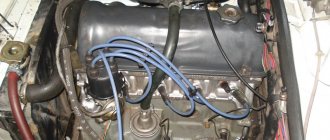
- Snap the distributor cover and connect the high-voltage wires (the central one from the coil and 4 wires to the spark plugs). We connect the wires to the spark plugs strictly in accordance with the designations.
- Connect the vacuum hose.
After installation in the correct sequence, we start the engine and begin setting up the ignition. If after installing a new electronic contactless ignition the engine does not start, you should check the correct connection of the coil wires and the high-voltage wires to the spark plugs. If the wires are normal, then the marks are not aligned.
Repair of contactless distributor
To determine and eliminate the malfunction, careful diagnostics are required, which involves dismantling and disassembling the device. The only element of the distributor that can be checked without disassembling it is the capacitor. Let's start with him.
Capacitor check
As already mentioned, the capacitor serves as a kind of spark arrestor. It prevents the formation of an electric arc between the breaker contacts at the moment they open. To check its functionality, you must perform the following steps:
- Disconnect the low voltage wire connecting the coil and distributor.
- Disconnect the capacitor wire from the distributor.
- Connect these two wires to a regular twelve-volt car lamp.
- Turn on the ignition. If the lamp lights up, the capacitor is broken.
- Replace the capacitor, check how the engine works.
Removing the distributor from the engine
The distributor is installed in the engine cylinder block on the left side. It is fixed on a special bracket with one nut. To dismantle the device you must:
- Disconnect the “-” wire from the battery terminal.
- Unfasten the two latches securing the breaker-distributor cover to the housing.
- Disconnect all armor wires from the cover.
Disassembling the distributor and replacing faulty elements
The functionality of each part of the device can be determined already at the stage of disassembling it. To do this you need:
- Carefully inspect the distributor cover from the outside and inside. Particular attention should be paid to the central electrode (carbon) and side contacts. If wear, damage, or severe burning is detected, the cover must be replaced.
Video: disassembling and repairing a contact distributor
Installation of the distributor and setting the ignition timing
The distributor is assembled after replacing the faulty parts in the reverse order. There is no need to install the cover to the device at this stage. To install the distributor and set the correct ignition timing, you should:
- Engage neutral gear.
- Install the distributor into its seat, not forgetting the O-ring.
Video: setting ignition timing
Setting the angle of the closed state of the contacts
The stability of the engine operation depends on how correctly the angle of the closed state of the contacts (the gap between the contacts) is inserted. To configure it you need:
- Using a “38” wrench placed on the crankshaft pulley mounting nut, rotate the shaft until the moving contact lever stops on one of the cam protrusions.
After carrying out this work, you can install the cover on the distributor body, connect the high-voltage wires and try to start the engine.
Installation of electronic ignition on video for classic VAZ 2101-2107 cars.
This video covers all the nuances.
How to adjust contactless ignition
Before setting the ignition on VAZ 2101-2107 cars, you need to warm up the engine a little, without letting it stall.
You can adjust either by ear or using a special device called a strobe for setting the ignition. A strobe is a device with which even a beginner can set the ignition correctly. For more information on setting up the ignition with a strobe, watch the video.
What is electronic or contactless ignition?
The electronic or contactless ignition system is a more advanced version of the SZ for cars. The block of such a device is assembled from electronic elements. Contactless ignition on a VAZ is called that way, because in this case the circuit is closed and opened thanks to an electronic switch. The latter, in turn, operates from a transistor, and not from a distributor contact, as was before.
The electronic ignition circuit on a VAZ has minor differences depending on the type of engine - injector or carburetor. In any case, this option is in practice more modern, as a result of which its popularity among our compatriots is growing. Due to differences in the connection diagram and some differences for the injector and carburetor, some car owners believe that the BSZ and the electronic system are different components, but this is not so.
BSZ scheme for the domestic “seven”
Why is it worth installing on “Seven”?
There are several reasons why you should install electronic ignition on a VAZ 2107.
Of course, it is important whether the engine is equipped with a carburetor or an injector, because the injection system does not have a distributor:
- If you install such an SZ, the car owner will no longer need to periodically service the contact group. That is, you can forget about oxidation and cleaning of contacts, as well as adjusting the gap.
- This VAZ 2107 ignition system is more reliable, since the contact group, which is most susceptible to breakdowns and wear, is simply absent.
- In this case, the spark will be distributed more evenly and stably throughout the engine cylinders, and this will not be affected by the performance of the power unit.
- The service life of the distributor as a whole increases as a result of the disappearance of vibration and shock of the axle in the case of the action of the so-called cams on the contacts.
- If the VAZ ignition timing is set and the system is configured correctly, and the engine operates in normal mode, there is a chance of saving gasoline. During normal operation of the internal combustion engine, its power can also be increased, especially since as a result of complete combustion of the mixture in the engine cylinders, there will be fewer harmful emissions.
- It will be easier to start the engine in cold weather, since the voltage level at the spark plugs will always be stable:
Additional designations
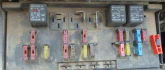
When connecting a generator or tampering with the wiring and ignition system of a VAZ, you should know the location of the fuse box in the car. There are 17 of them in total, of which 2 are reserve.
- reverse gear rear lamps;
- electric motors for headlight and glass washer pumps;
- heated rear window;
- direction indicators, hazard warning lights;
- fog lights;
- tachometer, voltmeter, warning lights on the dashboard;
- cigarette lighter and clock;
- sound signal;
- interior lighting, brake lamps;
- high beam headlights;
- high beam warning lamp;
- engine compartment lighting and license plate lighting;
- glove compartment lighting;
- low beam on the right;
- low beam on the left.
The electrical diagram of the VAZ 2022 car will help in repair and maintenance. You can download the image in high resolution using the link.
PROMOTION: SALE OF NEW CAR 2022 PRODUCTION
from 606,900 rub.
from 489,000 rub.
Author of the material: Dumchenkov Mikhail
Did you like the material? Share with your friends:
Have questions about car repairs? Ask them in the consultation section, to do this, click on the link below.
auto mechanic
- Audi
- Brilliance
- Faw
- Ford
- Chevrolet
- Citroen
- Geely
- Haval
- Changan
- Chery
- Datsun
- Great Wall
- Hyundai
- Kia
- Lada
- Volkswagen
- Renault
- Nissan
- Toyota
- Honda
- Mitsubishi
- Opel
- Lifan
- Mazda
- Skoda
- Rest
- Acura
- Alfa Romeo
- Audi
- Bentley
- BMW
- Cadillac
- Chery
- Chevrolet
- Citroen
- Daewoo
- Dodge
- Fiat
- Ford
- GAZ
- Geely
- Hawtai
- Honda
- Hyundai
- Infiniti
- Jaguar
- Jeep
- KIA
- Land Rover
- Lexus
- Lifan
- Lincoln
- Mazda
- Mercedes-Benz
- Mini
- Mitsubishi
- Nissan
- Opel
- Peugeot
- Porsche
- Renault
- Skoda
- SsangYong
- Subaru
- Suzuki
- Toyota
- UAZ
- VAZ
- Volkswagen
- Volvo
- New cars 2019
- New cars 2018
- Test drives
- Jeeps
- Repair and service
- Engine
- Chassis
- Electrical equipment
- Signaling
- Cigarette lighter
- Car Reviews
- Photo and video galleries
- News
- Tires
© 2022 Daciaclubmd.ru. If you do not agree with any provision of this Disclaimer, do not use this Site. Please read Disclaimer and Privacy Policy before use.
Installation Guide
How to install BSZ with your own hands on the “seven”? How to properly set and adjust the device? First you need to prepare everything you might need.
Tools and materials
To complete this task you will need:
- a set of keys;
- self-tapping screws;
- screwdriver set;
- construction drill.
Stages
Installation of electronic ignition must be carried out on a de-energized on-board network, otherwise a short circuit may occur in the system.
So disconnect the battery and then follow these steps:
- Disconnect all high-voltage wires from the spark plugs.
- Dismantle the distributor cover.
- After this, by rotating the crankshaft, it is necessary to set the slider to a position perpendicular to the axis of the power unit. Also mark the location on the middle mark of the distribution element scale, this will allow you to make adjustments without any problems in the future.
- The distributor fixing nut must be unscrewed, after which the device is dismantled.
- A non-contact regulator is installed instead of the dismantled distributor, while the slider and housing must be placed in the desired position in accordance with the previously established marks.
- The device cover is installed.
- Then you need to connect the high-voltage cables with the spark plugs.
- After completing these steps, you can replace the coil. In general, this task is quite simple, but when performing it, you should take into account the position of contacts B and K. If they are different on the new short circuit, then the element should be rotated relative to the fastener so that the contacts are located similar to the one that was installed previously.
- At the final stage of installation, the switch is installed; the best option would be to place it between the washer expansion tank and the headlight. The mechanism is fixed using self-tapping screws, and the so-called zero wiring should be brought out under one of them. As for the radiator, it should be leaned against the body.
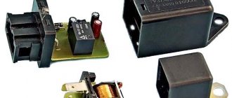
Switch
The last element in the circuit, the presence of which is required by a contactless electronic ignition system, is a switch. The ideal place in which it can be installed in a VAZ 2107 is between the washer reservoir and the left headlight. There is a flat area on which we will install the switch, with the radiator facing the body. Having leaned the switch, we mark the places for drilling holes in the body, through which we fasten it with self-tapping screws; in this case, you need to screw the black (neutral) wire from the connection block under one of the screws.
After completing all the work described above, you should once again carefully check the connection of the wires according to the circuit diagram. If everything is done correctly, you can try to start the engine. Usually there are no problems with this; all that remains is to adjust the ignition to ensure the most efficient operation of the engine.
Adjustment features
As for how to set the installed ignition unit on the “seven”, then, of course, this procedure is best carried out using special equipment. But since such installations can only be found in car repair shops, the adjustment procedure can be done by ear. Before you begin the process, you need to make sure that both the carburetor and the pump are operating normally. The process itself is performed as follows:
- First the engine warms up.
- Then the distributor fixing nut is unscrewed.
- The distributor itself should be slowly turned in different directions, while the motor should be running. The mechanism is turned until the operation of the internal combustion engine is smooth and the speed increases.
- After this, the fixing nut needs to be tightened.
- As for checking, to do this, you need to accelerate the car at third speed to about 50 km/h, then engage fourth gear and press the gas pedal. In this case, the sound of “fingers” or detonation should be heard from under the hood, which will last until the car’s speed increases by 5 km/h. If the sound continues longer, the distributor should be released and turned clockwise by about one degree. If you are unable to adjust the ignition yourself in this way, it is better to seek help from specialists - this procedure is inexpensive, but you will be sure that the engine will work normally.
Sorry, there are no surveys available at this time.
Examination
The easiest way to test a switch is to try replacing it with a known good one. But this can only be done if a working switch is at hand. It is not advisable to buy a new unit just to test the operation of the old one. There is a cheaper and not particularly complicated way. To test the switch, you only need a standard set of keys and a test lamp. This is enough to verify the presence or absence of pulses supplied to the ignition coil. Before checking the switch, make sure that “plus” is supplied to it and the ignition coil. Also check the connection contacts of the Hall sensor and the functionality of the sensor itself. Checking the VAZ 2107 ignition switch is performed as follows:
- turn off the ignition;
- unscrew the nut on the ignition coil and disconnect the brown wire marked “K” (the wire goes to connector “1” on the switch);
- connect a test lamp to the gap between the wire terminal and the coil terminal;
- turn on the ignition;
- turn the key and start the starter.
A flashing light indicates a working switch. If the lamp does not light, the switch needs to be replaced.
Replacing a VAZ 2107 switch
To replace the switch, you must complete the following steps:
- turn off the ignition;
- disconnect the wire block from the switch connector;
- unscrew the fastening nuts;
- remove the old switch and put a new one in its place;
- tighten the fastening nuts;
- connect the wire block to the connector.