Along with other options for improving the units and systems of the VAZ 2107, a non-contact (electronic) ignition system (BSI) is being considered instead of the standard one. This modernization makes it possible to provide stable increased voltage on the spark plugs, which, in turn, makes it easier to start the engine and increases spark energy.
Installing and adjusting a contactless ignition system is quite a difficult task, so if you do not have sufficient skills in working with automotive electronics, it is better to entrust this work to specialists. If you feel that you are able to install the BSZ kit on a VAZ 2107 yourself, then carefully study these instructions and get to work.
To work you will need the following set of tools and materials:
- Key to 8;
- Key for 10;
- Key to 13;
- Phillips screwdriver;
- Two self-tapping screws;
- Drill with a drill of the same diameter as the self-tapping screws;
Naturally, in addition to all this, an electronic non-contact ignition system must be purchased, or rather a set of its components: a coil, a switch, a distributor and wires for connecting all the elements together.
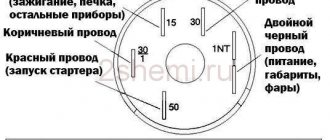
Below is a schematic diagram according to which the contactless ignition system for the VAZ 2107 is connected.
Prerequisites for failure
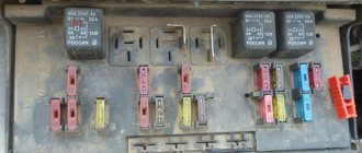
Please note that the engine control system malfunction warning lamp, located on the device panel in the signaling unit, is the first indicator of deviations in the operation of the VAZ 2107, where an injector is used.
Some modifications of the VAZ 2107 provide for the location of the warning lamp on the upper insert of the radio panel. By starting the ignition, a system malfunction is tested, which means the lamp lights up and goes out after the engine starts. A prerequisite for diagnosing the ignition system is that the lamp does not go out when the engine is running.
By starting the ignition, a system malfunction is tested, which means the lamp lights up and goes out after the engine starts. A prerequisite for diagnosing the ignition system is that the lamp does not go out while the engine is running.
In situations where there is a malfunction, VAZ 2107 owners replace the spark plugs. Old factory spark plugs are usually replaced with iridium spark plugs from NGK or Denzo. Do not forget that only those spark plugs that are designed for the appropriate type of injection are suitable here.
The type of ignition system is no less important in determining the parameters of the spark plug. Often such manipulation does not provide much improvement (plugs have a fairly long service life), so the non-contact ignition system undergoes a full diagnosis.
Do you want to know more about how to install
valve timing according to marks on VAZ 2101-
VAZ 2107
? And so.
Examination
The easiest way to test a switch is to try replacing it with a known good one. But this can only be done if a working switch is at hand. It is not advisable to buy a new unit just to test the operation of the old one. There is a cheaper and not particularly complicated way. To test the switch, you only need a standard set of keys and a test lamp. This is enough to verify the presence or absence of pulses supplied to the ignition coil. Before checking the switch, make sure that “plus” is supplied to it and the ignition coil. Also check the connection contacts of the Hall sensor and the functionality of the sensor itself. Checking the VAZ 2107 ignition switch is performed as follows:
- turn off the ignition;
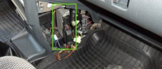
- unscrew the nut on the ignition coil and disconnect the brown wire marked “K” (the wire goes to connector “1” on the switch);
- connect a test lamp to the gap between the wire terminal and the coil terminal;
- turn on the ignition;
- turn the key and start the starter.
A flashing light indicates a working switch. If the lamp does not light, the switch needs to be replaced.
Replacing a VAZ 2107 switch
To replace the switch, you must complete the following steps:
- turn off the ignition;
- disconnect the wire block from the switch connector;
- unscrew the fastening nuts;
- remove the old switch and put a new one in its place;
- tighten the fastening nuts;
- connect the wire block to the connector.
Adjusting the ignition timing
Ignition timing is the moment a spark occurs at the spark plug electrodes. It is determined by the angle of rotation of the crankshaft journal relative to the top dead center (TDC) of the piston. The ignition angle has a noticeable effect on engine performance. If its value is too high, ignition of the fuel in the combustion chamber will begin much earlier than the piston reaches TDC (pre-ignition), which can lead to detonation of the fuel-air mixture. If sparking is delayed, this will lead to a decrease in power, engine overheating and increased fuel consumption (delayed ignition).
The ignition timing on the VAZ 2106 is usually set using a car strobe light. If there is no such device, you can use a test lamp.
Setting the ignition timing using a strobe light
To adjust the ignition timing you will need:
- car strobe light;
- key to 13;
- a piece of chalk or a correction pencil for printed text.
The installation process itself is carried out in the following order:
- We start the car engine and warm it up to operating temperature.
- Disconnect the hose from the vacuum corrector located on the distributor body.
- We find three marks (low tide) on the right engine cover. We are looking for the middle mark. To make it better visible in the strobe beam, mark it with chalk or a correction pencil.
Video: adjusting the ignition using a strobe light
Setting the ignition timing using a warning light
To adjust the ignition using a lamp you will need:
- the warning lamp itself;
- 36 head with handle;
- key to 13;
- 16mm spark plug wrench with wrench.
The work order is as follows:
- Using a 36mm socket, placed on the crankshaft pulley ratchet, we rotate the shaft until the mark on the pulley aligns with the casting on the cover. When using gasoline with an octane rating of 92 and higher, the mark on the pulley should be aligned with the middle ebb. If the octane number is less than 92, the mark is placed opposite the last (long) ebb.
- We check whether the distributor is installed correctly in this position. Unfasten the latches and remove the distributor cover. The outer contact of the distributor slider should be directed towards the spark plug of the first cylinder.
Video: adjusting the ignition using a light bulb
Installing the ignition by ear
If the valve timing is set correctly, you can try to set the ignition by ear. This is done as follows.
- Warm up the engine.
- We drive out onto a flat section of the highway and accelerate to 50–60 km/h.
- We switch to fourth gear.
- We sharply press the accelerator pedal all the way and listen.
- With the ignition set correctly, when the pedal is pressed, a short-term (up to 3 s) detonation should occur, accompanied by the ringing of the piston pins.
If detonation lasts more than three seconds, ignition is early. In this case, the distributor body is rotated several degrees counterclockwise, and the verification procedure is repeated. If there is no detonation at all, the ignition is late, and the distributor body must be turned clockwise before repeating the test.
Symptoms of a problem
Of course, repair of the distributor is carried out only after it has been diagnosed.
Listed below are the main symptoms of a distributor malfunction, in which it is necessary to disassemble and check the mechanism:
- the car began to jerk while driving;
- the engine basically won’t start;
- when the speed increases, detonation may be heard (knock of “fingers”);
- it takes longer to increase speed;
- Gasoline consumption has increased.
Of course, these symptoms may indicate other problems. Therefore, before repairing a disassembled unit, you need to know how to set, how to adjust and how to check the distributor.
To check it, you need to disassemble it and pay attention to the condition of the following components:
- slider;
- oxidized or burnt distributor cover contacts;
- failure of the Hall sensor (its bearing element could fail or become jammed);
- distributor capacitor;
- presence of cracks on the device body;
- stuffing box;
- Repair of the ignition distributor should also be carried out if engine fluid gets into its structure.
Distributor for car
Setting the ignition timing with advance
This setup is completely easy to do. Even a beginner can cope with this task. To do this, prepare a 13 mm wrench and a special 38 mm crankshaft wrench in advance.
If your car is started, be sure to turn off the engine, since you can only turn on the ignition when the engine is turned off. First, the piston of the first cylinder is installed at the top dead center of the compression stroke, that is, in the ignition position. Before doing this, remove the candles and plug the hole from them with cotton.
You need to align the mark on the crankshaft and the front engine cover. To do this, use a wrench to start turning the crankshaft clockwise. During this action, the air compressed there should push out the cotton wool, thereby indicating the compression stroke. Continue turning the shaft slowly until the marks on the timing belt pulley and cover line up.
Please note that there are 3 marks on the cover:
- The first indicates ignition advance by 10º;
- the second – by 5 º;
- the third is equal to zero.
Since a VAZ 2107 engine with a carburetor runs on 92 or 95 gasoline, we need to set the ignition for these types of fuel. That is why you should select the second mark, which will indicate an ignition advance of 5º.
Once the required parameters match, put the spark plugs in place and remove the wires. The system is ready for use.
Installing an electronic BSZ instead of a contact one
Today it is very rare to find a “seven” with contact ignition. With the arrival on sale of switches, distributors and coils for electronic spark generation systems, owners of classics began to massively re-equip their cars.
DETAILS: Replacing the air filter on a Hyundai Solaris with your own hands
What is included in the BSZ kit
In addition, you will need spark plugs (preferably new ones) with a gap of 0.7–0.8 mm and a set of high voltage wires. Coil type B-117A (used in a contactless system) is not suitable for electronic ignition. Its characteristics do not correspond to those of other equipment in the circuit.
Preparation
Before installing a new VAZ-2107 distributor for a contact ignition system, you need to adjust the gap between the contacts of the breaker. It is more convenient to do this with the device removed from the car. We check the gap with a flat feeler gauge. The value is set from 0.35 to 0.45 mm.
In this case, the protrusion of the cam should move the moving contact away from the stationary contact as much as possible. We adjust by slightly loosening the screws, and then tighten them more firmly and check the gap again. Contacts that have worked hard may have a protrusion on one and a depression on the other, which interferes with adjustment.
Before removing the old distributor, mark its position relative to the cylinder block with a marker. You also need to accurately mark the position of the moving contact (slider) relative to the body. If all this is not done, the settings will be violated and the engine will not start.
Installation
Having established exactly the same position of the roller in the body on the new distributor, carefully insert it into the hole in the block, slightly turning the roller to align the splines. Having “planted” the device in place by rotating the body relative to the block, we set the approximate advance angle, as on the old distributor.
Secure with a washer and nut, but not too tight. Now you need to plug in the high voltage wires. This is easy to do - each contact on the distributor cover has the number of the cylinder to which it needs to be connected. We connect the wire from the ignition coil to the central terminal.
The wires should fit tightly, with a slight tension, the protective caps should be pushed all the way down. Don’t get carried away, don’t bend the petals of the wire tips too much, otherwise later, when you try to remove them, you’ll tear off the wires “with their roots”! A wire goes from the contact wire to the “K” terminal of the ignition coil, usually it is green.
If your VAZ-2107 is equipped with a contactless ignition system, then you need to connect a connector with three wires. Having plugged it into the socket, check the fit of the wires; it happens that they “crawl out” of their places and the device does not work. Everything is done, the new distributor is installed and ready for use.
Instructions for setting up the ignition
The cause of engine overheating and loss of power may be late ignition. This may manifest itself as popping noises in the intake manifold. Therefore, you need to know how to install the ignition correctly (the author of the video is Nail Poroshin).
Installation is carried out according to the marks as follows:
- First, you need to set the piston on the first cylinder to TDC and align the installation indicator mark with the mark on the crankshaft pulley.
- Next, the crankshaft must be turned counterclockwise until the marks 9 on the pointer coincide with the marks on its pulley.
- Then you need to loosen the bolt on the top plate of the corrector, thanks to which it is attached to the breaker.
- Next, you need to connect one control wire to the car body (ground) and the second to the breaker terminal. After turning on the ignition, the breaker should be turned slowly until the control lights up. This indicates that the contacts have begun to open.
- Now you need to tighten the breaker mounting bolt and install the cover and rotor. In the area opposite to the one where the rotor plate was installed, you need to connect the high-voltage wire to the spark plug on the 1st cylinder. The remaining wires are connected to the cylinder spark plugs, according to the order in which they work: 1-5-4-2-6-3-7-8.
It is necessary to set the ignition timing of the GAZ-53 accurately, since with deviations the engine power decreases and fuel consumption increases. In addition, burnout of valves, pistons, breakdowns in the cylinder head gasket and other problems associated with detonation are possible.
Therefore, the final adjustment is performed with the engine running, which warms up to a coolant temperature in the range of 80 - 90 degrees. With the engine running at idle speed, you need to loosen the fasteners of the distributor with a 10mm wrench so that it can be turned. After slightly turning the distributor counterclockwise, tighten the fastening bolt.
Pressing on the gas is how the power unit works. If you hear a “ringing of fingers,” that is, detonation occurs, turn the distributor clockwise in the opposite direction. Through trial and error we set the desired advance angle.
The test is done on a moving vehicle. With stable operation of the power unit, tuning is no longer needed.
Sometimes the distributor is pushed to the extreme position, but the adjustment is not enough. In this case, you need to check the position of the distributor drive relative to the engine.
A check is performed with the engine not running:
- First, marks are placed on the front crankshaft pulley. They must match on the 1st and 6th cylinders. To avoid making a mistake, it is better to remove the valve covers from the first 4 cylinders and check the valves. If the valve marks are in the correct position, the valves in the 1st cylinder will be free.
- Having removed the distributor, we inspect how the drive is installed. If it is located parallel to the motor, then it needs to be replaced or repaired; adjustment, in this case, will not help.
- If the position of the drive is incorrect, you need to unscrew the fastening nut and remove the part.
- After the drive is completely installed in its place, you need to check that the groove for the distributor runs parallel to the internal combustion engine (in the direction of travel of the car), and a small section of the bushing on the distributor faces the 4th and 8th cylinders (towards the driver) . By experience, you need to achieve the correct position of the distributor drive.
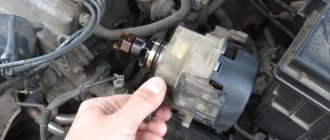
Coil
Next, you need to replace the ignition coil. Using a size 8 wrench, unscrew the nuts securing the wires to the coil contacts. Using a 10mm wrench, unscrew the mount of the coil to the body. Installing a new coil requires special attention - you should take into account the possible discrepancy between the locations of contacts “B” and “K”. For convenience, you can rotate the new electronic coil relative to the fastener, thereby placing the contacts in the same way as on the old one.
Having secured the coil, we connect old wires to its contacts (usually one blue, the other brown), and new ones, with connectors for connecting to the distributor and switch. They usually have the same colors as the standard ones. Typically, in a VAZ 2107, brown wires are connected to contact “K”, and blue wires are connected to “B”. It remains to connect the high-voltage wire that connects the coil and the distributor.
Ignition systems for VAZ-2101-2107 cars
Contact ignition system
The contact ignition system consists of an ignition switch, an ignition coil, a distributor-breaker, spark plugs, low and high voltage wires.
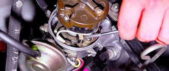
Ignition distributor 30.3706
The ignition distributor converts low-voltage direct current into pulsed current and distributes high-voltage current pulses across the spark plugs. It is structurally combined with a chopper and centrifugal and vacuum ignition timing regulators.
| rice. 1 |
The distributor is installed in the front of the cylinder block on the left side.
The distributor housing is cast from aluminum alloy. Two plain bearings are pressed into the housing shank, in which the roller rotates. A breaker cam is made on the top of the roller, and a centrifugal ignition timing regulator and rotor (runner) are also mounted. When the roller rotates, the weights of the centrifugal regulator diverge under the action of centrifugal forces and rotate the tetrahedral cam of the breaker at a certain angle in the direction of rotation of the roller. In this case, the contacts open with some advance, the greater the higher the engine speed. The rotation angle is limited by the size of the groove in the rotor support plate.
| rice. 2 |
The breaker consists of a stand with a fixed contact and a movable contact with a textolite stop, which is pressed by a flat spring to the tetrahedral cam of the distributor roller. When the cam rotates, the contacts close and open. The cam is lubricated with a felt fold soaked in engine oil.
When operating a car, it is necessary to systematically check and adjust the gap between the breaker contacts.
The plate on which the breaker mechanism is mounted is mounted on a ball bearing, allowing it to rotate around the axis of the roller.
The plate is connected by a rod to the diaphragm of the vacuum ignition timing regulator. The vacuum (supplied through the hose from the rear throttle space of the carburetor) acts on the diaphragm of the vacuum regulator, and the rod rotates the breaker mechanism together with the movable plate relative to the tetrahedral cam, thereby ensuring optimal ignition timing depending on the engine load.
To reduce sparking between the contacts of the breaker, a capacitor is connected in parallel with them. It is fixed externally to the distributor housing.
The top of the distributor housing is closed with a cover with sockets for high voltage wires. A spring-loaded carbon is mounted inside the lid into its central electrode. A rotor with a contact plate (runner) distributes high voltage current to the spark plugs in accordance with the firing order of the cylinders (1 - 3 - 4 - 2). The ignition distributor shaft rotates clockwise (when viewed from above).
When adjusting the ignition timing, turning the distributor housing clockwise reduces the timing, counterclockwise increases it.
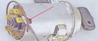
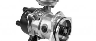
Ignition coil B-117A
The ignition coil is a step-up transformer that converts low voltage pulse current (12V) into high voltage current. The coil windings are installed in a housing made of thin galvanized steel. The housing cover is made of insulating material, has two low-voltage terminals and a socket for a high-voltage wire. The coil body is filled with transformer oil, which cools the windings.
The ignition coil is installed in the engine compartment and secured to the left mudguard of the body with two nuts.
Ignition switch
The ignition switch is a combined switch, consisting of a lock with an anti-theft device and a contact part, assembled in one housing. The switch is installed on the left side of the steering column in a special bracket and secured with two screws.
Spark plug
The spark plug ignites the working mixture in the cylinder with a spark discharge. The design of the candle is non-separable.
For a properly functioning spark plug, the color of the central electrode insulator skirt should be gray or light brown.
| rice. 3 |
The car uses spark plugs A17DVR (A17DVRM) or their analogues.
The main components of the distributor and a description of its operation
Device.
The distributor is assembled in a housing. Inside it, a contact group is mounted on a bearing: moving and fixed contacts or a Hall sensor (for contactless ignition). To correct the advance angle, the vacuum regulator can rotate the contact group at a small angle relative to the housing.
A capacitor is secured to the bottom of the housing with screws. A drive roller is installed on bushings in the center of the housing. Its bottom has splines with which it engages with the drive gear. In the upper part of the roller there are contact drive cams (for contact ignition) or a steel cup with four slots - a screen (for contactless ignition).
At the very top, on a steel platform, two weights and two springs of the centrifugal ignition regulator are installed. A plastic housing with a moving contact and noise suppression resistance of the high voltage distributor (slider) is screwed onto the top with two screws.
The entire structure is closed with a lid on two spring latches. The body and cover have a tongue and groove so that they fit together in only one position. The cover contains contact terminals for high voltage wires from the spark plugs and from the ignition coil.
Job.
The distributor is connected through the drive to the engine crankshaft and rotates with it. For two full revolutions of the crankshaft, the distributor shaft makes one revolution. This is due to the fact that our engine is four-stroke. When installing the distributor in place, the roller is oriented in strict accordance with the operating order of the engine.
This is done so that the contacts open and the spark jumps on the spark plug when the piston of each cylinder, compressing the combustible mixture, does not reach top dead center (TDC) by a few millimeters. This is called ignition advance. When the number of revolutions increases, the distance must be increased, and when it decreases, it must be decreased, which is what the centrifugal regulator does.
Its weights, under the influence of centrifugal force, which is greater the higher the engine speed, diverge to the sides and move the cams relative to the roller, making ignition “earlier.” When the engine speed decreases, the springs return the weights to their place and the ignition becomes “later”.
This is necessary to increase engine power and efficiency. In addition to the centrifugal one, a vacuum ignition timing regulator is also installed on the distributor. Its function is to fire “earlier” at low throttle opening angles and “later” at sharp throttle opening angles.
Diagnostics of malfunctions of the ignition module of injection VAZ 2107
The ignition of the injection VAZ 2107 is completely electronic and is considered quite reliable. However, problems can arise with it too. The module plays an important role in this.
Signs of a malfunctioning ignition module
Symptoms of a faulty module include:
- the Check engine warning light on the dashboard lights up;
- floating idle speed;
- engine tripping;
- dips and jerks during acceleration;
- change in sound and color of exhaust;
- increased fuel consumption.
However, these signs can also appear in case of other malfunctions - for example, in case of problems with the fuel system, as well as in case of failure of some sensors (oxygen, mass air flow, detonation, crankshaft position, etc.). If the engine starts to operate incorrectly, the electronic controller puts it into emergency mode, using all available resources. Therefore, when the engine operation changes, fuel consumption increases.
In such cases, you should first of all pay attention to the controller, read information from it and decipher the error code that has occurred. To do this, you will need a special electronic tester, available at almost any service station.
If the ignition module fails, error codes in engine operation may be as follows:
- P 3000 - no sparking in the cylinders (for each cylinder the code may look like P 3001, P 3002, P 3003, P 3004);
- P 0351 - break in the winding or windings of the coil responsible for cylinders 1–4;
- P 0352 - a break in the winding or windings of the coil responsible for 2–3 cylinders.
At the same time, the controller can produce similar errors in the event of a malfunction (break, breakdown) of high-voltage wires and spark plugs. Therefore, before diagnosing the module, you should check the high voltage wires and spark plugs.
Main malfunctions of the ignition module
The main malfunctions of the VAZ 2107 ignition module include:
- a break or short to ground in the wiring coming from the controller;
- lack of contact in the connector;
- short circuit of the device windings to ground;
- break in the module windings.
Checking the ignition module
To diagnose the VAZ 2107 injection module, you will need a multimeter. The verification algorithm is as follows:
- Raise the hood, remove the air filter, find the module.
- We disconnect the block of the wiring harness coming from the controller from the module.
- We set the multimeter to measure voltage in the range 0–20 V.
- Without starting the engine, turn on the ignition.
- We connect the negative (usually black) probe of the multimeter to ground, and the positive one to the middle contact on the harness block. The device must display the voltage of the on-board network (at least 12 V). If there is no voltage or it is less than 12 V, the wiring or the controller itself is faulty.
- If the multimeter shows a voltage of at least 12 V, turn off the ignition.
- Without connecting the connector with wires, disconnect the high-voltage conductors from the ignition module.
- Switch the multimeter to resistance measurement mode with a measurement limit of 20 kOhm.
- To check the device for an open circuit in its primary windings, we measure the resistance between contacts 1a and 1b (the outermost ones in the connector). If the resistance of the device tends to infinity, there is indeed an open circuit in the circuit.
- We check the module for breaks in the secondary windings. To do this, we measure the resistance between the high-voltage terminals of the first and fourth cylinders, then between the terminals of the second and third cylinders. In operating condition, the module resistance should be about 5–6 KOhm. If it tends to infinity, the circuit is broken and the module is faulty.
How to check the distributor
The most common manifestations of an ignition malfunction will be as follows:
- floating idle;
- engine that won't start;
- engine stalling while driving.
Most often, the cause of this may be the distributor. The easiest way to check the performance of the ignition, including the distributor, is as follows. To do this, unscrew the spark plug, bring it to the engine and start it, observing the appearance of a spark. If it is not there, then you need to check the functionality of the high voltage wires. If there is no spark again, then the diagnosis is clear - the distributor has failed.
In this case, you need to visually check the condition of the slider, the condition of the contacts and the distributor cover. Burnt contacts are cleaned and dust and debris are removed from the internal surfaces of the distributor. In a workshop or garage, you can check the performance of the ignition and distributor using measuring instruments and indicators.
The distributor appeared on the car almost simultaneously with the gasoline engine, and for many years remained almost unchanged, including on domestic cars of the 2109, 2106, 2107, 2108 family. And only after the advent of a modern element base, which includes the Hall sensor, gave way to contactless and then microprocessor ignition systems. » alt=»»>
Ignition malfunctions of the VAZ 2107, regardless of the type of system itself (contact or non-contact), are often associated with a distribution switch (distributor). Despite its complex electromechanical design, almost any breakdown can be fixed with your own hands.
About the ignition system in detail
The ignition system of a gasoline internal combustion engine “breathes” due to spark formation on the SZ elements, which ignite the mixture in the combustion chamber. Obviously, the efficiency of the fuel combustion process, the functioning of the engine as a whole, etc. directly depend on the timing of ignition. For this reason, the ignition must be set to the most optimal position for normal operation.
Most modern cars are equipped with electronic ignitions that do not require any adjustments. However, for the normal functioning of cars with a carburetor ignition system equipped with a 4-stroke internal combustion engine, adjustment is required. It is thanks to this that timely sparking is guaranteed.
Correct adjustment of the distributor
The first sign that something wrong is going on with the ignition system is characteristic knocks and noises while the car is driving.
A 4-stroke internal combustion engine operates according to the following scheme:
- First, fuel is injected.
- Then the compression stroke occurs.
- A working stroke is in progress, during which a spark is generated that ignites the mixture.
- Finally, the last step is the release of the working.
Ignition, to be more precise, occurs not during the working moment, but at the border of the compression stroke and the working stroke. At this very moment, the SZ produces a spark that ignites the fuel mixture.
Important point. The SZ is required to produce a spark at the moment when the motor piston almost reaches a position called TDC.
Setting the ignition on the distributor
It happens that the moment of operation of the SZ becomes a little off as time passes, which entails a decrease in the time of effective spark action. The time interval between reaching TDC and ignition of the fuel is called ignition timing. Its value is determined by a numbered scale marked on the crankshaft flywheel.
Distributor VAZ 2108-09
The PR on front-wheel drive VAZ cars with a carburetor engine is of the contactless type; it is fundamentally designed in the same way as the contactless distributor on the Classic, but has its own design features and looks completely different in appearance. The shaft of the VAZ-2108 distributor is short, it is driven directly from the camshaft, and is installed on the cylinder head.
Switch
The commutator is necessary to create an electrical impulse by interrupting the constant supply of current from the battery to the primary winding of the coil. The BSZ VAZ 2107 uses a switching device of type 3620.3734. The working elements in it are ordinary bipolar transistors, which open the circuit when a signal is received from the Hall sensor.
Switch 3620.3734 is built according to a simple single-wire circuit, in which the device body is connected to the vehicle ground and, accordingly, to the negative terminal of the battery. The advantages of using this unit instead of a traditional breaker include:
- no need for maintenance or adjustment;
- high spark energy, which makes it easier to start the engine in the cold season, as well as the ability to use gasoline with a lower octane number;
- the presence of a stabilization system that protects the Hall sensor from voltage surges.
Octane corrector
It's no secret that the gasoline we buy at gas stations often does not meet the standards provided by the car manufacturer for normal engine operation. As a result of using such fuel, clogging of the fuel system, an increase in the amount of deposits on piston parts, and a decrease in engine performance may occur. But the most dangerous thing for the power unit is detonation, which occurs due to the use of low-octane gasoline.
In cars with an electronic control system, detonation is eliminated using a special sensor and control unit. Such elements are found in injection “sevens”. The computer receives the signal from the sensor, processes it and automatically adjusts the ignition timing, increasing or decreasing it. The carburetor VAZ 2107 does not have such equipment. Drivers have to do this manually, turning the distributor in the manner described above.
But there is a special electronic device that makes it possible not to adjust the ignition angle after each refueling. It's called an octane corrector. The device consists of two parts: an electronic unit, which is installed in the engine compartment, and a control panel located in the car interior.
Noticing that the piston fingers begin to “ring”, the driver turns the knob on the control panel of the device, making the ignition later or earlier. Such a device costs approximately 200–400 rubles.
The “seven” distributor is indeed a complex device, but if you understand the design and operating principle, you can easily maintain, repair and adjust it yourself.
Ignition marks VAZ 2107
When adjusting the advance angle, you must focus on the marks marked on the crankshaft pulley and on the front engine cover.
There is a notch on the engine pulley that should align with one of three marks on the cover, depending on the fuel used.
The marks on the lid are of different lengths - short, medium and long. The first corresponds to an advance angle of 10 degrees, the second - 5 degrees, the third - 0 degrees (the mixture is ignited at TDC).
High octane fuel burns faster than low octane fuel. The VAZ 2107 is designed for gasoline with an octane number of 92-95, so the optimal advance for it is 5 degrees.
Ignition distributor-distributor "seven"
The distributor is used to generate pulse voltage in the low-voltage circuit of the ignition system, as well as distribute high-voltage pulses among the spark plugs. In addition, its functions include automatic adjustment of the spark advance angle.
What kind of distributors are there?
In the VAZ 2107, depending on the type of ignition system, two types of distributors can be used: contact and non-contact. In appearance they are practically no different. The difference between them lies in the device responsible for generating a pulse in the low-voltage circuit of the system. For the former, a group of contacts is responsible for this function, for the latter - an electromagnetic sensor, the operation of which is based on the Hall effect. In all other respects, the operating principle of the devices is identical.
Prerequisites for failure
Please note that the engine control system malfunction warning lamp, located on the device panel in the signaling unit, is the first indicator of deviations in the operation of the VAZ 2107, where an injector is used. Some modifications of the VAZ 2107 provide for the location of the warning lamp on the upper insert of the radio panel. By starting the ignition, a system malfunction is tested, which means the lamp lights up and goes out after the engine starts.
A prerequisite for diagnosing the ignition system is that the lamp does not go out when the engine is running.
By starting the ignition, a system malfunction is tested, which means the lamp lights up and goes out after the engine starts. A prerequisite for diagnosing the ignition system is that the lamp does not go out while the engine is running.
In situations where there is a malfunction, VAZ 2107 owners replace the spark plugs. Old factory spark plugs are usually replaced with iridium spark plugs from NGK or Denzo. Do not forget that only those spark plugs that are designed for the appropriate type of injection are suitable here.
The type of ignition system is no less important in determining the parameters of the spark plug. Often such manipulation does not provide much improvement (plugs have a fairly long service life), so the non-contact ignition system undergoes a full diagnosis.
Do you want to know more about how to install
valve timing according to marks on VAZ 2101- VAZ 2107
? And so.
Diagnostics of the distributor runner
The slider is replaced if this element can no longer perform its functions. You may need a multimeter for diagnosis.
How to check the slider at home, several options:
- The multimeter probes must be installed in the place where the slider itself is connected to the coal at the point of breakdown. To identify a breakdown, you need to carefully look at the device - the spark will go either completely to the side, or only partially. But it should be borne in mind that a breakdown cannot always be determined.
- Another diagnostic option is to test the device using a central cable type. You will only need to dismantle the cover itself, then bring the high-voltage cable from the reel to the distributor, then try to start the engine. When cranking the starter, if the distributor is broken, the spark will start to jump. If there is no slippage, then you don’t need to look for the cause of the problem here.
- If there is a crack on the runner, the spark will go to the side. In the event that the resistance of the element is completely burned out, but an attempt to restore the conductor could occur. In turn, this could lead to electrical breakdown of the element and its complete failure. In this case, it must be completely replaced.
After the repair, the distributor is adjusted. The adjusted mechanism is put in place; during installation, it is important to correctly match the marks and connect the high-voltage cables. The procedure for adjusting the ignition as a whole may differ depending on the vehicle, and there may be several adjustment options.
General tips for connecting high-voltage wires.
Checking high-voltage wires. To check the wires, you will need a multimeter tester. Check the resistance of the wires - it should be no more than 20 KOhms (in practice, the longest wire of cylinder 1 has a resistance of up to 10 KOhms). If the wire resistance is more than 20 Kom, it must be replaced. Carefully inspect the wires for chafing on parts of the motor or other wires. In case of significant abrasion, replace the wire. In case of minor abrasion, it is possible to lay the wire so that it does not rub and fix it in this position.
Laying wires. Do not try to connect the wires in a bundle. Disassemble the wiring harnesses, release the wires from the plastic holders. Connect the high-voltage leads to the corresponding cylinder spark plugs. Lay the wires so that they do not rub against each other, engine parts, or hoses. Avoid sharp bends and tension on the wires. After connecting all the wires, secure them into the bundle with special comb holders included in the delivery kit.
The procedure for connecting I/O wires to a VAZ carburetor (2108, 2109, 21099)
The central wire from the distributor cover always goes to the ignition coil (bobbin).
The outlet of the distributor cover, which faces towards the front of the car, is connected to the first cylinder.
The outlet of the distributor cap, looking down, is connected to the third cylinder.
The outlet of the distributor cap, looking rearward, is connected to the fourth cylinder.
The outlet of the distributor cap, looking up, is connected to the second cylinder.
The procedure for connecting high-voltage wires to a VAZ Classic, Niva with a carburetor and distributor.
Central wire from the ignition coil (bobbin)
1 cylinder - above the vacuum corrector. Next, clockwise, the order is 1-3-4-2.
Repair of VAZ 2109 distributor
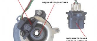
One of the most common problems with the VAZ 2109 distributor is failure of the Hall sensor. If the sensor is faulty, the engine stops starting; we replace this part as follows:
- remove the distributor from the engine;
- unscrew the cover (two screws);
- dismantle the vacuum regulator;
- unscrew the screw holding the sensor connecting block;
- unscrew the fasteners of the upper bearing holder, it is secured with two screws;
- remove the bearing assembly with the sensor, remove the Hall sensor from the holder (two screws);
- we install a new part, assemble the distributor, and put it in place.
After repairing the VAZ2109 distributor, you may need to adjust the ignition; it is done very simply:
- loosen the three nuts of the PR housing itself;
- with the engine running, gradually turn the distributor in one direction or the other, apply gas with the throttle - we find the position in which the engine picks up speed faster, without dips;
- Then we tighten the nuts and check the car while driving. If it was not possible to find the desired position immediately, repeat the operation.
Related articles:
- The importance of KBM when taking out an MTPL insurance policy The concept of KBM was introduced by the Russian Union of Auto Insurers (abbreviated RSA) in 2013, the bonus-malus coefficient (this is how the abbreviation stands for) is intended to […]
- Adjusting valves on GAZ car engines The engines of Volga passenger cars GAZ 21, GAZ 24 (or 2410), GAZ 3110, as well as trucks GAZ 53 and GAZ 3307 need valve adjustment. If the valves are not adjusted in time, they […]
- How the salenblocks of the Opel Astra H rear beam are changed The Opel Astra H passenger car model is the third generation of the Astra brand, the car was produced from 2004 to 2009. The German car model is highly reliable, chassis parts […]
Installation of contactless ignition on VAZ-2107 cars
The first step, of course, is to purchase a set of equipment for contactless ignition. We advise you to purchase an ignition kit only from trusted places. Do not forget to read the instructions for the purchased device
It is important that the contactless ignition kit matches the technical characteristics of your car
Pay attention to the length of the distributor shaft - it should not differ from the size of the shaft installed on your machine
The standard contactless ignition kit includes the following parts:
- coil;
- distributor;
- connecting wires;
- switching unit;
- four DVRM spark plugs;
- high-voltage wires (set).
To successfully install a contactless ignition system, you must follow a certain sequence of actions. The first step is to turn off the power to the car; to do this, remove the negative terminal from the battery. Next, we disconnect all the wires, including the main high-voltage wire, from our ignition coil. Now you can remove the distributor cover. We set the distributor slider to a certain position so as not to disturb the existing ignition settings. It is also necessary to place a mark on the engine block in order to correctly install the new distributor
Be sure to pay attention that the mark should be placed in the middle of the five slots that are located at the bottom of the distributor. After these manipulations, you can unscrew the nut and remove the old contact ignition distributor
Before directly installing the new distributor, you must remove its cover and place the slider in the same position as on the old distributor. Only after this can the distributor be inserted into the hole in the engine block. Next, align the marks and clamp the distributor body with a nut.
We reassemble: install the cover, screw it on and connect the wires. Now let's move on to the ignition coil. We disconnect and carefully remove the old coil, then install a new one in its place. We connect the second end of our central high-voltage wire to the coil, and put aside the brown wire that previously went from the distributor to the coil; we will no longer need it.
We put all high-voltage wires in their places. We connect two brown wires to the new coil - to contact “K”, and connect two blue wires to the contact marked “B”.
We decide on the place where the switch will be attached. You can install it near the washer reservoir. It is attached to the body using self-tapping screws. We connect the connector to the switch and tightly twist the wires with electrical tape.
We start the engine and adjust the operation of the contactless ignition system.
Video: “BSZ - contactless ignition system”
Contactless distributor
In "sevens" with a contactless ignition system, a distributor of type 38.3706 is used. As already mentioned, the design of a non-contact distributor is similar to a contact one, with the exception of the mechanism responsible for creating electrical impulses in the low-voltage circuit of the system. Here, instead of a contact group, this function is performed by a Hall sensor. As for the malfunctions of the non-contact distributor, they are the same as those of the contact distributor, therefore, it is not advisable to consider them again. But it’s worth talking about the sensor in detail.
A Hall sensor is installed in the contactless distributor instead of a contact group
Hall Sensor
The operation of the sensor is based on the phenomenon of induction. The design of the device is based on a permanent magnet and a hollow cylindrical screen with four cutouts in the form of a crown. The screen is fixedly fixed on the distributor shaft. As the shaft rotates, the protrusions and cutouts of the “crown” pass through the groove of the magnet. This alternation causes a change in the magnetic field. Signals from the sensor are sent to a switch, which converts them into electrical impulses.
The operation of the sensor is based on the phenomenon of inductance
If the Hall sensor fails, the engine may not start at all, or it starts with difficulty and runs intermittently. The sensor cannot be repaired, but you can check its functionality yourself.
Hall sensor check
There are several ways to diagnose a sensor. The simplest of them involves replacing the device being tested with a known good one. The second method is to measure the voltage at the sensor terminals using a voltmeter. Measurements are taken at terminals 2 and 3 of the device. The voltage between them should be 0.4–11 V. If there is no voltage or it does not correspond to the specified parameters, the sensor must be replaced.
The voltage between pins 2 and 3 should be 0.4–11 V
You can check the device's functionality by simulating its operation. To do this, you need to disconnect the central high-voltage wire from the distributor cover, insert a working spark plug into it and place it so that the “skirt” touches the “ground” of the car. Next, you need to disconnect the sensor connector from the distributor, turn on the ignition and connect terminals 2 and 3 to each other. If a spark appears on the spark plug during a short circuit, the sensor is working, otherwise the device must be replaced.
Hall sensor replacement
To replace the sensor, you will need to remove the distributor from the engine. The order of further work is as follows:
- Remove the cover by unfastening the latches.
- We dismantle the slider.
- Using a drift and pliers, remove the shaft coupling mounting pin.
- We remove the shaft from the housing.
- Disconnect the vacuum corrector rod.
- Using a flathead screwdriver, unscrew the two screws that secure the sensor.
The sensor is secured with two screws - Remove the Hall sensor.
Once the screws are unscrewed, the sensor can be easily removed - We install a new part in its place.
- We assemble and install the distributor in the reverse order.
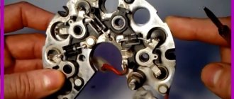
What does the distributor consist of?
A device such as a distributor includes a large number of different parts. It is not the purpose of this material to consider their purpose, but you can see what components the distributor consists of in the figure below
As can be seen from the figure, the distributor consists of several independent units. And if the purpose and operating principle of the voltage distributor unit are simple and clear, then you can familiarize yourself with the work of others in more detail. However, it is advisable to check the condition of the high-voltage distributor and slider each time the car is serviced.
Centrifugal regulator
Such a device determines the moment when fuel assemblies begin to burn in the engine cylinders. As already noted, a spark initially appears when the piston reaches the TDC position, and it is at this moment that the distributor is initially adjusted. However, two points need to be taken into account:
- Combustion of fuel assemblies occurs at a constant speed, starting from the spark plug and then spreading further throughout the volume of the cylinder. Combustion does not occur instantly, and the greatest efficiency of a gasoline internal combustion engine is achieved when the piston has passed TDC and reached BDC (bottom dead center).
- When the engine is running, the crankshaft speed changes; increasing it reduces the time required for efficient combustion of the fuel assembly.
To eliminate this contradiction, the concept of CVD is introduced, which implies the start of fuel combustion before the piston reaches TDC. The device that ensures the formation of the UOZ is a centrifugal regulator, shown in the figure; it consists of weights connected by springs and a plate.
Its operating principle is based on centrifugal force; an increase in crankshaft speed causes the weights to diverge, and through the plate - a change in the position of the cam and the runner. This will cause the contacts to open sooner and will also cause high voltage and spark to occur earlier. The fuel assembly will ignite when the piston position has not reached TDC, which will ensure its efficient combustion.
Distributors from different manufacturers have a similar adjustment of the fuel assembly ignition moment, including in VAZ 2109, 2106, 2107, 2108.
Vacuum regulator
Such a device is designed to change the SOP when the engine load changes, determined by the position of the throttle valve. The following figure will help you understand how this is done:
The vacuum regulator is a closed cavity separated by a diaphragm. One of the cavities is connected to the carburetor. The vacuum created in it, depending on the position of the throttle valve, causes the diaphragm to move. A change in its position is transmitted through the rod to the movable disk, which affects the position of the breaker cams, adjusts the time of its operation (earlier or later), and, accordingly, the ignition time of the fuel assembly.
Thus, the distributor, depending on the load on the engine, changes the moment of spark formation, affecting the characteristics of the engine. This adjustment is present in all VAZ 2109, 2106, 2107, 2108 cars, and the joint operation of the described regulators can ensure efficient engine operation over the entire range of loads and crankshaft speeds.
Octane corrector
This device allows you to mechanically change the OZ depending on the fuel used (octane number) or its quality. You can see the corrector in the figure below.
In fact, these are two plates, one is installed on the distributor and has an arrow, the other is attached to the engine, and there are marks on it. By changing their position in relation to each other, you can mechanically set the desired ignition angle. This is required mainly when using different types of gasoline.
Contactless systems and Hall sensor in the distributor
The distributor described above is a classic version and was used for many years on all cars, including the VAZ family, such as 2109, 2106, 2107, 2108. However, as electronics developed, voltage switches began to appear in which the breaker signal was used not for switching the ignition coil, but for controlling the electronics. Later, the distributor lost its mechanical breaker and was replaced by a Hall sensor.
The Hall sensor used has a fairly simple design. Yes, it must be recalled that the Hall sensor is an element that responds to a magnetic field. Therefore, the design of the sensor using Hall elements is based on this principle. To do this, a Hall sensor is located directly on the plate, on the other side there is a permanent magnet, and between them there is a rotating metal screen in which special slots are made.
When the screen blocks the field from the installed magnet, the Hall sensor has zero voltage at the output; when windows are opened instead of a solid screen, the Hall sensor generates a high voltage at the output. The distributor transmits this generated sequence of pulses to the voltage switch, and it controls the ignition coil.
In what cases is ignition installation necessary?
There are several symptoms by which a car owner can determine that it is necessary to adjust and set the ignition breaker:
- Inability to start the engine.
- Increased gasoline consumption. Of course, this may be due to the need to adjust the carburetor, but this also happens. For example, if the ignition is set later, the dynamics of the car will be low, and in order to accelerate normally, the engine needs more air-fuel mixture.
- The appearance of shots in the silencer. If the explosion follows, it will take some time for the gases to expand. In the event that the piston reaches BDC, the exhaust stroke will be next, which means that a certain part of the fuel will be transferred to the exhaust system. Accordingly, pops will appear as a result.
- The power unit began to operate noisier. and you will need to install 2106 correctly in case of shaking and tripping of the engine. The upward piston makes the operation of the power unit more rigid, and the explosion of the mixture will occur towards it.
Setting the ignition to "six"
Purpose of the mechanism
Before we tell you how a faulty distributor should be checked to identify breakdowns, let’s look at the purpose of the device. The breaker is a unit designed to detect the moment of formation of high-voltage signals in the system. The distributor is installed on both carburetors and injectors, and this mechanism is used to distribute electric ignition among the engine cylinders. That is why many car owners are interested in the question of how to set the ignition and adjust the distributor, where to turn it - this is necessary for the normal operation of the power unit.
In its design, this mechanism differs from others in the presence of various elements in the structure, which tend to wear out over time. When the first signs of malfunctions in the operation of the distributor are identified, the device must be removed and repaired, since its condition largely determines the operation of the power unit and its characteristics.
In addition to setting the ignition, the distributor performs the following functions:
- interrupts the primary ignition circuit, which ensures the appearance of a high-voltage pulse;
- distributes the spark among the cylinder spark plugs in a certain sequence.
Breaker device design
A device function called a slider
ATTENTION! A completely simple way to reduce fuel consumption has been found! Don't believe me? An auto mechanic with 15 years of experience also didn’t believe it until he tried it. And now he saves 35,000 rubles a year on gasoline! Read more"
The slider is located in the ignition distributor. You can find it right under the lid. By design, runners are quite simple devices consisting of plates (central and spacer). Despite the fact that the models of distributor runners are different, they all have the same design.
These devices have an important function regarding sparking. We can say that the proper operation of the internal combustion engine directly depends on the slider.
You should know that the distributor rotor is a part of old cars equipped with a carburetor engine system. The slider is made of plastic and has a high-voltage contact inside. When the distributor operates and rotates, the contact of the slider is in direct contact with the contacts of the cover. Thus, the spark that is so necessary for the car is set.
In technical terms, the distributor rotor is needed to transmit high voltage current. The transmission goes from the ignition coil to the spark plugs through armored wires.
The rotor is fixed directly to the distributor drive (shaft), and the rotation is set in such a way that for 1 revolution of the runner there are 2 revolutions of the crankshaft. It is in this way that the discharge is transmitted to the spark plugs in a strictly defined order.
On a distributor drive, the slider is fixed rigidly so that it does not jump off when the shaft rotates. When rotating, the side contact of the rotor contacts the CG (contact group) pressed into the distributor cap.
Interesting. The distributor cap is in the same position regularly. It does not move, but the sliding contact, “running” next to the electrodes of the cover, forms an alternating and short-term electric arc. This also explains the transmission of the discharge.
On some cars, ignition systems have two working contacts on the slider. This is, in principle, a working classic Twin Spark ignition circuit from the Italian company Fiat. One of the contacts is implemented closer to the center, the other - as far as possible. In this way, the contacts correspond to the cover electrodes, packaged according to the same principle. And most importantly: this scheme ensures complete isolation of the CGs from each other.
Twin Spark is considered one of the first systems used for effective afterburning of fuel in the combustion chamber of a car. The system has a simple design, but is very effective and economical.
Types of faults
As a rule, if the distributor slider is in order, then the car engine starts the first time, without any problems. But when difficulties are observed with the plant, this indicates a damaged or broken rotor (provided that the problem is not elsewhere).
The most common malfunction of the distributor slider is its breakdown. It can be external or internal. Obviously, the external one is determined by noticeable signs - a black mark, the internal one must be checked by the presence of a spark (details below).
The breakdown occurs due to metallization of the channel. For preventive purposes, metallization should be checked regularly. This is done using a multimeter or other similar device. The channel is checked for moment of resistance. The probes of the device are connected to the place of the slider where there is doubt about breakdown.
You should know that the spark can escape either completely or partially through the formed channel.