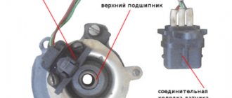
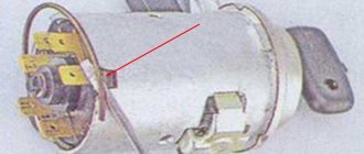
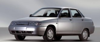
Pinout of the ignition switch VAZ-2101 VAZ-2107
The ignition switch on these cars is located to the left of the steering column. It is fixed directly to it using two fixing bolts. The entire mechanism of the device, except for the upper part in which the keyhole is located, is hidden by a plastic casing.
On the visible part of the ignition switch housing, special marks are applied in a certain order, allowing inexperienced drivers to navigate the lock activation mode when the key is in the hole:
- “ ” – a mark indicating that all systems, devices and instruments that are turned on using the lock are turned off (this does not include the cigarette lighter, interior lighting, brake light, and in some cases the radio);
- “I” is a mark informing that the vehicle’s on-board network is powered from the battery. In this position, the key is fixed independently, and electricity is supplied to the ignition system, to the electric motors of the heater and windshield washer, instrumentation, headlights and light signaling;
- “II” – engine start mark. It indicates that voltage is applied to the starter. The key does not lock in this position. If you release it, it will return to the "I" position. This is done so as not to subject the starter to unnecessary loads;
- “III” – parking mark. If you remove the key from the ignition in this position, the steering column will be locked with a latch. It can only be unlocked by inserting the key back and turning it to position “0” or “I”.
The ignition switch has five contacts and, accordingly, five terminals, which are responsible for supplying voltage to the desired unit. All of them are numbered for convenience. Each pin corresponds to a wire of a certain color:
- “50” – output responsible for supplying current to the starter (red or purple wire);
- “15” – terminal through which voltage is supplied to the ignition system, to the electric motors of the heater, washer, and instrument panel (double blue wire with a black stripe);
- “30” and “30/1” – constant “plus” (pink and brown wires, respectively);
- “INT” – external lighting and light signaling (double black wire).
Color gradation
To correctly connect the contacts on the back side, you need to know the colors of the wires. Each of the chips comes with a cable with insulation of a personal shade. We recommend focusing on the diagram:
- pin 50 – contacts the red wire connected to the starter;
- pin 30 – pink contact;
- pin 30/1 – brown cable;
- pin 15 – blue with a dark stripe is in contact with the heater, ignition, etc.;
- INT pin – black cable, responsible for starting the head optics and operating the dimensions.
After all the wiring is connected, we can reconnect the battery terminals and check the functionality. We start the ignition in each position one by one, testing the performance of the devices.
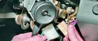
Replacing the ignition switch contact group on VAZ 2110 and 2112. When you need to start the first time
- Remove the cover from the steering column. To do this, you will need a Phillips screwdriver;
- Disconnect the connector with wires from the ignition switch;
- The next step is to remove the lock itself. Some difficulty arises here; for safety reasons, the manufacturer made the heads of the bolts securing the lock break off. Therefore, you can’t just unscrew them. To do this, take a thin chisel and, pushing it towards the unscrewing side, tear the bolts out of place. Then you can unscrew them using simple pliers;
- Remove the mounting bracket and the lock itself from the steering column.
- Now you can repair this part. Replacing the contact is done as follows:
- Unlock the clamps using a screwdriver;
- Extract the contact group.
AutoFlit.ru
Precautionary measures
Nuances that must be taken into account when replacing the lock and adjusting the ignition timing:
- All repair operations are performed with the battery disconnected. Otherwise, you may cause the contacts to short-circuit, which will lead to equipment failure.
- If the engine is warming up in the garage, be sure to open the door. In an enclosed space, high-quality ventilation must be implemented.
- Do not touch the crankshaft while the engine is running, especially if work is carried out while wearing a shirt. The sleeves of clothing must be rolled up to prevent it from being caught by the pulley.
- When disconnecting the wires from the distributor, the contact elements cannot be connected to each other; the same applies to the battery. This will lead to serious problems in the on-board network, as well as breakdown of electrical devices.
Changing the contact group
Exploded view of the lock
Based on price considerations, replacing one contact group is less expensive:
- All our actions are repeated in principle, as in the case described above with removing the lock, you will have to remove the casing, and so on
- To avoid the widespread problem associated with mixing up contacts, it is recommended to number them before disconnecting (or mark them in some other way)
- This measure will save your nerves and time.
- Some models of locks have a locking ring in their contact group, and here we need an awl to pull it out
- It’s important not to forget to stick it in place later
- Then everything is put back together and screwed to the control column
conclusions
Differences in vehicle modifications often lead to confusion when servicing electrical components. This is why when servicing yourself it is so important to use the original diagram related to a specific car model. This will not only avoid problems, but will also make troubleshooting easier.
Free reference material on the electrical equipment of the domestic VAZ-2105 car is presented. Including a relay and fuse block, as well as diagrams of some modifications. The electrics are made according to a single-wire circuit - the negative terminals of the sources and consumers of electricity are connected to the “ground” of the car, which serves as the second wire. Most circuits are turned on by the ignition switch. The car diagram is presented in two parts in the figures. Click to enlarge to full screen.
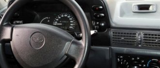
Replacing the ignition switch on a VAZ car
To carry out repair work to replace the ignition switch of a vase, we will need: a screwdriver, a tester and a thin awl. Once you have everything you need, you can begin the repair. On all classic VAZ cars, the ignition switch is located at the bottom, on the left of the steering column. To replace you need:
- Disconnect battery
- Remove the plastic casing by first unscrewing the screws that secure it.
- Then unscrew the two screws securing the ignition switch to the bracket.
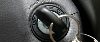
- We insert the key and set it to position 0 to disable the anti-theft device.
- Insert the awl into the hole in the bracket and press the latch. Then we take out the lock itself.
- After removal, it is recommended to mark the contact wires so that nothing is mixed up the next time you connect.
Removing the ignition switch on a VAZ-2106 begins with disassembling the steering column casing. We unscrew the five bolts and remove its halves. Before you begin disassembling the electrical part of the lock, it is very useful to disconnect the battery by removing the negative terminal or unscrewing the switch bolt. After this, remove the spring retaining ring from the back of the lock body and remove the contact group. We move it to the side so that it does not interfere, and we begin to remove the lock itself.
It is secured in the steering shaft bracket with two bolts, after unscrewing which nothing happens. It is useless to try to remove the lock from its socket if you do not know about the special stopper. It is located on the lock body under the bracket. We press this stopper into the lock with a thin screwdriver through a small hole in the bracket. Further, according to all the instructions, the lock should be pulled out freely, but this does not work.
Potential problems
Possible troubles are often related to the mechanical part. They are manifested in the following factors:
- the key fits tightly into the “secret”;
- it is not possible to make a turn the first time;
- It is problematic to remove the key from the cylinder, etc.
If you ignore such signals, it may result in breakdown. As a result, you will have to spend money on restoring the mechanism or replacing it.
In some cases, the use of special chemicals may help. One of them is WD-40 fluid. Brake fluid can replace it, which also helps delay repairs for a while.
In addition to mechanical breakdowns, motorists have problems with the electrical part . They manifest themselves in burning contacts or breaking the circuit. It is believed that the most vulnerable pinout of the VAZ-2107 ignition switch is at the starter connection terminals. In such a situation, no operation occurs either on the first attempt to turn, or on subsequent attempts.
Every motorist can test the functionality of the contacts independently by measuring the voltage on the contacts with a multimeter or voltmeter.
When faults are detected in the contact group, a complete replacement of the lock is not always required. It is enough to replace the electrical part of the lock even without completely dismantling the cylinder.
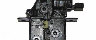
Replacing the lock cylinder itself or the contact group
Read
Replacing the VAZ 2109 lock cylinders requires the following tools:
In case of any breakdown, it is not necessary to completely replace the lock; if the cause of the malfunction lies in replaceable parts, then a partial repair of the lock is carried out and replacing the lock cylinders on the VAZ 2109 makes sense when the key stops spinning freely in the keyhole. Another option for partial repair is to replace the contact group; this requires a minimum of tools and little understanding of the device.
Our summary will help you understand the device:
- Nothing and no one forbids you to change the entire lock every time, and even go to a service station if you are satisfied with the price
- After removing the casing, access to the switch lock is revealed.
- In principle, the lock cylinder can already be removed at this step
- Therefore, we pull out the side pin that holds it in the lock
- This is easy to do with a narrow screwdriver (clockwise) while tapping it with a small hammer
- If the pin cannot be pulled out this way, then try to carefully drill out the cylinder using a narrow drill
- If it is more convenient for you to pull it out first, pull out the ignition switch, before you start replacing the cylinder, to do this you need to unscrew the bolts securing the ignition switch to the control column
- This must be done using a hammer and chisel because these bolts have sheared heads.
- You need to loosen them a little with a chisel, and then unscrew them with pliers, as in the photo below
Differences from the base model
The choice of the “five” was not accidental - in those years it was a more modern solution to the car’s design in technical terms. This was presented in every possible way in the videos of those years. But even having decided to produce a station wagon based on it, the engineers had to make changes to some components.
- Instrument panels;
- Rear blocks of side lights and brake lights;
- Injection fuel supply system for a model with a VAZ 21067 engine.
Accordingly, the VAZ 2104 engine compartment wiring diagram for the injector had design differences from the standard carburetor version.
Dashboard
An experimental panel with combined instruments was installed on a VAZ 2104 car.
In particular, a single device (in the diagram under No. 7) consisted of:
- Low battery level indicator;
- Fuel level indicator in the gas tank, combined with a warning lamp;
- Engine oil pressure warning lamp;
- Coolant temperature gauge with level indicator lamp in the expansion tank.
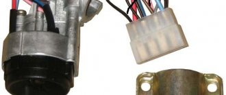
Pinout of lock VAZ-2108, VAZ-2109, VAZ-21099
Pinout according to the old type
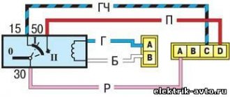
Pinout of the VAZ-2109 ignition switch with unloading relay:
- comes +12V in position I, II, III (parking)
- comes +12V in position I, II, III (parking)
- comes +12V in position III (parking)
- position I, +12V goes out after turning on the ignition (contact 15/2), disappears at start (II);
- position I, +12V goes to the starter (pin 50);
- position I, +12V goes away after turning on the ignition (pin 15), does not disappear when starting II;
- +12V comes from the battery (pin 30);
- comes +12V constantly.
New pinout type
Pinout of the new VAZ-2109 ignition switch:
- comes +12V constantly
- comes +12V constantly
- +12V arrives after turning on the ignition (pin 15), does not disappear when starting II;
- +12V arrives after turning on the ignition (contact 15/2), disappears at start (II);
- position I, +12V goes to the starter (pin 50);
- +12V arrives after turning on the ignition (pin 15), does not disappear when starting II;
- +12V comes from the battery (pin 30);
- comes +12V constantly.
Precautionary measures
Nuances that must be taken into account when replacing the lock and adjusting the ignition timing:
- All repair operations are performed with the battery disconnected. Otherwise, you may cause the contacts to short-circuit, which will lead to equipment failure.
- If the engine is warming up in the garage, be sure to open the door. In an enclosed space, high-quality ventilation must be implemented.
- Do not touch the crankshaft while the engine is running, especially if work is carried out while wearing a shirt. The sleeves of clothing must be rolled up to prevent it from being caught by the pulley.
- When disconnecting the wires from the distributor, the contact elements cannot be connected to each other; the same applies to the battery. This will lead to serious problems in the on-board network, as well as breakdown of electrical devices.
The structure of a car ignition switch
- Locking rod
- Frame
- Roller
- Contact disc
- Contact sleeve
- Block
- Protrusion of the contact part.
The lock mechanism is connected to many wires. They continue from the battery, connecting all the electrical devices of the car into a single chain. When you turn the ignition key, the electrical circuit is closed from the “-” terminal of the battery to the ignition coil. As a result, the current passes through the wires to the ignition switch, through its contacts it is directed to the induction coil, after which it returns back to the “+” terminal. As electricity passes through the coil, it generates high voltage, which it transmits to the spark plug. Therefore, the key closes the contacts of the ignition circuit, thereby starting the car engine.
Features of the electrical equipment of the VAZ 2105 car
The electrical equipment of the VAZ-2105 car is made according to the classic single-wire circuit for the Zhiguli family, in which:
- the metal body of the car plays the role of a second wire;
- the negative terminals of all electrical devices and components are connected to ground;
- electrical circuits are protected by fuses;
- the operation of the main systems is activated through the vehicle's ignition switch.
For reference: the ignition switch controls electrical networks by supplying power from the battery or generator. The contact group of the lock is designed in such a way that when the engine starts, the electrical wiring of the VAZ 2105 secondary circuits is turned off.
Egnition lock
The ignition switch was used as a control system for the vehicle's electrical systems, which had four main positions:
For reference: the factory instructions inform you that, regardless of the position of the key, the interior lighting lamps, brake light lamps (when the brake pedal is pressed), the horn and the connector for connecting a portable lamp remain energized.
Fuse and relay box
To protect electrical circuits and devices, a fuse circuit is used to break the electrical connection. This happens when the voltage increases - the fuse-link melts due to temperature and the circuit is disconnected.
The photo shows:
- From 1 to 17 – fuses;
- Relay 18 is responsible for turning on the low beam headlights;
- Relay 19 is responsible for turning on the high beam headlights;
- Relay 21 activates the headlight cleaner and washer;
- Relay 22 is responsible for turning on the heated rear window.
For reference: under No. 20 the jumper is indicated. The wiring diagram of the VAZ 21053 in the export version is distinguished by the installation of a relay for turning on sound signals in this place.
Headlight unit
The main and most noticeable difference from the classic Zhiguli models of the VAZ 2105 were the headlights. It was their massive appearance that gave the car a modern look. And the ability to remotely adjust the direction of the light beam was completely new.
For these purposes, several main and additional devices were used, among which a new product was the hydraulic headlight corrector.
His role was as follows:
- When the car was loaded, the rear part of the body lowered;
- The luminous flux of high and low beam headlights began to blind oncoming vehicles;
- With the help of a hydraulic corrector, the driver could lower (tilt) the headlights without leaving the car.
Thanks to this, the problem of driving safety in the dark was solved.
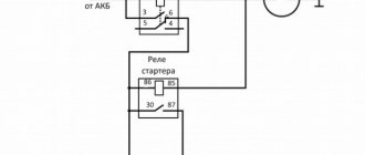
Installing the "Start" button
Some Kopek owners tune the ignition system of their cars by installing a “Start” button instead of the standard ignition switch.
But what does such tuning give? The essence of such modifications is to simplify the process of starting the engine. With a button instead of a lock, the driver does not need to poke the key into the lock, trying to get into the cylinder, especially without the habit and without lighting. In addition, you don’t need to carry the ignition key with you and worry about losing it. But this is not the main thing. The main thing is the opportunity to enjoy the process of starting the engine with one press of a button, and also to surprise the passenger with this.
Using this button, you can start the engine without the ignition switch and key.
In automobile stores you can purchase a kit for starting a power unit from a button for about 1,500–2,000 rubles.
A kit for starting an engine with a button can be purchased at auto stores.
But you can save money and assemble an analogue yourself. To do this, you only need a toggle switch with two positions and a button (not recessed), which will fit the size of the ignition switch housing. The simplest connection diagram is shown in the figure.
The toggle switch and button can be installed in any convenient place
Thus, by turning on the toggle switch, we supply voltage to all devices and to the ignition system. By pressing the button, we start the starter. The toggle switch and the button itself, in principle, can be placed anywhere, as long as it is convenient.
As you can see, there is nothing complicated either in the design of the VAZ 2101 ignition switch or in its repair. If it breaks, you can easily repair or replace it.
Why is it needed?
Self-replacement of the ignition switch of a VAZ 2110
As soon as cars appeared, there was no ignition key, and the engine was started using a curved element for the engine, which was quite large and stuck in the front or back of the car. Thus, it turned out that the engine was started manually in the literal sense.
Now this function has been inherited by the starter, which turns the internal combustion engine by the flywheel - a large flat disk with teeth. This disc is located between the engine and the clutch.
This does not happen without the participation of battery power, of course.
The ignition switch is a device that, when turned on, ensures the supply of electric current from the battery to the traction relay. This is a kind of first push to move the vehicle. Therefore, the ignition switch is an important element, and when it breaks, replacement cannot be avoided, and in order to install a new one, you need to remove the old one.