Useful tips
Author: Anastasia Safonova12/27/201612/27/2016
The VAZ 2110 ignition switch cannot be called a reliable part, especially when you compare its service life with the same devices on cars of foreign origin. Therefore, owners of the tenth - twelfth model, who use the car for a long time, sooner or later encounter problems with the lock and its repair. On the other hand, the element can be easily removed from the car and every skilled motorist can replace it. But first you should figure out whether the entire part needs to be replaced, since in most cases it can be repaired.
- Instructions for removing the element
Dismantling the VAZ 2110 lock in the photo - Training video on replacing the ignition switch
Reasons for replacing the ignition switch
There are 3 main reasons leading to breakdowns of this device:
- mechanical wear as a result of long-term use;
- problems with the electrical part of the lock;
- damage due to attempted break-ins and car theft.
Reference. The first troubles associated with turning on the ignition and starting the engine may appear after three years of operation of the VAZ 2110-2112.
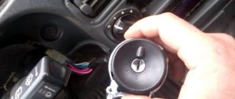
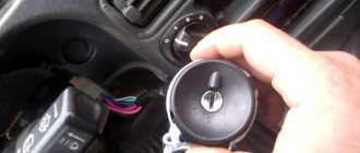
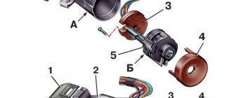
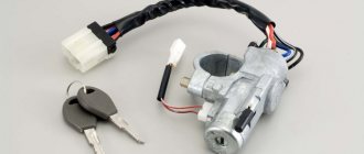
Appearance of the ignition switch VAZ 2110—2112
Not every one of the listed reasons leads to a complete replacement of the element; sometimes you can get by with “little loss” by changing one of its parts. To determine this issue, you need to diagnose the signs of a malfunction:
- Contacts are burnt or oxidized. In this case, the mechanical part works, but the electrical part does not. The problem is solved by cleaning or replacing the contact group.
- The key gets stuck in the slot, after starting the engine it is not thrown back and you have to turn it by hand. These are malfunctions of the core (larvae) and the ejection spring, which can be completely repaired.
- Obvious mechanical failures of the locking tongue (the steering wheel is very difficult to rotate), jamming or cracks in the housing are a reason to replace the entire ignition switch.
In the event of a mechanical failure, the key may not turn or may not be released by the spring.
A separate issue is the loss of all keys by the owners. It can be solved in two ways - by replacing the entire device or the key turning mechanism - the cylinder. For obvious reasons, the second option will be cheaper, especially if you do the work yourself.
Reference. As practice shows, the mechanical insides of an element can be broken by an ignorant driver who has lost his keys and is trying to unlock the steering wheel in order to start the engine by shorting the wires. There is a more elegant way - to remove the lock, and only then connect the wires of certain colors, as described below.
Checking the lock contact group with a multimeter
A faulty contact group can be easily diagnosed if you have a multimeter or other device with a resistance measurement function in your household. To do this, you need to get to the connector located under the plastic frame of the steering column and disconnect it. Then use a multimeter to measure the resistance between all contacts in the block, turning the key to different positions. Depending on the result, the following conclusions are drawn:
- the device shows infinity - the contact group is out of order and needs to be replaced;
- some resistance value indicates burnt or oxidized contacts, try to clean them;
- zero readings on the device indicate that the electrical part is fully operational.
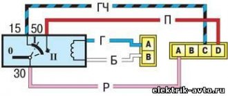
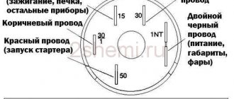
VAZ 2110 ignition switch diagram
Important! You need to measure the resistance in the block whose wires come from the ignition switch (male connector), do not confuse it with other contacts connected to the car’s on-board network.
How does the ignition switch of a VAZ 2110 work?
The lock is located on the left of the steering column. The lock body is hidden by a plastic casing, only the key slot is visible, and the wires are located at the bottom.
When the key is turned, the contact disk also turns, which activates the electrical circuits.
The ignition switches have the following positions:
- "Switched off". Marking "0".
- "Ignition". Marking "I".
- "Starter". Marking "II".
- "Blocking". Marking "III"
The key must be inserted and removed from the “I” or “III” position.
From the “Blocked” state to the “Off” marking, the electric field is short-circuited in the structure of the machine (additional devices, light, stove)
The “Starter” position is self-starting and the engine is brought into working condition. When the engine starts, you need to switch to the “Ignition” marking.
To turn off the engine, you need to turn the key to the left, marked “Off”.
Instructions for removing the element
For disassembly you need to prepare a simple set of tools:
- 10 mm head and ratchet drive;
- Phillips screwdriver;
- narrow chisel (width 5-8 mm);
- hammer;
- round nose pliers with tapered, curved ends.
Ignition switch replacement tool
To successfully install a new or repaired lock in place, it is advisable to purchase 4 special fastening bolts with M6 threads with a head size of 10 mm and a length of 20 mm. Their feature is the heads that come off with a key at a certain tightening torque. After tearing off the heads, semicircular caps remain on the surface, which are much more difficult to unscrew for an untrained person. But you will have to do this during disassembly.
The battery must be disconnected before starting work.
Like any event related to tampering with the electrical part of the car, dismantling the ignition switch begins with disconnecting the negative terminal of the battery. Then proceed in this order:
- Using a Phillips screwdriver, remove the screws holding the two halves of the plastic frame of the steering column together.
- Lower the handle that fixes the position of the steering wheel during adjustment all the way down and remove the plastic panels. Disconnect the ignition switch block and carefully cut the tape connecting your bundle of wires to the common harness. In order not to cling to the steering column switch during operation, it can also be pulled out of the connector.
- On the metal casing of the steering column you will see a lock mount consisting of two clamps. They are held together by 4 bolts with the heads torn off (visible on the left side). Pointing the chisel at the semicircular caps, use a hammer to loosen the tightening of these bolts one by one.
- Using pliers and then your hands, unscrew all 4 bolts and remove the ignition switch.
Unscrewing the plastic steering column cover
Note. There are “dozens” in which not all the bolt heads are torn off during assembly. This simplifies the matter; the fasteners can be easily unscrewed with a 10 mm socket.
Bolts with intact heads can be unscrewed with a wrench
At the stage of disconnecting the connectors, it becomes possible to check the functionality of the contact group by measuring resistance, as described in the previous section. If you remove the lock due to the loss of the keys and want to move on, then after dismantling you need to do the following:
- On the “mother” block, which remains hanging after the lock is turned off, find contacts with thick wires of purple and blue color (the latter with a black stripe).
- Connect these terminals with any conductor, after which the ignition will turn on.
- The thick red wire leads to the starter. To start, its contact must be temporarily connected to the installed jumper. When the engine starts, the red wire must be disconnected.
This is how jumpers are inserted into the block to start the engine without a key.
Advice. It is more convenient to look at the colors of the conductors on the harness of the removed device, and then find them on the “mother”.
After unscrewing the fasteners and disconnecting the wires, the lock can be easily removed from the car
Assembly is carried out in the reverse order, but taking into account the following precautions:
- do not tighten the fastening bolts until you have accurately aligned the position of the lock on the casing so that the facing plastic panel fits smoothly into place;
- before final tightening the bolts, make sure that the lock snaps into place when turning the steering wheel, otherwise adjust the position of the lock;
- The tightening torque should be such that the heads of the new bolts come off and the round heads remain.
When installing and tightening the bolts, their heads should come off
If you think that special fasteners are not an obstacle for car thieves, then you can screw in regular bolts with M6 threads and carefully tighten them.
Dismantling the VAZ 2110 lock in the photo
This connector must be disconnected to remove the lock.
The steering column switch is easily removed from its socket
Appearance of the mount. It can be seen that not all the bolts are broken
Bolts without heads are torn out of place with a chisel
After unscrewing, the left mounting clamp is removed
The lock with the right clamp is held on by wires that need to be disconnected
After breaking the bolts with a chisel, they can be easily unscrewed with pliers
Training video on replacing the ignition switch
Order of Operations
It is worth immediately noting that independently replacing the ignition switch cylinder of VAZ 2110, 2111 and 2112 is problematic. This part is difficult to find on sale, and working with it requires special skills. An incorrectly performed operation will result in unstable operation of the ignition system. In this case, you need to purchase the assembly and change it completely:
- Since there is work to be done on the on-board electrical system, you need to disconnect the battery; to do this, disconnect the negative terminal of the battery. In addition, it is rational to provide good lighting in the work area, so you will spend less time performing operations.
- Now you need to lower the steering column all the way and remove the plastic casing, after unscrewing the screws.
- Using a chisel, unscrew the bolts with cut heads and pull them out with pliers. Hammer blows should be directed clockwise.
- Now you can remove the bracket and the lock itself from the steering column by disconnecting the electrical connector.
- If the backlight lamp needs to be replaced, the contact is disconnected and its socket is removed with pliers. Installing a new device.
- To replace the contact group of the ignition switch of a VAZ 2110, 2111 or 2112, the clamps are released.
- If the microswitch stops working, unscrew the screws, remove the rod, and pull out the latch. We install a working device.
- We replace the contact group of the ignition switch of VAZ 2110, 2111 or 2112.
- Now the operations are performed in reverse order. We install the assembled unit on the steering shaft, clamp it with a strap and tighten it with bolts. They need to be screwed in all the way; for this you can use a 10mm spanner or a socket with a knob. IMG8
- Without breaking off the heads from the fasteners, we begin to adjust the steering wheel: the key is located opposite the I icon, and the steering shaft is in the same position. If the shaft does not lock and the steering wheel continues to rotate freely, you need to find the correct location of the lock so that its latch engages the groove in the shaft.
- Now you can break off the heads from the bolts.
- Once again we test the functionality of the mechanism. If everything is in order, you can connect the contacts.
- We connect the lock with the battery by replacing the negative terminal. And again we test the performance of the node. If the results are positive, the decorative plastic casing is mounted in its original place.
Failure of the lock may be due to normal oxidation of the contacts in the group. In this case, you only need to clean with fine sandpaper. This malfunction can be determined using a multimeter in ohmmeter mode. Each pair must be tested for short circuits.
Repair of the ignition switch for VAZ 2110, 2111 and 2112 can be seen in this video:
This is interesting: Replacing generator bearings on a VAZ-2110 - which bearings?
Replacing the contact group
In the event that, as a result of diagnostics, a malfunction of the contact group is detected, you will still have to remove the ignition switch, since it will not be possible to get to it in any other way. After removing the element, disassemble it using the following algorithm:
- Disconnect the connectors with the backlight power wires.
- Remove the decorative plastic cover by releasing the 4 latches. Work carefully because these clips are easy to break off, and buying a cover separately is quite a task. It is not advisable to change the entire lock because of it.
- By bending the 2 clamps holding the contact group, remove it from the ignition switch.
The plastic cover can be removed using a screwdriver
Note. You will additionally need a small flat-head screwdriver as a tool to bend the latches.
The contact group is located immediately under the cover
First of all, examine the status of the contacts. If they have darkened (oxidized), then clean the current-carrying surfaces with fine sandpaper P1000. Then put the group in place and, without installing the lock, connect it to the vehicle's on-board electrical system to check its functionality. If unsuccessful, the part must be replaced. The same will have to be done if the contacts are burnt or the group does not work without any external signs of malfunction.
The part is removed after bending two latches
Information about the ignition system that every motorist should know
Ignition switch contact group for VAZ 2110
The main most significant functions of ignition systems:
- activation of the engine “core” of the car;
- protection of unauthorized engine activation;
- providing a number of auxiliary functions, etc.
From a practical point of view, the ignition system is the on/off switch for the car’s engine, and if this system is in a faulty state, the likelihood of the car being stolen will increase significantly.
The main reasons that force you to replace the car’s ignition system
- detection of traces of an unauthorized attempt to start the engine;
- in case of involuntary loss of the ignition key;
- contact group malfunction.
Contact group of the ignition switch for VAZ 2110
A simple way to check if poor contact closure is the reason why your car's ignition system refuses to start:
- first you need to disconnect the negative terminal, which is located on the battery;
- remove the casing from the steering column;
- then disconnect all contacts;
- check the voltage level using an ohmmeter;
- the charge of all contacts being tested must be at zero level.
Note. If during the test the ohmmeter shows a value other than zero, the ignition switch must be replaced immediately.
Ignition switch contacts VAZ 2110
It is necessary to objectively understand that if the integrity of the ignition switch has not been compromised, then it makes sense to replace only the contact group (cylinder (see VAZ 2110 lock cylinder and its replacement)). This procedure may be necessary if an attempt was made to steal the car or if the contact group has oxidized during long-term use.
Installation of a new larva
To replace the lock core due to mechanical failure, remove it from the vehicle as described above. Then follow this algorithm:
- Insert the key into the slot and use a Phillips screwdriver to unscrew the 3 screws holding the 2 halves of the lock body together.
- Separate the housing while holding it with the key facing up. If you hold the lock in a different position during disassembly and do not insert the key, the insides will spill out and you will not understand how to put them back together. In this case, the ball with springs may get lost.
- Remove the locking mechanism, which consists of two spring-loaded parts, and pull out the spring itself.
- After removing the key, carefully remove the core so that the ball with the spring (located on the side of the cylinder) is not lost.
To disassemble the case, you need to unscrew 3 screws
Before replacing, it is necessary to remove the return spring from the old cylinder, since it is not sold complete with a new core. The spring is inside the part on the back side in a cocked state; it must be installed in the same form on the new cylinder. Also, do not forget to remove the thin spring from the hole where the ball is inserted.
The locking mechanism tongue peeks out from the bottom of the case
Important point. Remember that if you replace the core because it is broken, the new key will no longer fit the door lock. There are 2 options: use two separate keys or simultaneously change the cylinder in the door. The last method becomes the only applicable one when all the keys are lost.
The larva must be pulled out so as not to lose the details
When installing the core, you need to move the spring for the ball into the hole and insert the part into the body. Then push the larva all the way, while simultaneously inserting the ball into the socket. After that, all that remains is to assemble the locking mechanism and tighten the housing with screws. When finished, check the operation of the ignition switch by turning the key to different positions.
The ejection spring from the old core needs to be moved to the new one
How the larva changes - video
The video demonstrates how to disassemble the mechanical part of the ignition switch of a VAZ 2170 (Lada Priora), but in design it does not differ from the elements installed on VAZ 2110-2112 cars.
As a rule, there is no need to change the entire ignition switch, although car enthusiasts often resort to this option to save time. The operation will take the technician at the service station no more than 20 minutes. Replacing it yourself will require more time, but you will be able to replace only the broken part (cylinder or contact group), thereby saving personal funds.
Source
