VAZ 2110 on-board system unit
The on-board control system of the VAZ 2110 is represented by several sensors and alarms that help eliminate deficiencies in the operation of the vehicle system. At one moment they may no longer be necessary, and at another they can save a person from unexpected breakdowns or even save a person’s life. Their serviceability must be constantly monitored. In order for the on-board display unit of the VAZ 2110 control system to always remain in working condition, you need to know the number of sensor data.
On-board control system of the VAZ 2110 and its purpose
VAZ 2110 on-board system unit
The VAZ 2110 on-board control system is represented by several sensors and alarms that help eliminate deficiencies in the operation of the vehicle system. At one moment they may no longer be necessary, and at another they can save a person from unexpected breakdowns or even save a person’s life. Their serviceability must be constantly monitored. In order for the on-board display unit of the VAZ 2110 control system to always remain in working condition, you need to know the number of sensor data.
Purpose of the MAZ block
Thanks to the modern BSK 4 MAZ (multilayer printed circuit board), the electrical equipment circuits of Belarusian trucks are protected from overvoltage.
The manufacturer of the part is JSC MPOVT.
The high quality of the block meets international standards.
Thanks to well-established production and the use of the latest technologies, the BSK 4 MAZ unit has the following characteristics:
- Voltage - 24 ±6 V;
- The operating mode of the part is nominal S 1;
- Complies with GOST 3940;
- Temperature range – from -55 to +60 degrees Celsius;
- There is a function of increased protection against the ingress of liquid, dust and other foreign bodies;
- Weight – 6.8 kg.
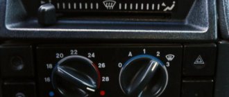
Top part
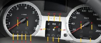
So let's start from left to right. First, the top part of the control panel:
- Side scale from 50 to 130 and arrow. Shows the temperature of antifreeze (antifreeze) in the engine cooling system;
- Almost round scale (0 – 80) and arrow. Tachometer showing engine speed;
- Two arrows at the top, almost in the middle of the control panel - turn signals (right, left);
- Speedometer. Well, this device, probably everyone knows, shows the speed at which the car is moving;
- A side scale with an arrow and, most often, two images of a filling column (white and red). Instead of a red column there may be a yellow light. This is an indicator of the fuel level in the tank. If the red column (yellow light) lights up, it means that there is very little fuel left in the tank - no more than 7 liters, urgent refueling is required.
Additional panel
The additional front panel of the new-style BSK control has indicators:
- An oil can is shown. If the light works, check the oil level;
- An icon lights up, which, with some imagination, can be “identified” as working wipers. This indicates that there is not enough windshield washer fluid in the tank;
- Conventional image of a thermometer over a container with liquid - high temperature of antifreeze;
- A crossed out light, which the arrow points to, is a sign that the brake light or parking lights are not working;
- If the light with the image of a wheel with brake pads lights up, it is quite possible that the pads are worn out and require replacement;
- The sign of a man with a seat belt indicates that the seat belt should be fastened.
System problems
Summarizing the experience of drivers, the most common problems occur in the ignition switch. The limit switch in it should receive 12 volts. Sometimes it is the installers who confuse the diagram, after which the BSK not only does not see the door, but also does not work at all. To check functionality, you must disable the limit switch. If the BSK turns on, but does not see the door, then the problem is here.
For other cases, you will have to resort to checking the systems one by one according to the pinout diagram:
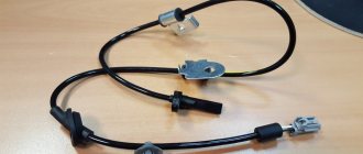
- Replacement and diagnostics of the coolant temperature sensor (DTOZH) VAZ 2114
- Checking and replacing the mass air flow sensor (MAF) on a VAZ 2114
- Outside air temperature sensor for VAZ 2114: purpose, causes of failure and ways to eliminate them
good afternoon, AM 2114 8 class. I encountered a problem, after starting the car the bsk started to light up just dimly (all diodes). Can anyone tell me what the problem is? Also, with each shutdown and start-up, the instantaneous mileage and clock began to reset to 00.
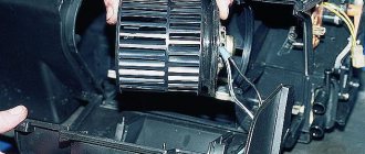
Connecting the trip computer
The mentioned diagram took into account only one, brown wire leading from the red block to the trip computer, but this is clearly not enough. Therefore, let's see how the pinout occurs here.
- The fuel consumption signal from the electronic control unit is indicated by a green wire;
- Orange leads to terminal “15” in the ignition switch;
- Red and white - to terminal “30” in the ignition switch;
- Black, which is common, goes to ground;
- The speed indicator corresponds to brown;
- The positive terminal of the fuel sensor is green and red;
- Responsible for lighting the dashboard white, it leads to the light control.
Make sure that the board is not damaged, on which, in fact, uninterrupted reading of information from your VAZ 2110 depends, and providing it to you through all those sensors and devices that you always see in front of you.
All malfunctions of the ignition switch VAZ-2110
The ignition switch is a very important part that combines many functions. Its malfunctions on the “ten” are also varied and require a clear description.
The ignition switch on any car performs at least three functions: switching electrical circuits, access to starting the engine using a key, and locking the steering shaft for anti-theft purposes. On the “ten”, protection against restarting the starter, a forgotten key indication signal and illumination of the cylinder are added to this list.
Let's look at how it all works point by point and... breaks down!
The ignition switch contact group does not work
A contact group is a structure that closes various electrical contacts, depending on the position of the key in the lock. It is located in the back of the lock body and is capable of presenting unexpected surprises. If the contact group malfunctions, strange at first glance electrical problems arise in the car - for example, the headlights may fail, or the heater may stop working. A faulty contact group may also make it impossible to start the engine. In detail - in the article there are signs of a malfunction of the ignition switch contact group.
VAZ-2112 wiring diagram
Wiring diagram for a car in a hatchback body (click on the picture to enlarge)
Designations: 1 – Headlight, 2 – Horn, 3 – Main radiator fan, 4 – Starter, 5 – Battery, 6 – Generator, 7 – Gearbox limit switch (reverse), 8 – Actuator in the front passenger door, 9 – Relay power windows permissions, 10 – Starter relay, 11 – Heater fan, 12 – Electric heater partition drive, 13 – Main pump, 14 – Washer reservoir sensor, 15 – Driver’s door actuator, 16 – Front passenger window selector, 17 – Fifth wheel release button doors, 18 – Heater fan resistance unit, 19 – Main wiper motor, 20 – Driver's window lift selector, 21 – Front passenger's window lift motor, 22 – Central locking, 23 – Exterior light switch, 24 – Brake fluid leakage sensor, 25 – Additional pump , 26 – Driver's window lift motor, 27 – PTF on indicator, 28 – PTF switch, 29 – Dashboard , 30 – Heated glass on indicator, 31 – Heated glass switch, 32 – Steering column selector switch, 33 – PTF relay, 34 – Ignition switch , 35 – Main fuse block, 36 – Illumination of heater controls, 37 – Hazard warning button, 38 – Heater control controller, 39 – Glove compartment lighting, 40 – Glove compartment lid end cap, 41 – Cigarette lighter, 42 – BSK – display unit, 43 – Ashtray illumination, 44 – 12V socket, 45 – Instrument lighting switch, 46 – Actuator in the right rear door, 47 – Right rear passenger window selector, 48 – Clock, 49 – Right rear passenger window motor, 50 – Brake limit switch (closed – pedal is pressed), 51 – Left rear passenger window motor, 52 – Left rear passenger window selector, 53 – Actuator in the left rear door, 54 – Turn signal, 55 – Handbrake limit switch (closed – handbrake on), 56 – Rear wiper motor, 57 – Navigator’s lamp, 58 – Interior lamp, 59 – Temperature sensor in the heater, 60 – Limit switch for an open front door, 61 – Limit switch for an open rear door, 62 – Trunk lighting, 63 – Rear optics (on the body), 64 – Rear optics ( on the fifth door), 65 – License plate illumination.
Typical faults
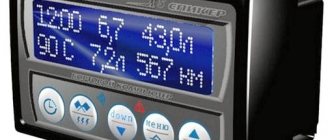
The need for replacement, as a rule, arises in the event of malfunctions in the operation of the device. If the computer begins to show incorrect data, the cause of the problem may lie in the contacts. Usually the contacts come off as a result of off-road driving and frequent vibrations. In this case, the problem can be resolved by reconnecting the devices.
In some cases, incorrect data is caused by glitches. If this is the case, then you won’t be able to solve the problem on your own - only specialists with the necessary equipment can help. In practice, the bookmaker can be reflashed, that is, the software can be reinstalled. In the event that the demonstration of incorrect parameters is associated with damage to the electronics, then the only correct solution is to replace the BC. Usually in this case, if there is mechanical damage to the system elements, the on-board computer does not work, which is the reason for its replacement (the author of the video is the IZO)))LENTA channel).
About the BSK-4 block diagram
On many forums, owners of dump trucks and MAZ trucks often ask to see a photo of the BSK 4 diagram.
However, this diagram is not included in vehicle operating manuals.
Usually it is necessary to repair the unit.
The process of troubleshooting and resoldering parts is extremely complex.
The fact is that even a professional is difficult to replace all the components with a guarantee of further work.
Therefore, if your BSK-4 unit is broken, we advise you to buy a new one. Repairing a spare part is extremely dangerous.
Basic principles
Regardless of the type of engine used, the basis of the wiring used in the VAZ 2110 car is the same. It's easy to find a diagram, but not so easy to understand.
Let's look at the basic principles of wiring.
- All equipment and devices powered by electricity in the VAZ 2110 are based on a single-wire connection. VAZ designers specially provided for wires of certain colors to each be responsible for their own functions. Therefore, certain equipment is connected using wires of their own color. This allows you to independently understand the wiring, make it easier to carry out repair work and not spend money on car repair services.
- The downside to the VAZ 2110 is that the mass is the car body itself.
- The positive wire of the batteries on the top ten always comes only in red. Therefore, when making repairs, try not to change the color of the wire, so as not to confuse yourself.
- For each system that is connected to the electrical system, it is equipped with its own separate wiring harness.
- The VAZ 2110 is designed in such a way that when the battery is turned on, all electrics and electrical equipment are energized. This is related to the most common recommendation, which you have seen more than once in our materials, where we described the repair or replacement of certain components - disconnecting the negative terminal from the battery.
- Do not forget about the existence of the so-called contactless system. This system is required to create a high-quality spark, which is simply necessary to ensure combustion of the air-fuel mixture. In order for a contactless system to function, high voltages are indispensable.
Carburetor models
The first versions of the VAZ 2110 model, which the domestic plant began to produce, were equipped exclusively with carburetor engines. Only after some time more modern injection versions appeared. They are objectively better. But this does not take away the fact that many have dozens of them under the hood with a carburetor.
Are there any significant differences in terms of electrical circuitry between a carburetor and an injector? We can say no. The carburetor systems used are almost entirely the same as on the more modern version.
Part of interior wiring
Also, you will not encounter serious problems in the form of electrical wiring if you suddenly want to replace a carburetor engine with an injection engine or equip the car with additional electrical equipment. You will even find identical plugs in the engine compartment.
The only nuance of switching from a carurator to an injector is the need to install additional wiring from the fuel pump to the on-board computer.
Injector
In addition to the wiring, which is identical for the carburetor and injector, the latter is additionally equipped with fuses and sensors.
In practice, due to the large number of regulators that ensure the operation of an electronic engine control unit of an injection type with 8 or 16 valves (there is none on the carburetor), the system turns out to be more complex. To repair it, you need to carefully understand all the components and their location.
Electrical diagram
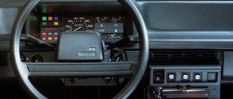
General diagram of devices
If you look from the back of the instrument panel, here it is in sequence - from top to left to right:
- Fuel level indicator;
- Combination of instrument lighting lamps;
- Right turn control;
- Left turn control;
- Tachometer;
- Next is the block, there are a lot of plugs in it;
- And the top part of the dashboard is completed by an antifreeze temperature indicator.
VAZ 2110 dashboard connection diagram
The lower part of the dashboard (also from left to right and from the back of the dashboard). The following part of the instruments is located here:
- high beam controller (bulb);
- alarm controller;
- brake fluid level control lamp;
- speedometer;
- CHECK ENGINE controller;
- battery charge control;
- parking brake controller;
- oil pressure controller;
- air damper controller in the carburetor;
- outdoor lighting controller.
White block
The connector number, wire color and the unit (assembly) to which it goes are located in the white block as follows:
- The first connector has a black wire. Its purpose is the body (mass);
- In the second - red-brown - this is a low-voltage supply from the electronic control unit - tachometer;
- The third, yellow one is also a tachometer, but this is a high-voltage supply from a coil;
- The fourth, red-blue is Const from the battery + 12V, going through the sixth fuse;
- The fifth, green-white - it is intended to indicate the coolant temperature;
- Sixth, green-yellow – for size fuse F1;
- The seventh connector does not have its own color and goes to the “choke”, the throttle valve;
- Eighth, red and white - CHECK ENGINE light;
- In the ninth and tenth there are 2 orange wires each, leading to 2 power fuses F19+12V;
- In the eleventh there are 2 blue-brown wires leading to the “BK” terminal of the parking brake;
- The twelfth, brown-white is the output “D” of the generator;
- Thirteenth, gray and blue – for the oil pressure sensor.
White block (X1) and Red block (X2) of the VAZ 2110 instrument panel
Red block
The number is the connector according to the account, followed by the color of the wire and an indication of the device to which it goes in the red block of the VAZ 2110:
- Blue and red go to the sensor showing the external temperature;
- Orange - power fuse F19+12V;
- Black, 2 wires – ground, body;
- White - light switch for all devices;
- Blue - right direction indicator;
- Blue and black - left turn signal;
- Blue with pink - TJ level;
- Brown – leading to the trip computer;
- Gray - speed indicator;
- Pink - Fuel gauge (terminal “T”);
- 2 black-green wires - high beam fuse (F3);
- Blue and white - emergency light switch;
- White - leading to the ignition switch (terminal 50).
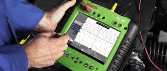
Diagnostics using a scanner
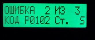
The method involves connecting an external computer with the program installed. This opens up more opportunities for car diagnostics. In this case, error codes for VAZ 2110 and VAZ 2112 consist of 5 characters.
- P – failure or malfunction of the power plant, transmission;
- B – body systems are damaged;
- C – a problem has been detected in the vehicle’s chassis;
- U – violation of pairing of different modules.
- 0 – general value;
- 1/2 – manufacturer code;
- 3 – reserve.
- 1-2 – violation in the air-fuel mixture supply devices;
- 3 – malfunction of the ignition units;
- 4 – atmospheric emissions control device;
- 5 – malfunction of the engine speed or engine speed meters;
- 6 – failures in electronics;
- 7-8 – malfunction of the gearbox module;
- 9-0 – reserve unit.
The last two digits give the serial number of the breakdown and its location.
Ignition and engine control circuit
Here are the control diagrams for the following internal combustion engines:
- 21120 – January 5.1 or BOSCH M1.5.4N, Euro-2;
| Motor | 21120 (Euro-2) | 21124 (Euro-2) | 21124 (Euro-3) |
| Injectors | 1 | 2 | 2 |
| Ignition coil | — | 1 | 1 |
| Candles | 2 | — | — |
| Ignition module | 3 | — | — |
| Diagnostic connector | 4 | B | B |
| ECU | 5 | 3 | 3 |
| Tidy taps | 6 | E | E |
| Ignition relay (6) | 7 | 4 | 4 |
| Ignition fuse (1) | 8 | 5 | 5 |
| Fan relay (4) | 9 | 6 | 6 |
| Fan fuse (2) | 10 | 7 | 7 |
| Fuel pump relay (5) | 11 | 8 | 8 |
| Fuel pump fuse (3) | 12 | 9 | 9 |
| Mass air flow sensor | 13 | 10 | 10 |
| Rough road sensor | — | — | 11 |
| TPDZ | 14 | 11 | 12 |
| DTOZH | 15 | 12 | 13 |
| RXX | 16 | 17 | 14 |
| Lambda probe main | 17 | 14 | 15 |
| Additional lambda probe | — | — | 16 |
| Knock sensor | 18 | 15 | 18 |
| DPKV | 19 | 16 | 19 |
| Canister purge valve | 20 | 13 | 17 |
| APS block | 21 | 18 | 20 |
| APS indicator | 22 | 19 | 21 |
| Speed sensor | 23 | 21 | 23 |
| Fuel pump + level sensor | 24 | 22 | 24 |
| Oil pressure sensor | 25 | 23 | 25 |
| Antifreeze thermometer sensor | 26 | 24 | 26 |
| Oil level sensor | 27 | — | — |
| Phase sensor | 28 | 20 | 22 |
| ABS connector | A | A | A |
| Air conditioner connector | B | IN | IN |
| Fan connector | C | — | — |
| Illumination of the ignition switch (to the blue-white wire) | D+E | — | — |
| Bends to the door harness | — | D | D |
| + battery | F | G | G |
| Weight | G1+G2 | G1+G2 | G1+G2 |
The elements installed in the additional mounting block are indicated in brackets.
Mounting block on the right side under the dashboard
Correct operation
With the right approach, the installed BC will not cause problems.
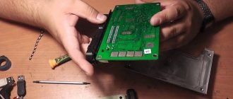
However, if it shows unreliable information, then it is worth removing the on-board computer and checking it for serviceability. How to remove the device is clear. After all, it has a disconnectable connector, so you need to dismantle it in the reverse order. The main thing to remember is that this is a fragile thing and can be broken. After dismantling, you should check the integrity of the soldering and wires and eliminate any breaks . Afterwards, put the device where it was before and use the working device again.
vote
Article rating