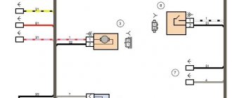
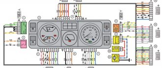
Electrical diagram of instruments on the panel
In the VAZ 2109, electrical circuits are placed using a printed circuit board on a board, which is secured by springs with latches on the rear wall of the panel housing. Three groups of plugs can be divided into:
- BSK;
- lighting, dimensions;
- characteristics of the nodes.
The conditional numbering of the nests differs from the standard arrangement. The top plug is numbered 1, then the numbering continues down the right side, and the numbers continue at the top along the left side. BSK terminals have a horizontal position and are numbered from left to right, 2-5 top row, 6-9 bottom.
In instrument circuits with the European version of the torpedo and high, the connector blocks are located horizontally. If you look from the trunk, there are 13 lighting sockets at the top of the BSK, on the right, and operating indicators of the units on the left.
On-board control system
BSK was created on cars with a high modification of the torpedo and the Euro version. Helps monitor the condition of the brake pads and fluid levels in the components while driving. Level sensors are displayed on the panel:
- brake fluid;
- oils;
- coolant;
- washing.
In addition, there is a relay for monitoring the operating condition of the lamps and a sensor indicating the degree of wear of the linings on the brake pads. In normal condition, the indicators do not light up and do not attract attention.
All BSK lights come on when the ignition is turned on for a few seconds and go out. During movement, they begin to glow when the controlled element approaches a critical level, or rather the minimum level for the normal operation of a particular unit. Measures must be taken immediately, since there is no reserve for the signal from the dashboard lamp.
The on-board control system greatly simplifies vehicle maintenance, especially on long routes, and warns of a critical situation. But it does not exclude the need to check oil and brake fluid levels before leaving the garage, regular brake maintenance and changing the linings before they wear out.
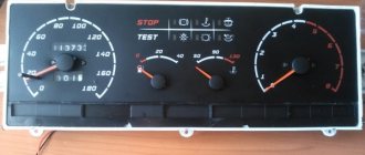
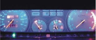
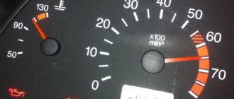
Main indicators
The VAZ 2109 has an instrument panel, an electrical circuit on the board, and has different color connectors for the output plugs. Sensors that are most important for safe movement and normal operation of the car are connected to red. These are indicators such as:
- fuel level in the tank;
- parking brake condition;
- carburetor choke position;
- emergency pressure in the system;
- battery charge level;
- fuel injection;
- tachometer.
The right turn indicator lamp and resistors are also connected to this group of connectors. In older models before 1995, VAZ 2109, the electrical circuit does not have BSK connectors, so the distribution of lamps is somewhat different and includes some lamps for emergency and control lights, brake fluid level and hazard warning lights.
Lighting fixtures and dimensions
The white connector of the output plugs is connected mainly to sensors that signal the operation of lighting devices, these are lamps:
- outdoor lighting;
- fog lights;
- dimensions;
- emergency lighting;
- high beam;
- turning indicators;
- stops;
- reverse speed headlights;
- heated rear window.
This group of sockets also includes the connection of such indicators as seat belts not fastened and injection toxicity adjustment, indicators for turning left turns on at the moment of starting to move.
Relay and fuse box diagram 2109
The fuse blocks do not depend on the fuel injection system used - carburetor or injector. BP will differ only by year of manufacture of the car. That is, the mounting blocks for the carburetor and injector are the same. The VAZ 2109-099 fuse box (carburetor, injector) is located under the hood, in the compartment in front of the windshield on the left side.
Fuse block 2114-3722010-18
K1-relay for turning on headlight cleaners; K2-relay-breaker for direction indicators and hazard warning lights; K3 - windshield wiper relay; K4-relay for monitoring the health of lamps; K5-power window relay; K6 - relay for turning on sound signals; K7-relay for turning on the electric heating of the rear window; K8-relay for high beam headlights; K9-relay for low beam headlights; F1-F16 - fuses.
Fuse block 2114-3722010-60
K1 - Headlight wiper relay, K2 - Turn signal and hazard warning relay, K3 - Windshield wiper relay, K4 - Brake light and parking light relay, K5 - Power window relay, K6 - Horn relay , K7 - Rear window heating relay, K8 - Headlight high beam relay, K9 - Headlight low beam relay, F1 - F16 - Fuses, F1 - F20 - Spare fuses.
Attention! The power terminals on the generator often become loose, heat up, spark and melt the wiring. Pay attention to this point when searching for possible faults yourself.
Source
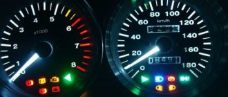
Travel speed
The speedometer is one of the most important indicators. In addition to the speed of movement, it also shows the distance traveled. On models produced before 1995, this is mainly only the total mileage value. Later models have a daily trip counter and a button that allows you to reset it.
If malfunctions occur in the speedometer, you should check the fastenings and condition of the flexible shaft. Pay attention to bends, the radius of which should be more than 10 mm. Replace the drive cable; if this does not help, then installing a new speedometer is required. The price of services in the salon for this repair is small, so it is better to immediately contact specialists.
Pinout of the dashboard of VAZ2113, 2114, 2115
There are 26 contacts on the VAZ-2114 instrument panel, each of which is responsible for the operation of the indicators of this panel. If a plus is supplied to the panel, then each contact displays information about the state in which the car is currently located.
White block (X1)
Red block (X2)
- Housing (weight) - black
- To ambient temperature sensor - cyan-magenta
- Tachometer (low voltage input from ECU) - brown/purple
- Fuse F16 (to terminal 15 of the ignition switch) - orange
- Tachometer (high voltage input from coil) - yellow
- Housing (weight) - black
- To fuse F3 of the mounting block (+battery) - white-purple
- Instrument lighting control - white
- Coolant temperature sensor. - green-white
- Turn signal RIGHT - blue
- To fuse F10 of the mounting block - brown
- Turn signal LEFT - blue-black
- Brake fluid level - pink-blue
- Check Engine Light to ECU Controller - White-Purple
- To the trip computer - brown
- To the ECU controller - pink and black
- Speed sensor - gray and yellow
- To the fuel gauge sensor - orange
- To the fuel gauge sensor - pink
- To the parking brake switch - brown-blue
- Fuse F14 of the mounting block - green-black
- Alternator terminal "D" through fuse panel - brown and white
- Hazard switch
- Oil pressure sensor - blue
- To terminal “50” of the ignition switch - purple
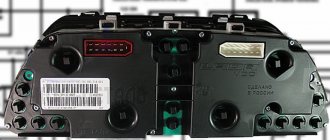
In addition, special indicators and signal sensors are installed on the instrument panel, and the panel itself is controlled by a special electronic unit. Having disassembled the instrument panel, you can see that there are two pads inside it: red and white. And all inputs, outputs and fuses are connected to the plug. If the sensors fail, they will need to be replaced. It is also better to replace damaged or oxidized wires. Indicator lights, like any other, sometimes burn out. Undoubtedly, they need to be replaced with whole ones. Along with them, the lamp sensor often burns out.
Electrical circuit repair
The VAZ 2109 power supply circuit is based on general connection principles. Plus goes from the battery to all devices. The minus for each is indicated separately, from the unit whose operation is signaled by a specific light bulb. Most breakdowns can be fixed with your own hands.
Any video will tell you that if several indicators fail to work, you should start by checking the serviceability of the fuses. Having opened the hood, you will see on the right under it a black box with a diagram of the location of each specific breaker. Select the correct fuse and replace.
Before starting repairs, remember that the instructions for working with electrical circuits, regardless of voltage and current, require turning off the power and discharging the existing capacitors. You shouldn't risk your health. Moreover, you can accidentally short the contacts and completely burn the entire board.
If the control lamps fail, check the fastening in the sockets, clean the contacts and tighten them, which oxidize over time, replace the lamps. Use a tester to make sure there is no broken wire.
Most often, malfunctions occur in the operation of fuel level readings. You should check the setting of the float, which may be knocked down, and the resistor winding responsible for the deflection of the needle. To do this, you need to dismantle the sensor, ring the circuit, making sure it is in good condition and integrity. Then adjust the limiter. All this is done after checking the suitability of the fuses.
If the fuel level indicator arrow constantly changes its position abruptly, the contact between the current collector and the resistor has weakened. In this case, it is best to replace the sensor itself, since correcting this deviation will not be effective.
Pinout of the dashboard VAZ2108, 2109, 21099
Connection diagram of the instrument cluster before 1996.
1 — relay-interrupter for the parking brake warning lamp; 2 — tachometer with voltage stabilizer; 3 — instrument cluster lighting lamp; 4 — temperature indicator; 5 — BSK control unit; 6 — fuel level indicator; 7 - resistor 50 Ohm, 5 W; 8 — “CHECK ENGINE” control lamp for the toxicity reduction system; 9 — control lamp for high beam headlights; 10 — side light indicator lamp; 11 — backup warning lamp; 12 - warning lamp for unfastened seat belts; 13 — control lamp for left direction indicators; 14 - resistor 470 Ohm, 0.25 W; 15 - electronic voltmeter; 16 — control lamp for right direction indicators; 17 — warning lamp for emergency oil pressure; 18 — fuel reserve warning lamp; 19 — control lamp for the carburetor air damper; 20 — “CHECK ENGINE” warning lamp for the fuel injection system; 21 - parking brake warning lamp.
Instrument cluster wiring diagram after 1996
1 — tachometer; 2 — instrument cluster lighting lamp; 3 — temperature indicator; 4 — BSK control unit; 5 — fuel level indicator; 6 — “CHECK ENGINE” warning lamp for the toxicity reduction system; 7 — control lamp for high beam headlights; 8 — side light indicator lamp; 9 — backup warning lamp; 10 - warning lamp for unfastened seat belts; 11 — control lamp for left direction indicators; 12 — battery charge indicator lamp; 13 — control lamp for right direction indicators; 14 — warning lamp for emergency oil pressure; 15 — fuel reserve warning lamp; 16 — control lamp for the carburetor air damper; 17 — “CHECK ENGINE” warning lamp for the fuel injection system; 18 — parking brake warning lamp; B1 - 91 kOhm resistor; B2 - resistor 50 Ohm, 5 W.
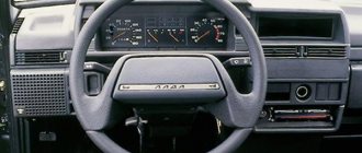
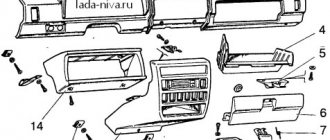
High instrument panel
According to the diagram presented below, the VAZ 2109 with a high panel has the following components.
High dashboard
Item number
What is this
Hazard switch
Windshield wiper and washer control lever
Central nozzles of the interior heating and ventilation system
On-board computer (not available on all trim levels)
Glove compartment lid (glove compartment)
Side nozzles of the interior heating and ventilation system
Speaker (loudspeaker) trim
Power window switches (available on certain trim levels)
Control panel for heating and interior ventilation system
Gearbox shift lever
Hand brake lever
Carburetor choke handle
Horn switch (horn)
Instrument panel light switch
Front seat heating switch (available as standard)
Rear fog light switch
Front fog lamp switch (not available on all trim levels)
Rear defogger switch
Hood lock drive lever
Turn signal and light control lever
Outdoor optics switch
Panel tuning options
If you decide to customize your toolbar, you'll likely be wondering what options exist for launching it. The tuning damper is known to please the driver's eye, so this problem is relevant for many car owners.
Dismantling the shield
To fine-tune the dashboard, you must first delete the order itself.
To do this, you just need to disconnect eight fasteners; you can use a regular knife for this:
- First, the fastenings on the driver's side are disconnected;
- then you need to unlock the latches located there, at the top;
- after this you can disable the central part of the order;
- the panel itself has been dismantled (video by Artem Volivach).
Improvement and replacement of backlight
To adjust the backlight on a VAZ 2109, the light sources must be replaced after removal; it is advisable to use diode bulbs, and if necessary, you can change the scale itself.
The setup procedure includes the following steps:
- First, disassemble the standard insert in which the ladder is located. Remove all the arrows and set them aside, then drill the corresponding holes in the new covers. To prevent the arrows from sticking together during operation of the devices, the holes can be widened.
- Next, you need to remove all the standard light sources - just disassemble the entire circuit and install diode devices instead of the old light bulbs. When installing new sources, observe the polarity, because if it is reversed, this will lead to the inoperability of the device as a whole.
- When the lamps are installed, you can begin finishing the stairs. Take new blocks and use fluorescent paint or a marker to draw numbers on the scale. Such a marker or paint will be needed to make the numbers shine brighter and stand out under the LED backlight of the dashboard.
- After completing the backlight adjustment, you will need to carefully install the circuit and install new overlays on top of it. During installation, be careful not to damage the screen elements.
Removal
Having familiarized themselves with the diagram of the high instrument panel of the VAZ 2109, many will probably think about the issue of removing it.
There are more than enough reasons to dismantle the panel:
- Repair, modernization of the heating system;
- Body repair;
- Replacing the old panel with a new one;
- Car painting;
- Body sound insulation, etc.
Dismantling process
This is not to say that removing the panel is a difficult process. The main problem is the time that needs to be spent on the work. The task requires concentration and increased attention in order to dismantle all elements, devices, and linings.
The process looks like this.
- Remove the steering wheel itself, otherwise it will seriously interfere with you when dismantling the panel.
- Pull the carburetor choke towards you. Injection engines do not have such an element. Then remove the plastic handle from the drive rod.
- Next, the decorative trim of the console is removed. To do this, simply unscrew the two mounting screws on the sides.
- Dismantle the ashtray and remove the cigarette lighter from its seat.
- Remove the handle that controls the speed of the fan motor.
- Using a screwdriver, pry the levers of the interior heater drive, which will allow you to remove these decorative elements.
- Disconnect the block with wires from the heater fan mode switch.
- Remove the two power wires for the backlight of the stove control panel from the contacts.
- Now you will need to get rid of several decorative control knobs - headlight hydraulic adjustment, instrument lighting control.
- The next step is to dismantle the hydraulic corrector itself and the lighting regulator. You will need a socket wrench that matches the diameter of the mounting nuts you are using. After unscrewing, push them inside. A little later you will be able to take them out.
- The air deflectors for heating the side windows are removed on the left and right.
- Here, using a Phillips screwdriver, you need to unscrew one mounting screw on each side that holds the upper panel covers.
- Remove the exterior light switch from the dashboard. To do this, you need to carefully pry the switch with a flat screwdriver and pull it out. Do not pull too hard as the switch is limited by the length of the wires used. Disconnect the power supply with the wires from the switch and set it aside. The block can still be pushed inside the panel.
- If you have an audio system, remove the radio. Now remove the standard socket from the radio. Of course, if you still have it.
- Unscrew the central fastener from the panel trim.
- Let's start by removing the dashboard trim. Before doing this, be sure to unlatch the latches located under the dashboard. This is done with a pair of flathead screwdrivers. Insert the tools along the edges and press down. By performing upward movements, the panel rises and then is completely removed.
- The cover has been removed, but that's only half the battle. Next, you can easily disconnect the power supply from the cigarette lighter and the cigarette lighter lamp.
- Also, without much difficulty, the wires from the alarm signal and the hazard warning lights are disconnected.
- Be sure to remember to remove the decorative trim from the front speaker and the heated glass switch, plus the rear fog light switch trim. If you also have a speaker, you will need to remove it.
- Reach through the hole under the speaker to disconnect the wiring harness from the fog light and rear window defroster switch.
- The instrument cluster is held on the panel by two mounting screws, which must be unscrewed. Pull it towards you, unscrew the nut and remove the flexible drive cable from the speedometer.
- That's it, the block with wiring from the instrument cluster can be disconnected and put aside for now.
- Do the same with the ignition switch - disconnect the block with wires, remove the ignition relay ground wire from the connector.
- Here, in close proximity, you will see a wire from the air damper warning lamp. But only for the carburetor VAZ 2109. Injection versions are not equipped with this wire.
- On each side of the panel, unscrew one bottom mounting screw.
- Disconnect the power supply wiring for the glove compartment lighting.
- Unscrew the heater panel fasteners and move it down. This way the panel will not disturb you.
- Remove the fasteners for the interior heater guide rod.
- Unscrew all the remaining side top and center fasteners, after which the panel can finally be completely removed.
One of many screws
Your further actions directly depend on the reasons why you decided to go through this difficult path of dismantling the dashboard.
Removing the panel, as you can see, is not a difficult process, but it is troublesome. Lots of parts, elements, fasteners. The most important thing here is to strictly adhere to the instructions and not to forget that dismantling is only half the way. Some people encounter problems during the reassembly process.
Pinout of the dashboard of VAZ2105, 2106, 2107
Old panel (with oil pressure gauge)
In addition to the presence of an oil pressure indicator, it is worth noting that this instrument panel does not have an air damper indicator lamp (choke), and the emergency oil pressure lamp is located next to the pressure indicator. Because of this, it contains lamps for low brake fluid levels and fog lamps.
White 6-terminal block X1:
- Gasoline level sensor
- Turn signal indicator lamp
- Battery charge sensor (voltmeter -)
- Gasoline level warning lamp
- Overall plus (+)
- Battery charge sensor (voltmeter +)
White 8 terminal block X2:
- Fog lamp warning lamp
- High beam warning lamp
- Dimensions indicator lamp
- Empty
- Battery charge indicator lamp
- Brake fluid level warning lamp
- Empty
- Parking brake warning lamp
Orange 6-terminal block X3:
- General minus (-)
- Tachometer VAZ
- Instrument lighting
- Oil pressure sensor
- Oil pressure warning lamp
- Coolant temperature sensor
New instrument panel (with econometer)
Here, everything is the other way around - there is no oil pressure indicator (instead there is an econometer), instead of a brake fluid level lamp there is a suction lamp (or an engine management system lamp on injectors), and instead of a fog lamp lamp there is an oil pressure lamp.
White 6-terminal block X1:
- Gasoline level sensor
- Turn signal indicator lamp
- Battery charge sensor (voltmeter -)
- Gasoline level warning lamp
- Overall plus (+)
- Battery charge sensor (voltmeter +)
White 8 terminal block X2:
- Dimensions indicator lamp
- High beam warning lamp
- Oil pressure warning lamp
- Empty, but there is a terminal in the wiring that goes to the brake fluid level sensor
- Battery charge indicator lamp
- Indicator lamp for the air damper (choke) or engine control unit for injectors
- Empty
- Parking brake warning lamp (handbrake)
Orange 6-terminal block X3:
- General minus (-)
- Tachometer (if this contact is empty, then the tachometer is on pin #4)
- Instrument lighting
- Empty, and if not empty - to the tachometer
- Empty
- Coolant temperature sensor
Second connection diagram option
Full scheme
1 – block headlight; 2 – gear motor for headlight cleaner*; 3 – engine compartment lamp switch; 4 – sound signal; 5 – electric motor of the engine cooling system fan; 6 – fan motor activation sensor; 7 – generator; 8 – solenoid valve for turning on the headlight washers*; 9 – solenoid valve for turning on the rear window washer* (not installed on the VAZ-21099); 10 – solenoid valve for turning on the windshield washer; 11 – electric motor for glass washer; 12 – oil pressure warning lamp sensor; 13 – carburetor solenoid valve; 14 – carburetor limit switch; 15 – spark plugs; 16 – plug socket for a portable lamp; 17 – engine compartment lamp; 18 – ignition distributor sensor; 19 – carburetor solenoid valve control unit; 20 – windshield wiper gearmotor; 21 – switch; 22 – ignition coil; 23 – starter; 24 – top dead center sensor of the 1st cylinder**; 25 – diagnostic block**; 26 – starter activation relay; 27 – coolant temperature indicator sensor; 28 – reverse light switch; 29 – battery; 30 – brake fluid level sensor; 31 – mounting block; 32 – parking brake warning lamp switch; 33 – brake light switch; 34 – glove box lighting lamp; 35 – heater fan electric motor; 36 – additional resistor of the heater electric motor; 37 – heater fan switch; 38 – backlight lamp for heater levers; 39 – cigarette lighter; 40 – rear window heating switch; 41 – rear fog light switch; 42 – fog light circuit fuse; 43 – alarm switch; 44 – external lighting switch; 45 – ignition relay; 46 – ignition switch; 47 – steering column switch; 48 – instrument lighting switch; 49 – side direction indicator; 50 – lamp switch on the front door pillar; 51 – lamp switch on the rear door pillar (not installed on VAZ-2108 and VAZ-21083); 52 – lampshade; 53 – sockets for connecting individual interior lighting to the lampshade; 54 – switch for the carburetor air damper warning lamp; 55 – turn signal indicator lamp; 56 – indicator lamp for external lighting; 57 – rear fog light indicator lamp; 58 – backup warning lamp; 59 – control lamp for high beam headlights; 60 – indicator lamp for heated rear window; 61 – speedometer; 62 – instrument cluster; 63 – instrument cluster lighting lamps; 64 – coolant temperature indicator; 65 – voltmeter; 66 – fuel level indicator with reserve indicator lamp; 67 – econometrician; 68 – “STOP” indicator lamp; 69 – battery charge indicator lamp; 70 – control lamp for the carburetor air damper; 71 – hazard warning lamp; 72 – brake fluid level warning lamp; 73 – parking brake warning lamp; 74 – oil pressure warning lamp; 75 – rear light; 76 – sensor for level indicator and fuel reserve; 77 – pads for connecting to the rear window heating element; 78 – license plate lights; 79 – rear window wiper gear motor* (not installed on VAZ-21099)
The order of conditional numbering of plugs in blocks:
a – mounting block, instrument cluster, ignition switch and windshield wiper (for blocks with a different number of plugs, the numbering order is similar); b – ignition distributor sensor; c – switch and carburetor solenoid valve control unit; d – headlight units, headlight and rear window cleaners; g – interior lighting lamp; e – fuel level sensor; d – rear lights (pin numbering in order from top to bottom)
* Installed on parts of manufactured cars. ** Not installed since 1995.
Hello everyone, I have already agreed with Ritchi, at the end of the week they will send me a standard shield 2109.
Now let’s remember important things)
Pinout of connectors of the VAZ 2109 instrument cluster with on-board control system
Plug number - Address (purpose) of the plug
1 - Reserve output; 2 - Reserve output; 3 - To the seat belt relay; 4 - Fuse “5” for device protection (“+” for a voltmeter); 5 - To terminal “49aL” of the turn signal and hazard warning relay; 6 — —————–; 7 — —————–; 8 - To fuse “7” for protecting internal and external lighting lamps; 9 - To fuse “14” for high beam protection of the left headlight; 10 - Reserve output; 11 — To the fuel level sensor (output for the fuel level indicator); 12 - To terminal “61” of the generator; 13 - To the temperature indicator sensor.
1- —————– 2 — Fuse “5” for device protection (“+” for powering devices); 3 - To terminal “K” of the ignition coil; 4 - To the instrument lighting switch; 5 - To the fuel injection system control unit; 6 — —————–; 7 - To ground; 8 - To the parking brake switch; 9 - Reserve output; 10 - To the carburetor air damper warning lamp switch; 11 — To the fuel level sensor (output for the fuel reserve warning lamp); 12 - To the oil pressure warning lamp sensor; 13 - To terminal “49aR” of the turn signal and hazard warning relay interrupter.
BSK - 9-terminal connector:
1 — Fuse “5” for device protection (“+” power supply); 2 - To terminal “50” of the ignition switch; 3 - To ground; 4 - To the washer fluid level sensor; 5 - To the oil level sensor; 6 - To the coolant level sensor; 7 - To the brake fluid level sensor; 8 - To brake lining wear sensors; 9 - To terminal “3” of the lamp health monitoring relay.
Instrument panel wires for VAZ 21083, 21093, 21099 cars with a “high dashboard” after 1998. Fuse and relay mounting block 2114-3722010-60.
Diagram of connecting wires to connecting blocks
More articles on electrical VAZ 2108, 2109, 21099
Modifications of VAZ-2109
VAZ-2109 . The basic model, which was produced from 1987 to 1997, was equipped with a 1.3-liter VAZ-2108 carburetor engine with a capacity of 64 horsepower.
VAZ-21091 . Modification of a car with a derated VAZ-21081 engine, 1.1 liter and 54 horsepower. It was mass-produced from 1987 to 1997.
VAZ-21093 . Modification of a car with a VAZ-21083 carburetor engine, 1.5 liters and 73.4 horsepower. Serially produced from 1988 to 2006.
VAZ-21093i . Modification with a VAZ-2111-80 injection engine, 1.5 liters. the first prototype appeared in 1994, mass production began in November 1998.
VAZ 21093-22 . Model made specifically for the Finnish market. It features improved interior trim, pre-installed alloy wheels and a new dashboard. The car was equipped with a 1.5 liter injection engine. Produced from 1995 to 1998.
VAZ-210934 . An all-wheel drive SUV with a VAZ-21093 body placed on a Niva frame, on which the suspension, steering, engine, gearbox and transfer case from the same VAZ-2121 Niva model were already installed.
VAZ 2109-90 . A variant of the car, which was equipped with a compact two-section Wankel rotary piston engine with a volume of 654 cm3.
VAZ-21096 . Export modification of the VAZ-2109 for countries with left-hand traffic, the steering column was located on the right.
VAZ 21097 . Export modification of VAZ 21091 with right-hand drive.
VAZ 21098 . Another export modification, but this time the VAZ 21093 model with a right-hand steering column.
VAZ-2109 Carlota . A car produced from 1991 to 1996 in Belgium by Scaldia-Volga.
VAZ-21099 . The next independent car model, which is a modification of the “nine”. This car had a 4-door, 5-seater sedan body and a rear overhang extended by 200 mm.
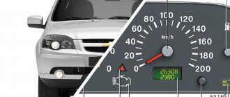
VDO instrument panel
Glowing VDO instrument panel from VAZ 2110
I missed the Latvian illuminated instrument cluster (CI) - I didn’t buy it in the summer of 1999, when it cost 600 rubles. And now the situation with them is quite tense, or more precisely, “... there is no delivery and is not expected.” They say that they are in Tolyatti, but for $80 with a speed sensor. Expensive…
However, in markets and stores there is an abundance of VDO instrument clusters for the VAZ 2110 car, model 2110-3801010-02, which is also installed on the 115 VAZ model. In relation to the “eighth” panel, it has disadvantages:
- Doesn’t fit very well; you’ll have to cut the torpedo visor, otherwise some of the lamps will not be completely visible;
- There is no built-in BSK (on-board control system);
- It is necessary to select a fuel level sensor with the appropriate resistance, otherwise the indicator may be “slightly misaligned”.
Otherwise there are only advantages
- All instruments are more accurate, especially noticeable in the fuel level and coolant temperature sensors;
- The speedometer and tachometer are located in the center, all arrows are controlled by stepper motors - the movement of the arrows is smooth;
- The fuel light doesn't blink like crazy, because... it is ignited by electronics, and not by a contact in the tank;
- The total and daily mileage are displayed on the LCD display - when the car is not started, the mileage is not visible on the instrument panel. Relevant for new cars.
- There is a self-diagnosis mode - you need to turn on the ignition while pressing the reset button for the daily mileage counter.
Another plus: the speedometer cable becomes unnecessary, which often makes various sounds - sometimes it clicks, sometimes it clicks... True, I also had to buy a DS (speed sensor, since I have a carburetor car). The sensor needs to be taken only with an iron pin and a connector identical to the connector of the Hall sensor - it is easier and much cheaper to buy a chip for it.
Connection
Three chips fit the standard CP: white (X1) and red (X2), also one smaller red one (for BSK). Before changing the wires, a bundle of wires from the red block was pulled through the window in the dashboard next to the wires of the white block. Otherwise, you won’t be able to remove the dashboard later—tangled wires won’t allow it.
Equipment diagram for VAZ-2109 injector
The VAZ 2109 wiring for the injector has many connectors for connecting sensors to the computer.
- TPS (throttle position sensor);
- DPKV (crankshaft position sensor);
- DT (temperature sensor);
- DSA (vehicle speed sensor);
- Canister purge valve;
- MAF (mass air flow sensor);
- DD (knock sensor) and others.
The weak point of the harnesses is the power wiring on the bottom shelf of the radiator, which is constantly exposed to high temperatures and in this place it is in no way protected from water and dirt. Another problem is a harness under the carpet next to the driver's seat. Moisture constantly accumulates there, and in order to remove it, you need to dry the floor, inevitably tugging on the rope.
Since the mid-90s, VAZ 2109 began to use engines with an injection system, which greatly changed the electrical layout of the engine compartment and instrument panel. Below is an electrical diagram of a 1999 car with an ECM type GM ISFI-2S and January 4/4.1.
- 1 - nozzle system;
- 2 - candles;
- 3 — ignition control module;
- 4 — diagnostic connector;
- 5 — General Motors or January controller;
- 6 — connector for connecting the instrument cluster;
- 7 — main relay of the system;
- 8 — fuse for power supply wiring of the controller and ignition system module;
- 9 — protection of the speed sensor and air flow meter circuits;
- 10 — fuel supply pump power protection;
- 11 — fuel pump controller;
- 12 — engine temperature meter;
- 13 — idle system;
- 14 — detonation meter;
- 15 — tank purge system for collecting fuel vapors;
- 16 — crankshaft position meter;
- 17 — speed meter;
- 18 — air flow meter;
- 19 — lambda probe;
- 20 — throttle position angle meter;
- 21 — electric fuel pump complete with fuel level sensor;
- 22 — connection of the ignition system;
- 23 — control lamp;
- 24 — ignition switch;
- 25 - switching block;
- 26 — radiator cooling fan.
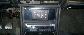
On-board computer for VAZ 21099 injector
Many owners of VAZ 21099 cars with an injector want to install an on-board computer (BC) on their cars. This desire is understandable, because such a device not only provides information on fuel consumption, ground speed, mileage and crankshaft speed, but also carries out real-time diagnostics of important vehicle systems.
This, in turn, makes it possible to identify engine, electronics and attachment faults as soon as they occur. This greatly simplifies the life of car enthusiasts, as it becomes possible to predict serious car breakdowns and virtually eliminate unplanned car repairs. You can install an on-board computer on a VAZ 2108-99 without the help of specialists. To do this, you need to have a little knowledge of electrical engineering and some free time.
Return to contents
Selecting an on-board computer
There are a lot of electronic devices on the market that supposedly can be installed on cars of the Lada Samara family. They are produced in different countries, are in different price segments and differ in many respects. Don't pay attention to sellers' advice.
First of all, the on-board computer of the VAZ 21099 must be compatible with the protocols of the electronic control unit (ECU) installed on your car. Therefore, find out in advance which ECU you have, and then go get the computer. When choosing an on-board computer for the VAZ Sputnik - Samara, pay attention to the following parameters.
Among the brands of on-board computers on the market, experts recommend devices from the “Stat” and “Multitronics” brands. They are guaranteed to fit Lada cars. The choice of device model depends on the car model and the budget of the car owner.
Prices range from 1,500 rubles for a device without a voice synthesizer and with a small black and white display to 4,000 rubles for a BC with a full range of options. At the same time, it is better to buy these devices in online stores, since their prices are 2 times lower than the market ones.
Return to contents
Device installation and configuration
After the purchase, you need to install the computer on the VAZ 21099. This is easy to do if your car has a high or Europanel. These front panels have specially designated seats for the BC on the center console, closed with plugs. We will look at installing an on-board computer using the example of installing a Multitronics C340 device on a VAZ 21099 car with a high front panel. Procedure.
The computer should start working within a few seconds after installation. This will be shown by turning on the display. The device should then go into standby mode. Don't forget to put the negative terminal on the battery before testing the device!
After starting the engine, the VAZ 21099 injector computer should automatically detect the ECU protocol. If this does not happen, you need to turn off the ignition and select it manually. After this, you need to start the engine again and check that the following parameters are correct:
These parameters should change upward when you press the accelerator pedal.
Possible faults
What malfunctions are typical for the dashboards of VAZ cars? Check out the main list after watching a video about connecting the shield from a VAZ 2110 to a “nine” (the author of the video is Garage BFS).
- The speedometer does not work. There may be several reasons for this - a broken cable, its incorrect installation or wear of the socket. You should try disconnecting the cable and reconnecting it.
- The odometer, which records the mileage of the vehicle, does not work. This problem is usually resolved by replacing the device.
- One or another indicator does not light up. Perhaps the sensor itself has failed or the light bulb has burned out.
- The instrument panel backlight does not work. This is usually due to burnt out bulbs or bad contacts. There may also be problems in the electrical circuit, but this happens rarely.
- The coolant or oil level sensor is giving incorrect information. For example, the driver is warned about a lack of engine fluid level or boiling refrigerant in the expansion tank, but in fact, with these parameters everything is normal. The problem is usually solved by replacing the sensors.