Lada Priora cars are equipped with an ignition lock (switch) version 11180-3704010 with a built-in anti-theft lock, coil connection with the immobilizer and a function to prevent the starter from restarting without turning off the ignition.
The electrical diagram of the Lada Priora ignition switch given below allows you to more accurately understand the causes of possible malfunctions of the switch and to monitor its performance, first of all, check the reliability of contact closure in all key positions, the ease of closing and opening the anti-theft device, as well as the presence of a stable connection with the standard immobilizer .
The main voltage to the lock is supplied through contact “30” directly from the car’s power supply sources (battery or generator), and the unloading of the contacts most often involved in operation is carried out through the participation of relay K4, located in the mounting block.
Removing the ignition switch (switch) of VAZ 2170 (2171, 2172)
To perform this technological operation, you must have a flat and Phillips screwdriver on hand, as well as a chisel and a hammer.
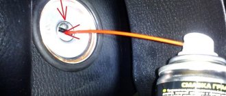
Removing the ignition switch of a Lada Priora begins with disconnecting the power wire from the negative terminal of the battery, thereby protecting ourselves from possible troubles associated with unintentional short circuits. Next, by unscrewing seven bolts, the protective cover of the steering column is removed, after which access to the ignition switch mount (four bolts with cut-off heads) is opened.
The easiest way to unscrew such screws is to use a hammer and chisel; as a rule, such a tool is needed only to “break” the screws and then they can be easily unscrewed simply by hand. If you don't have a chisel, a drill can help you remove these screws.
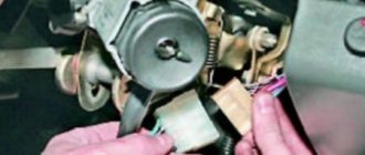
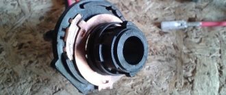
At the final stage of dismantling the lock, the immobilizer coil is removed from it and the connecting blocks are disconnected, after which it is easy to pull it out of the mounting socket.
Preventative and repair work
If it is necessary to perform preventive and repair operations, further disassembly of the switch is performed, for which three screws are unscrewed with a Phillips screwdriver and the mounting bracket is disconnected from the lock.
Please note that the removal of the locking device drive is prevented by a special cylinder stop. To successfully carry out this procedure, you do not need to completely remove the cylinder - you just need to pull out the locking ball, which is pressed by the spring. By the way, it is this spring that often causes the lock to jam, and if it fails, it can be replaced with a similar spring from the VAZ 2108 lock of the latest modifications.
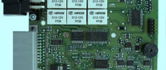
To gain access to the contact block, it is necessary to remove the switch body, and this procedure is performed by pressing the side plastic latches. On the terminal block, it is necessary to check the condition of the contacts and then remove all detected damage. If traces of scorch are found, it is removed using fine-grain sandpaper. In the event of severe, irreparable melting of the contacts, the contact group is replaced as an assembly. In this case, you will have to spend some time and solder three wires.
One of the most critical in terms of malfunctions is the terminal block. Its disassembly is also not particularly difficult - you just need to bend the latch and fold back the protective cover. Before pulling the wires out of the block, do not forget to first write down their original location. All wires and terminals are inspected for mechanical damage and oxidation that could lead to malfunctions of the lock.
The lock is assembled in the reverse order. When installing the lock, do not forget to recess the rod of the anti-theft device (otherwise installation will be impossible). To do this, you need to insert the key into the lock cylinder and move it from the neutral position “0” to any other position.
In case of a complete replacement of the lock, you should additionally replace the code elements located in the heads of the new keys with the code elements removed from the key heads of the removed ignition lock. In this case, the immobilizer training procedure will not be required.
Click to enlarge the diagram
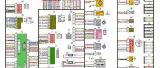
A – to the (+) “plus” terminal of the battery B1 and B2 – grounding points of the ignition system wiring harness C1 – grounding point of the wiring harness from the ignition coils
1. – M7.9.7 controller 2. – connector for connecting the ignition system harness to the instrument panel harness connector 3. – block with the main 30A fuse 4. – speed sensor 5. – electric idle speed control 6. – air flow sensor 7. – instrument sensor engine coolant temperature readings 8. – engine coolant temperature sensor 9. – throttle position sensor 10. – oil pressure warning lamp sensor 11. – rough road sensor 12. – electric fuel pump relay 13. – fuse (15 A) in the circuit electric fuel pump power supply 14. – ignition relay 15. – fuse (15 A) power supply to the ignition relay 16. – fuse (7.5 A) in the power supply circuit of the vehicle controller 17. – crankshaft position detection sensor 18. – oxygen flow sensor 19. – phase sensor 20. – knock detection sensor 21. – solenoid valve for canister purge 22. – diagnostic oxygen sensor 23. – spark plug coils 24. – spark plugs 25. – injectors 26. 26-27 – connector blocks connecting the ignition coil wiring harnesses to the harness ignition system wires 27. 28-29 – blocks connecting the ignition system wire harnesses with the injector control wire harness
On x, a Lada Priora ignition switch (lock) type 11180-3704010 with an anti-theft locking device is used, blocking the restart of the VAZ 2172 starter without first turning off the ignition and a communication coil of the ignition key transponder with the automobile anti-theft system.
- Ignition switch connection diagram (with key inserted)
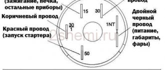
At the ignition switch, check the correct closure of the contacts at various key positions (Table 10.4), the operation of the anti-theft device and the presence of communication with the automobile anti-theft system. The voltage from the battery and the Lada Priora generator is supplied to terminal “30”.
To unload the contacts of the ignition switch, relay K4 is installed in the mounting block.
The locking rod of the anti-theft device extends if you set the key to position “0” (off) and remove the VAZ 2171 from the lock. The locking rod is retracted after turning the key from position “0” (off) to position “I” (ignition). The key can only be removed from the lock in position “0”.
The locking device for reactivating the VAZ 2170 starter should not allow the key to be turned again from position “I” (ignition) to position “II” (starter). Turning the ignition key to this position should only be possible after returning the key to the “0” (off) position.
- Switched circuits at different key positions
On Lada Priora cars, an ignition switch (lock) type 11180-3704010 is used with an anti-theft locking device, a blocking for re-starting the starter without first turning off the ignition and a communication coil for the ignition key transponder with the car's anti-theft system.
The ignition switch is checked for correct closure of the contacts at different key positions, operation of the anti-theft device and the presence of communication with the car anti-theft system.
The voltage from the battery and generator is supplied to contact “30” (Fig. 1).
Rice. 1. Connection diagram of the ignition switch (with the key inserted)
To unload the contacts of the ignition switch, a “K4” relay is installed in the mounting block.
The locking rod of the anti-theft device extends if you set the key to position “0” (off) and remove it from the lock.
The locking rod is recessed after turning the key from position “0” (off) to position “I” (ignition).
The key can only be removed from the lock in position “0”.
The starter restart locking device must not allow the key to be turned again from position “I” (ignition) to position “II” (starter).
Turning the ignition key to this position should only be possible after returning the key to the “0” (off) position.
Features of the ignition switch on Priora
The Priora ignition switch is a unit equipped with an anti-theft device and a restart blocker for the starter mechanism. As can be seen from the diagram, the voltage from the battery is supplied to output 30 of the VAZ ignition device. To ensure protection of the unit circuit, relay K4 is installed in the fuse block. When the ignition key on a Priora is set to position 0, the locking rod of the anti-theft mechanism extends. The key can only be removed in this position.
Different circuits are activated in different key positions:
- I. In accordance with the connection diagram of the connection wires, in this position the operation of the motor control system, the excitation circuit of the generator unit, optics, and alarm are activated. The instrument panel, windshield cleaning system, and power windows are also included, if included in the package.
- II. In this position, all components activated in position I work, as well as the starter device (video author: Alexey Wolf).
Interpretation of the symbols for the rear wiring harness of the VAZ Priora
The rear part of the electrical wiring chain is responsible for the vehicle's lighting and peripheral systems. This includes lights, locks and windows. The pinout of tips and terminals looks like this:
- 1 – dashboard response;
- 2 – power supply for the door behind the driver;
- 3/28 – power supply for the front passenger panel equipment;
- 4 – maintenance of power windows and door locks;
- 5-6 turn signals;
- 7 – interior lighting;
- 8 – handbrake indication switch;
- 9-10 – aft dimensions;
- 11 – temperature inside the car;
- 12-15 – circuit breakers for lighting the interior of the machine;
- 16/17 – power supply to the devices of the aft right and front left doors, respectively;
- 18/19 – voltage to the rear right and left speakers, respectively;
- 20 – cigarette lighter power core;
- 21 – EBN;
- 22 – contact group of the cargo compartment lighting circuit breaker;
- 23 – heated rear windshield;
- 24 – luggage compartment lighting lamp;
- 25 – additional stop;
- 26 – power line to the electric lock of the luggage compartment lid;
- 27 – power supply for rear number plate illumination;
- A1-4 – mass;
- ХР1/3 – electrical package power controller.
Pinout for rear license plate illumination of VAZ 2170
The small harness, located in the luggage compartment, has only three terminals:
- 1 – power supply to the stern license plate lights;
- 2-3 – license plate lighting lamps;
- 4 – trunk lid lock motor.
Pinout for the driver's door of the Priora
The harness is routed to supply power to the driver's door equipment. There is an output to the key panel installed in the armrest. There are six elements in total:
- 1 – additional terminal to the rear of the machine;
- 2 – line to the left fuse;
- 3 – electric window drive;
- 4 – armrest control module;
- 5 – door lock drive;
- 6 – rear view mirror control chip.
Front Passenger Door Wiring Harness
The unit duplicates the voltage supply from the center console to the passenger keypad located on the right side of the car. There are only seven connectors here:
- 1 – continuation of the main highway to the rear;
- 2 – terminal of the line to the right front speaker;
- 3 – window lift drive;
- 4 – electric window lift button;
- 5 – door lock drive;
- 6 – control of the position of the rear view mirror, as well as heated glass;
- 7 – continuation of the highway to the rear.
Rear door harnesses
The rear door wiring diagram has only two terminals. In this case, the side of the car is not of fundamental importance:
- 1 – continuation of the highway;
- 2 – locking drive.
Possible malfunctions of the protection system and ways to eliminate them
If the ignition switch fails on a VAZ 2170, many motorists may confuse this problem with a breakdown of the ignition coil or, for example, the ignition module. But as for the 3Z specifically, its repair or replacement is carried out only if the key is not moved to position I or the steering wheel is not blocked after the key is removed. The key must always return to position I after starting the engine. If this does not happen, then you can either repair or replace the ignition switch.
Design
The ignition switch consists of two parts: contact and mechanical. Each part performs its function and is subject to wear.
Contact part of the lock
This part is put on the lock cylinder and has several contact paths, which, when the key is turned, close and send a signal to turn on the ignition or turn on the starter.
Mechanical part of the lock
This part is the cylinder into which the key is inserted; on all cars the mechanical part of the lock is individual and the possibility of selecting a key is reduced to a minimum. It happens that on an old lock whose turning part is broken, it is possible to turn the cylinder using a similar key from another car.
Repair instructions
The location of the 3Z is known to everyone - this unit is located directly under the steering wheel. To properly replace or repair a device, you must follow the instructions:
- First, disconnect the battery and remove the plastic steering column cover, which is secured with bolts.
- Next, press out the fastening and disconnect the connector with the 33 wiring from the control panel wiring block. When unplugging, be careful not to damage the plug.
- Having done this, you will also need to disconnect the plug with the 3Z wires from the connector with the wiring of the immobilizer control system. Using a hammer and chisel or a drill, you need to remove the four breakaway screws and remove the assembly from the steering column. You can't just unscrew these bolts. VAZ engineers decided to use this method of installing the protection in order to protect car owners from possible thefts. This method of fastening, as you can guess, makes it very difficult to dismantle the protection, so at this stage you will have to tinker. In any case, the bolts can be dismantled or drilled out, but instead you will have to purchase new ones in advance.
- After completing these steps, you can bend the connector mount with wiring from the 3Z. The terminals with wires are removed from this connector. Next, you need to compress the latches again and dismantle the plastic cover of the device itself. If you plan to simply change the node, then this can be done at this stage. We suggest that you familiarize yourself with more detailed information on repairs - it is quite possible that simple steps will restore the unit’s functionality and save money.
- So, if you decide to repair the mechanism, then at this stage you need to press out two more plastic clips and remove the contact group from the cover.
- Next, it is necessary to carry out a thorough visual diagnosis of the contacts. If you notice that the contacts have oxidized or burnt, you can restore their functionality by cleaning them using fine-grained sandpaper. Get rid of oxidation and plaque, but do not go too hard so that the contacts do not wear off. If the damage to the contacts is too severe, then cleaning will not solve the problem - you will only need to change either the contactor itself or only the contact group.
- If everything worked out with the contacts, then you can assemble and install the protection. During assembly, pay attention to the position of the terminals with the wiring in the connector; under no circumstances should they be mixed up.
- After completing these steps, install the locking device back into place, while pre-sinking the locking rod of the anti-theft unit. To do this correctly, install the key in the 3Z and turn it to any position, the main thing is that it is not in the “0” position. If the key is replaced, then the transponders must also be changed - these are special electronic code components on the head of the key. If you do not do this, then you will also have to carry out the training procedure, as well as change the lock cylinder on the trunk and doors, and this is a rather labor-intensive process. Otherwise, you will have to use the old key to open the doors and trunk and the new one to start the engine. Agree, this is completely inconvenient, but this is only relevant for those car owners who have changed their license plate.
Video “Detailed instructions for replacing the seal”
Visual instructions on how to replace a unit at home are given in the video below (author - channel In Sandro's Garage).
The ignition switch on a Lada Priora car starts the engine. In order for it to start, the machine needs to be given a command. The price of a part for a Priora car is from 1,800 rubles. Replacing the ignition switch is a simple procedure that a beginner can handle.
The driver, turning the key in the lock with the immobilizer in several different positions, gives the command to turn on the ignition or start the engine. Only after this everything starts to work: the starter turns, the crankshaft begins to move, and finally the spark plugs give a spark for the first portion of the air-fuel mixture. But the operation of all these parts may not take place due to a malfunction of the ignition switch on the Priora.
If the car does not start, and you are sure that the components are working properly and the battery is charged, you will have to remove it in any case to inspect and identify the fault. Repairs can be done by anyone; it’s enough to understand all the steps in detail. If it does not help, then the ignition switch needs to be replaced.
How to change and remove it on a Lada Priora car and how many actions need to be performed, you will learn from the article.
Once the ignition switch is turned, the car remains in the ignition even when you remove the key. Unfortunately, Priora is not deprived of this; as the lock wears out, this happens.
How long it will work depends on how you use it. If you use force once, you can break the ignition switch.
Why won't the engine start?
In order for the engine to start successfully, four conditions must be met. This is a sufficient crankshaft speed, a good level of compression, sufficient battery voltage, as well as the composition of the fuel mixture. Therefore, if a Priora car does not start, we can assume that some of the conditions are not met. To check this, you should analyze the situation.
If the unit does not want to start, then the first thing that is usually checked is the starter, battery, and high-voltage wires. Is the starter working normally, are there any suspicious sounds during its operation? Have the starter or battery been replaced? If the latter is discharged, then check the generator to see how well it charges the battery. Or maybe there are some problems in the electrical part? If you answer these questions, you can easily find out where the problem lies.
Standard ignition switch - article number, price, how it works, device
The module on Priora does not work directly with the components that initiate the engine start. For it to work properly, you need to wait a few seconds before starting until the fuel pump creates the required pressure. On the Priora, only wires are connected to it - the paths along which messages pass from the ignition switch to the electronic control unit.
The ECU of the Priora car just receives data about the position of the key and can crank the starter if this operation is “not blocked”. Due to a breakdown, it can only turn on the ignition, leaving the battery to work.
After the ECU key has turned, it gives commands to several parts at once. When you turn on the second position, let the fuel pump run for 5 seconds so that it pumps fuel from the tank closer to the engine.
When the starting process itself begins, the starter rotates - the force it creates goes to the crankshaft;
the ignition system element converts the low voltage current coming from the battery into a high one so that the spark plugs are “charged” and give a spark at the right moment;
The injector creates the first batch of air-fuel mixture to put it into the chamber, where everything is ready for it - the pistons “move”, the spark plugs spark.
In the module itself, everything is simple - there is a cylinder with a return spring inside, between the coils there is a locking ball that does not allow it to curl up more than necessary, and a locking rod holds the structure in place. Finally, as a complication of the entire system, there is an “immobilizer” - an anti-theft system that you can install yourself. It just takes a long time to set it up.
A regular kit with a master key and several door cylinders (with an immobilizer) costs from 1,800 - 2,000 rubles, catalog number - 2170-3704005. A set without a master key (without an immobilizer) can be purchased for 1,200 – 1,400 rubles, article number -2170-3704006.
About the immobilizer
It should be remembered that the Priora is equipped with an anti-theft system, namely an immobilizer. This function will allow you to start the car only with the key that is in the ECU memory. All attempts to start the car engine using a duplicate key will be futile and will not lead to success, since it is necessary to register the key in the ECU memory, which requires a training key.
When replacing the lock and contact group, there is no need to retrain the immobilizer.
Diagram and pinout of the ignition switch on Priora
The diagram looks like this:
Using the diagram, you can track the presence of an immobilizer, as well as a blocker for excessive cranking of the starter. It starts from the battery - the pinout transmits voltage from it to point 30. Here the connection to K4 is a fuse relay. The contact group of the ignition switch of a Priora car will only work if the locking rod is in place and holds the key.
There are two positions in the diagram – I (ignition) and II (engine start). Replace the ignition switch of the Lada Priora in accordance with this diagram.
practical guide
To check the ignition switch you will need a multimeter.
1. Prepare the car for work and disconnect the wire terminal from the negative terminal of the battery.
2. Remove the decorative linings of the steering column.
3. By pressing the latch, disconnect the ignition switch (lock) block from the wiring harness block.
4. Using a multimeter in ohmmeter mode, check the serviceability of the terminals in the block.
Perform the test when the key is in position O - “off”, all contacts should be open. Then check the contact closure in position I - “on”, contacts 15 and 30 should be closed (resistance between terminals A and C is close to zero). In position II - “starter”, contacts 15 and 50 should be closed (the resistance between terminals C and D is close to zero).
Designation of the terminals on the ignition switch (lock) block: A - pin 30; C - contact 15; D - pin 50
We replace the ignition switch with a faulty contact group.
Add a comment Cancel reply
You must be logged in to post a comment.
Basic faults
Usually the module is “sinned” when the battery is dead - nothing will turn on, even the ECU will not receive a signal. You can solve everything by charging the battery or installing a new one. But if you are sure that the key in the ignition switch has turned, but there is no “effect”, then the problem is in the module.
- Firstly, one of the dangerous problems is a faulty locking rod. As was said, it does not allow you to remove the key when it is in position I or II. If you accidentally notice that the key falls out, try to replace the block as soon as possible. It happens that replacement is taken due to an immobilizer error. This can only be done as a last resort, having accurately checked all possible “escape routes”, because reconfiguring the ECU will take a lot of time.
- Secondly, the wiring connected to the unit may become damaged, and it will become “cut off” from the Priora’s electronic control unit. It is necessary to ring all sections of the wiring and change it. In the same group of problems is the fuse relay. If the fuse is blown, the engine will not start.
- Thirdly, the spring may become deformed or break. This manifests itself in the fact that after cranking the starter and starting the engine, the key does not return to position I.
Troubleshooting Starter Problems
The starter is an important element of the engine starting system. Its task is to ensure vigorous rotation of the crankshaft, which transmits translational motion to the piston group, creating the necessary degree of compression in the combustion chamber and removing exhaust gases.
Basic starter malfunctions:
- short circuit in the traction relay winding;
- oxidation of wire tips;
- bendix jammed;
- break or short circuit in the starter winding;
- worn or damaged starter brushes.
First, you should conduct an external inspection of the Priora starter fuse: check the condition of the contacts, clean the oxidized terminals. It is necessary to evaluate the reliability of the ground connection with the engine and body. Then you need to try to start the car again. If the Lada Priora starter traction relay clicks, but it does not spin, the breakdown needs to be repaired.
If the device fails in the field, when it is not possible to contact a service station, you can jump start the car. For this you will need an assistant. Having accelerated the car with the ignition on, you need to quickly engage second gear and release the clutch: the car starts to twitch, but after two or three jerks it starts. This is the most popular method of starting the engine when the battery is dead or the starter is faulty, but it can only be used on vehicles with a manual transmission.
Repairing the Lada Priora starter can be done by removing it from the engine: this makes it easier to carry out preventive maintenance, unlock the bendex, and replace brushes. If a winding break occurs, you need to install a new starter assembly, and it is advisable to do this on a cold engine.
Removing and installing (replacing) the ignition switch on a Priora
Before removing and replacing the module, have a few tools ready:
- chisel;
- hammer;
- pliers;
- key "10";
- Phillips screwdriver.
Replacing the Priora ignition switch is carried out according to the following algorithm:
- Put the car on the handbrake, remove the negative from the battery.
- Remove the steering column covers - to do this, insert a screwdriver into the small technical holes and unscrew the bolts.
- In front of you will be a steering shaft, to which the ignition module is attached with four bolts. They are twisted very tightly - so that potential hijackers would have to waste time removing the module; to do this, they would have to tear off all the fasteners. Place the chisel under the bolt head and tap the chisel with a hammer until the bolt head begins to rise.
- By lifting the threaded fasteners, you can unscrew them - but for convenience, it is better to do this not with your hand, but with prepared narrow pliers - there is a lot of space for standard ones.
- As you unscrew each bolt, try to “catch” the falling module.
- All that holds it is a block of wires. Disconnect it, then install a new ignition module for the Priora car instead of the old one. Tighten the fasteners just as tightly, but try not to tear them off when tightening.
Sources of the problem
Communities Lada Priora Lada Priora Club Blog what is affected by the clutch release switch The reasons why the Lada Priora does not start may be a malfunction in the fuel system:
- clogged fuel filters;
- failure of the fuel pump;
- lack of gasoline in the tank;
- clogged injectors;
- condensate freezing in the fuel line.
Having certain skills, every car enthusiast can fix these faults with his own hands. First you should check whether gasoline is supplied to the ramp with injectors. To do this, you need to disconnect the fuel hose from the rail and connect the pressure gauge. Then ask an assistant to start the engine. When the fuel pump is running, the pressure in the fuel line should be 2.7 atmospheres. If the pressure is lower than specified, you should look for the cause in the fuel filters.
A complete lack of pressure when a voltage of 12 V is applied means that the fuel pump has failed. To fix the problem, you need to replace the fine filter, wash or change the fuel pump filter, or replace its electric motor.
If the pressure in the fuel line is normal, the cause should be sought in the injector rail. You need to remove it from the engine, wash it with a special liquid and blow out all the holes with compressed air. To prevent condensate freezing from causing a lack of fuel supply, repair work should be carried out in a warm room.
List of possible malfunctions related to the operation of electrical equipment:
- Insufficient battery charge.
- Battery terminals are oxidized.
- The starter does not work.
- The traction relay is faulty.
- The timing belt is broken.
- Malfunction of the electronic control unit.
- The valve timing is disrupted.
- Severe contamination of high-voltage wires or lack of contact.
- Pulse transformers are faulty.
- The fuses responsible for the operation of the ignition system and starter have blown.
- Spark plugs are flooded or faulty.
- Burnt ignition switch terminals.
- The immobilizer is faulty.
Before you start looking for these problems, you need to make sure that the contacts and connections of all wires are reliable, that there is no oxidation, breaks or abrasions.
Lock lighting
Illumination of the ignition switch in a Priora car is a convenient modification in the dark. There are ways to tune anything inside your Priora. One of the most practical ways is to help yourself find the ignition switch by highlighting it. But getting a flashlight or phone out takes a long time and is impractical. Instead, you can put a backlight on this part, which will also be aesthetically pleasing to the car owner.
Such an upgrade can be purchased on Chinese websites - preferably only for Priora. To connect, climb under the steering casing, place the LED strip, and the wire soldered to it needs to be “powered.” When connected to contacts No. 8 or No. 9, when the dimensions are turned on, the backlight turns on.
Common breakdowns
Below is a list of the most common breakdowns.
Contact group breakdowns
Most often, the contact part in the ignition switch fails. This occurs due to the flow of large currents during starter operation. The contact tracks wear out, the reliability of the contact decreases, because of this the tracks heat up, which leads to the formation of carbon deposits on the contact. Carbon deposits on the track prevent the passage of current, thereby making it impossible to turn on the starter.
Such damage can be repaired by cleaning the tracks, but this is not always possible due to the formation of high temperatures there, which can distort the plastic.
Mechanical breakdowns
In the mechanical part, breakdowns occur due to wear of the cylinder, which leads to jamming of the rotating mechanism or to its large backlashes. This damage cannot be repaired and in case of such damage it is necessary to replace the lock with a new one with a key.
Button instead of ignition switch
As a replacement, the Lada Granta and many foreign car models have a START-STOP button. We can say that the start button is a matter of driver convenience, but if you want to make your car unique, you can use different options:
- removing the standard module - the steering wheel will not be blocked;
- The standard module remains, but the steering wheel lock does not work;
- The standard module remains in place, the steering wheel lock works.
You can supply a pre-formed kit, or assemble it yourself - it will be several times cheaper, but not faster.
The cost of the set will be from 1,300 to 1,800 rubles, individual parts in total from 300 to 500 rubles.
How to put
To place a button instead of a module, perform the following steps:
- Remove the negative from the battery.
- Remove the steering casing and the plastic panel to the right of the pedal assembly.
- In accordance with the instructions that came with the start button, connect the wires to the block.
- Connect the green cable from the central unit to the brake pedal switch connector.
- The wire from the button should be connected to the three-pin connector of the central unit.
- If you need to disable the steering lock, cut off only the part of the key that fits into the cylinder and leave it in the lock in the first or second position.
- Place the key at the junction of the casing.
- Test the Start-Stop button with a few presses.
Lada Granta Logbook Flip key
Hi all. The moment the manager at the car dealership handed me the keys to the car, I just grinned like crazy at the design of the key. Consistency is the key to success, I thought and went. Then I realized that AvtoVAZ took a step forward and there were several differences from the keys of Soviet times, but they are negligible.
Flip key housing2. For a very long time I was looking for a sting in the workshops for making keys in Ekb specifically for the VAZ. I realized that this would not be successful, I went to a normal workshop and asked the master to do something. He did not use chemicals from other blades. He suggested the following - take a VAZ key blank and cut off the excess. We measured, calculated the working area of the key, etc. And the blacksmith began to forge iron. They cut approximately along these lines3. I decided not to remove the immobilizer chip from the original key so that I had a spare (original) key. But I needed to see what was inside the key. I didn’t want to pick the key, so I turned to Internet, which said that the chip was in the grant PCF7936AS. In the store they sell it for 800 rubles, then a toad strangled me. You can buy it cheaper on the internet, but I had an almost ready-made set of switch keys, so the waiter in me died and I had to do everything urgently. I went to a garage technician who does alarms and other things. I explained to the guy what I needed, he looked for some kind of bag and gave it to me. There were 2 chips, according to him, some of them were working and some were not. For this whole thing I paid him 200 rubles. and quickly went home to collect. Only then did I notice that I had 2 PCF7936AA chips in my bag. Well, I thought it would work out - no, no trial, I’ll take him back and take my hard-earned 200 rubles.
And so I started putting it all together
Ready tip
The sting was installed in the body. After assembling it, I went into the car to register a new key.
I glued the chip to the case, approximately in the area where there is room for it inside, so that it falls within the range of the receiver. I will write the process of registering the key in a separate post, so that it is not too much of a book. I’ll just write that I didn’t see the first chip at all, but the second chip was registered the first time. I sat in the car and was happy like a child that the toy was almost ready. After registering the chip, I went home to put it in the case
The chip is inside, but it dangles like a pencil in a bucket. Therefore, I decided to put it on hot glue so that this beast would not go anywhere and would be in one place
I put everything on hot glue, but the music didn’t play for long. Only later did I realize what an inattentive cretin I was, that I filled the floor of the building with this condensed milk. How will I close the case now? After all, now the second part of the body rests against this frozen mountain of snot and does not close. Ingenuity, a stationery knife and a lighter came to the rescue
Picked off the glue around the edges
Now everything closed smoothly, pressed, twisted, went in and did not rub anything.
Ready option
What would you like to say in the end? It would probably have been easier to buy a ready-made key and go cut it, it would have cost about 2,000 rubles, but my option seemed cheaper to me (that’s how it turned out) and more correct, since now I know what, where and why. Thanks to everyone who made it to the end. No nail, no rod and good luck to everyone on the roads)))