01/26/2022 7,555 VAZ Priora
Author: Ivan Baranov
Almost all modern cars today are equipped with electric windows, which allow you to control the opening of the windows at the touch of a button. And the Russian Priors in this case are no exception. The control device, with the help of which the windows are raised and lowered, as well as many other functions, is called the Priora comfort unit. You can learn more about its structure, as well as repair, from this article.
[Hide]
What functions does the block provide?
The main functional purpose of the device is to monitor and control the electrical system in the car. Some important functions for which the block is responsible:
- fog lights, low beam, side lights;
- lighting in the car interior;
- direction indicators;
- power window system;
- operation, adjustment and heating of side mirrors;
- anti-theft system;
- signaling;
- door locking;
- trunk lighting;
- instrument panel lighting.
Partial, and even more so complete failure of the unit causes significant trouble for any car owner. The biggest problems are caused by the failure of the comfort unit in dense city traffic conditions.
Pinout of the lighting control unit on Priora
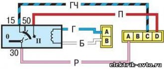
This switching and control combined module has several functions and is used to turn on/off parking lights, headlights, select the desired light switching mode, turn on/off fog lights, adjust the brightness of the backlight combination, control the headlight range control, on/off and control light inside the cabin and instrument lighting. The module is connected to the vehicle’s on-board network via chip No. 1118-3724500.
The standard terminal pinout on a VAZ 2170 is as follows:
| G, 56b | To the gear motor for adjusting headlights |
| 58b | Output to backlight sources |
| 31 | Weight |
| Xz | +12 volts (from terminal 15 of the ignition switch) |
| 56 | To the relay for switching high and low headlights |
| 1,3 | From rear and front fog lights |
| 2,4 | To the rear and front fog lamp relays |
| 58 | To the size lamps |
| 30 | +12 V from terminal No. 30 of the ignition switch |
Replacement and repair of the electrical package control unit 2170-3763040 Lada Priora
Priora electrical package control unit 2170-3763040 (Comfort unit) The vehicle equipment, as is sometimes written, does not matter when a unit with this number is installed.
The electrical package controller is a device designed for installation on VAZ 2170 Priora cars. It controls many car functions, for example, turn signals, power windows, instrument panel lights, side lights, low beam, fog lights, reverse lamp, interior lighting, heated rear window.
This controller is installed in the central, lower part of the dashboard above the ECU unit. To remove it, you need to remove the lower sides of the torpedo. Using a socket wrench 10, unscrew the two nuts.
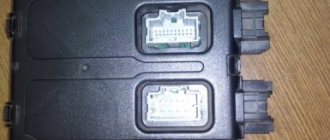
Priora electrical package control unit housing 2170-3763040
Priora electrical package control unit board 2170-3763040
Location of terminals of the Priora electrical package control unit 2170-3763040
Diagram of the Priora electrical package control unit 2170-3763040
Purpose of parts on the board of the Priora electrical package control unit 2170-3763040
POS - interior lighting lamp ZPTO - rear fog lights BS - low beam PTF - fog lights MDV - driver's door module PUP - turn signal switch PAS - hazard warning switch PPD - front right door PLD - front left door ZPD - rear right door ZLD - rear left door PS - passenger door power window switch FOB - trunk light ZP - right mirror ZL - left mirror GO - side lights UP - direction indicators
Problem with the electrical package control unit 2170-3763040 Priora:
Priora electrical package control unit 2170-3763040 old
After turning on the heated rear window, a malfunction occurred in the operation of this unit. The IMMO started flashing, the emergency lights came on - it’s impossible to turn it off. After turning off the heating, the turn signals and emergency lights, mirrors stopped functioning, the central locking stopped working, both from the key and from the buttons in the cabin, the tidy went out, and the power windows stopped working.
A new electrical package control unit 2170-3763040 Priora was installed:
Electrical package control unit 2170-3763040 new
The procedure for removing and installing the block is simple. There is no need to retrain the key, everything works. The only thing is that the two-level door opening system stopped working. Now one click opens two doors. or one press and only the driver's door opens, a second press and the passenger door does not open... Strange.
Repair of the electrical package control unit 2170-3763040 Priora: In the old unit, for the sake of experiment, two VN5016AJTR-E power driver microcircuits (SSO-12) were replaced
Resoldering the VN5016AJTR-E chips did not bring any results.
Resoldered chip: MCZ33972EW
Chip MCZ33972EW for replacement.
What is a CAN bus and what is it for in Lada Priora
A modern car, unfortunately or fortunately - it’s up to you to decide, is no longer the same box on wheels with fifteen
Purpose of CBKE
The TsBKE block is designed to perform the following functions
:
- alarm system;
- control of the windshield wiper in the “manual control” mode;
- control of the windshield wiper in the “automatic control” mode (for TsBKE 21900-3840080-20);
- windshield defroster control;
- control of the rear window heater and electric side mirror heaters;
- control of low beam headlights, side lights and daytime running lights in the “manual control” mode, provided for by UNECE Regulation No. 48-04;
- control of low beam headlights, side lights, daytime running lights in the “automatic control” mode (for TsBKE 21900-3840080-20);
- control of daytime running lights in accordance with UNECE Regulation No. 48-04;
- high beam headlight control;
- control of direction indicator and hazard warning lamps;
- interior lamp control;
- energy saving control of vehicle interior lighting devices;
- central locking: locking/unlocking the side door locks from the key, from the driver's door lock button from the passenger compartment, from the button in the driver's door module;
- opening the trunk lid (tailgate) from a button in the cabin;
- control of electric window lifters;
- remote control;
- control of electric drives of side mirrors (for TsBKE 21900-3840080-20);
- front seat heating control;
- indication;
- trunk lighting control (for TsBKE 21900-3840080-20)
We told you earlier where the TsBKE block is located.
Ignition system diagram Lada Kalina Lux
1 — oil pressure warning lamp sensor;
2 — coolant temperature indicator sensor; 3 — additional fuse block; 4 — fuses for the electric fan of the engine cooling system; 5 — electric fuel pump relay; 6 — relay for the electric fan of the engine cooling system; 7 - ignition relay; 8 — relay 2 of the electric fan of the engine cooling system; 9 — relay 3 of the electric fan of the engine cooling system; 10 — electric fan of the engine cooling system; 11 — throttle position sensor; 12 — idle speed regulator; 13 — coolant temperature sensor; 14 — diagnostic block; 15 — ignition system harness block to the instrument panel harness block; 16 — solenoid valve for purge of the adsorber; 17 — speed sensor; 18 — ignition system harness block to instrument panel harness block 2; 19 — mass air flow sensor; 20 — crankshaft position sensor; 21 — oxygen sensor; 22 - controller; 23 — rough road sensor; 24 — diagnostic oxygen sensor; 25 — ignition coil harness block to the ignition system harness block; 26 — ignition coils: 27 — ignition system harness block to the ignition coil harness block; 28 — spark plugs; 29 — nozzles; 30 - resistor; 31 — air conditioning system pressure sensor; 32 — blocks of the ignition system harness and injector wiring harness; 33 - phase sensor; 34 - knock sensor. Ignition system wiring harness -11184-3724026-10. Ignition coil wiring harness -1118-3724148-00. Injector wiring harness -11184-3724036. A - to the “plus” terminal of the battery.
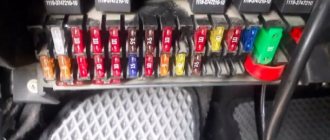
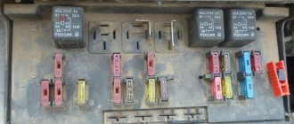
Mounting block fuses
| Fuse designation | Rated current, A | Electrical circuit |
| In the “Norma” package | ||
| F-1 | 25 | Radiator fan |
| F-2 | 25 | Rear window defroster |
| F-3 | 10 | High beam lamp (right) |
| F-4 | 10 | High beam lamp (left) |
| F-5 | 10 | Signal |
| F-6 | 7,5 | Low beam headlight bulb (left) |
| F-7 | 7,5 | Low beam lamp (right) |
| F-8 | 10 | Signal |
| F-9 | 25 | Electric stove fan motor |
| F-10 | 7,5 | Interior lighting, instrument panel lighting, brake light lamps |
| F-11 | 20 | "Windshield wipers" (control) |
| F-12 | 10 | Connector “15” of the instrument panel |
| F-13 | 15 | Cigarette lighter |
| F-14 | 5 | Side lamp (left headlight) |
| F-15 | 5 | Side lamp (right headlight) |
| F-16 | 10 | Connector "15" ABS |
| F-17 | 10 | Left fog lamp |
| F-18 | 10 | Right fog lamp |
| F-19 | 15 | Front seat heater |
| F-20 | 5 | Immobilizer control module |
| F-21 | 7,5 | Fog lights (rear) |
| F-22–F30 | Reserve sockets | |
| F-31 | 30 | Electric package control module |
| F-32 | Reserve socket | |
| Available in “Lux” and “Lux Plus” configurations | ||
| F-1 | Reserve socket | |
| F-2 | 25 | Rear window heater, electrical package module, relay and connector “10” for connecting the rear window heater |
| F-3 | 10 | High beam lamp (right), instrument panel, high beam warning lamp |
| F-4 | 10 | High beam lamp (left) |
| F-5 | 10 | Protection of the mounting block, signal and its relay |
| F-6 | 7,5 | Low beam (left headlight) |
| F-7 | 7,5 | Low beam (right headlight) |
| F-8 | 10 | Anti-theft alarm relay, anti-theft alarm horn |
| F-9 | Reserve socket | |
| F-10 | 10 | Brake light switch, brake light lamps, connector "20", interior lighting |
| F-11 | 20 | Windshield wiper mode switching module relay, wiper mode switch, connector “53A”, rear window heater relay, rear window wiper motor (for VAZ-2171, 2172), connector “25” of the front airbag control module |
| F-12 | 10 | Connector “21” of the instrument cluster, connector “9” of block X2 of the dashboard, connector “1” of block X2 of the electric power steering control module, reversing headlight lamps, parking sensor control module |
| F-13 | 15 | Cigarette lighter |
| F-14 | 5 | Left side light, trunk light, warning light for license plate light, connector “12” of block X2 of the glass unit control module |
| F-15 | 5 | Right side light, glove box light |
| F-16 | 10 | Hydraulic unit of the ABS system |
| F-17 | 10 | Fog lamp (left headlight) |
| F-18 | 10 | Fog lamp (right headlight) |
| F-19 | 15 | Heated front seats relay |
| F-20 | 10 | Side and low beam relay, heater fan relay, lighting control relay, windshield wiper control module, climate system control module |
| F-21 | 5 | Connector “30” of the light alarm switch, connector “16” of the diagnostic block, clock, connector “14” of the automatic climate control unit |
| F-22 | 20 | Wiper motor, wiper motor relay, wiper control module relay |
| F-23 | 7,5 | Connector “20” of the wiper control module |
| F-24 - F-30 | Backup fuse sockets | |
| F-31 | 30 | Connector “2” of block X1 of the electrical package module, threshold illumination lamps |
| F-32 | Reserve fuse socket |
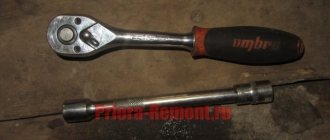
New Lada: Bosch, Brisk, Denso, NG, DVRM spark plugs for Lada Priora - which ones to choose and how to replace. To remove the mounting block from the seat, you only need a screwdriver with a Phillips-head bit. She needs to unscrew the screw securing the block, then, pulling it towards you, disengage it from the fastening hooks.
Before replacing relays and fuses, you must disconnect the negative terminal from the battery. To remove the main unit, you will need to disconnect all terminals with wires connected to it, having previously marked their location.
Malfunctions in the operation of the comfort unit, how to eliminate them
- The turn signals do not light up. First, you should check the continuity of the fuse, lamps and steering column switch. If there is simply no contact somewhere, then the problem can be resolved very simply by resoldering the microcontacts. If there is a fault in the board itself and soldering the contacts does not help, then the controller should be replaced.
- The power window module or central locking does not work. This problem can also occur due to oxidation of the wires. Before removing the comfort unit, you need to check all the wires with a multimeter under the insulation in the control unit, which is built into the driver's door. If only one glass unit is faulty, the wires could become disconnected due to a broken contact.
After checking the wires, if the problem cannot be found. The DA7VN5016A or DA6VN5016A controller should be re-soldered. One of them is responsible for the double-glazed windows and the lock on the right door. The second mirrors the same functions, but on the left side.
Sometimes window lifters only work to lower the windows, but raising them is not available (or vice versa). To do this, check the connection so that all the pros and cons are in place.
Errors occur in the comfort unit when the window lift button to raise the window works to lower the window. With different polarities, when the glass rises instead of lowering, you need to change the connection of two adjacent wires.
- It happens that many problems arise at the same time. The fog lights, side lights, rear lights, heated rear glass, and interior light stop working. In this case, it is obvious that the problem comes from the comfort unit and the DA1 MC33972EW variant is re-soldered. If this does not help, then the entire circuit should be replaced.
- In case of failure of the rear fog lights and instrument lighting in the cabin, the DA9 VND5025AK component is re-soldered. And, as was the case with previous breakdowns. If this does not bring results, the entire scheme is changed.
- The central locking locks begin to operate when the power window keys are pressed. If replacing the comfort unit from another car does not bring any effect, then the essence of this breakdown is in the wiring. To do this, you need to carefully check the integrity of all wires leading to the comfort unit.
Possible causes of malfunctions
Before purchasing a new comfort unit, you need to try to eliminate any malfunction. In order not to make additional costs, because the comfort unit is quite expensive. Often the problem is simply a lack of contact due to aging or chafing of the wires.
Sometimes the comfort unit controllers can burn out, for this you need to inspect them visually or even check them using your sense of smell.
The most common complaints regarding the operation of the comfort unit are the failure of double-glazed windows, turn signals or dimensions.
All problems can occur due to the following events
- break on the W-Line communication line;
- combustion of regulation drivers;
- burnout of controllers responsible for the desired area;
- transponder malfunction;
- burnout or oxidation of contacts.
Before carrying out repair work, to comply with safety precautions, do not forget to disconnect the negative terminal from the battery.
How to change the bulbs in the headlight of a VAZ 2170
To replace the low beam bulb, wear clean gloves and disconnect the battery.
Then remove the rubber protective cap, which is located closer to the fender.
Carefully disconnect the wires.
- Remove the latch (to do this, press down and remove it from behind the hooks).
- Remove the lamp and install a new one. Installation is carried out in reverse order.
Replacing high beam bulbs is no different.
If you frequently drive at night, especially in bad weather, make sure you always have a spare set of light bulbs in your car. Probably every driver has experienced the fact that one lamp burns out at night and the lighting becomes much worse. You also endanger other road users, since it is difficult to assess the situation during the same overtaking when one of the headlights of the oncoming car is not on.
To replace the bulbs in the rear light, you will need to dismantle it. (see Replacement of the rear light)
Remove the taillight and turn the parking lamp (in the Priora, the parking light is combined with a double-filament fog lamp).
Remove the lamp by turning it counterclockwise.
Install a new one. Make sure that the tabs on the plinth fit into the grooves on the parton. All other lamps are changed in the same way.
To replace the rear license plate lamp on a Lada Priora you need:
Remove the lock trim.
Unscrew the trunk lid attachment, which is secured with 4 bolts
Remove the socket and change the light bulb.
If you cannot remove the cartridge itself, remove the flashlight itself
To do this, you need to bend the plastic clamp a little (Caution, they are very fragile). After this, you can apply a little more force to unscrew
Install everything in reverse order
If you want to change the trunk light bulb, then:
Pull the lantern out of the opening as in the picture below.
- Bend the antennae that hold the lamp and change it.
- Reinstall the lantern in its original location.
At this point the repair can be considered complete. Connect the battery and check operation. If the replacement does not help, then most likely you should check the wiring.
Where is the Priora comfort block located?
To gain access to the product, you will need to unscrew the protective plastic walls of the car's center console. They are located on the left side of the front passenger seat and on the right of the gas pedal, on the driver's side. The device itself is located above the control unit. In order to remove the device you will need a 10 mm wrench and a Phillips screwdriver.
Pinout of the Priora comfort block
The main, important elements of the device are:
- The so-called control drivers. Each driver is responsible for a set of specific functions.
- Transponder receiver.
- Relay control.
- Transceiver. Communicates with the module installed in the door.
- 2 connectors. The first is responsible for supplying power, the second for transmitting the necessary technical information.
Click to enlarge
To ensure proper operation of all elements connected to the comfort unit connectors, it is necessary to study the correct pinout (numbered diagram for connecting wires to contacts). The design of the comfort block for the Priora, when studied in detail, is not particularly difficult.
pinout, electrical package control controller and circuit
Almost all modern cars today are equipped with electric windows, which allow you to control the opening of the windows at the touch of a button. And the Russian Priors in this case are no exception. The control device, with the help of which the windows are raised and lowered, as well as many other functions, is called the Priora comfort unit. You can learn more about its structure, as well as repair, from this article.
Description of the electrical package control unit
The electrical package controller in Priora is a device used to control the functionality of the vehicle. This unit is responsible for the operation of turn signals, power windows, control panel lighting, dimensions, fog lights, interior lighting, and rear window heating system. This device also ensures the normal operation of the reversing lights. The fact that the car is equipped with this device makes it even more practical.
Location
The control device on the Priora is located above the electronic engine control unit, at the bottom of the center console, in the middle. In this case, the device is connected using two connectors - power and information. The power output is used to supply voltage to the control unit, and the information output is used to perform the functions of the device. It should also be noted that the control unit is protected from external influences of dirt and moisture.
Possible malfunctions and ways to eliminate them
What malfunctions may occur in the operation of the electrical package controller:
- Turn signal failure. First of all, you need to diagnose the serviceability of the fuse, light bulbs, and the steering column switch. It is quite possible that the contact in the switch itself is broken; the problem can be solved by resoldering the contacts or replacing it. If this does not help and the problem really lies in the board, then there are two options - either resoldering it in accordance with the diagram, or replacing it. Usually, soldering is done first, and if it does not help, then the controller itself is changed.
- The power windows don't work. Before getting into the circuit, you need to make sure that the problem does not lie in other elements. As in the previous case, first check the fuse, and then diagnose the power window control unit, it is built into the driver's door trim. If only one window regulator does not work, then most likely the contact on the unit has simply come loose and needs to be reconnected. Sometimes the problem lies in a broken or broken wire, in which case the circuit needs to be restored. If this does not help, then the DA7VN5016A or DA6VN5016A controller is resoldered. The first is responsible for the operation of the power windows and central locking on the right doors, and the second is responsible for the same elements, only on the left door. Both elements are marked in the diagram for clarity. The problem with the central locking is solved in a similar way if it does not work. Also pay attention to the DA11L9848 controller - it is responsible for the operation of the lift control relay. So if the relay does not work, but the contacts of its seat are intact, then perhaps the problem lies with this controller.
- At the same time, the side lights, front and rear fog lights, interior lights, reversing lights, and the rear window heating system stopped working. If these components stop working at the same time, then there is no doubt that the problem lies in the electrical package control unit. In this case, the DA1 MC33972EW controller is resoldered, since it is he who is responsible for the operation of these components. If resoldering does not help, then the entire circuit changes.
- If the rear fog lights and the dashboard lights do not work, then most likely the culprit is the DA9 VND5025AK controller. You can also try to re-solder this component, but if re-soldering does not produce results, then it will need to be completely changed.
Scheme of operation and troubleshooting of window regulators
There are cases when, due to a relay malfunction or a blown fuse, the Priora's power windows stop functioning on the rear doors or on the driver's right. Often the smoothness of their work turns into a pulsating state. What to do in this case? This is a traditional malfunction in VAZ cars; it occurs more often in early production models that have a power window control unit with a built-in ESP electronic unit. This problem is caused by burnt-out electric drive microcircuits or a faulty fuse, which was the result of imperfections in the microcircuit itself. Subsequently, some defects were eliminated by the plant, but the frequency of unit failure is high. But this does not mean at all that one can immediately conclude that the unit is faulty and its subsequent replacement. The reason for this behavior of the window regulators may be completely independent of the operation of the unit itself.
First of all, you need to check how the lock that controls the door lock works. If there is something wrong with the lock, check the existing plus or minus on the wire coming from the control unit from connector X1, pin 4 or 6, or check the fuse. You need to connect the control lamp to the car body and check how the windows move in both directions. Do the same with a positively charged wire. Wires 1,5,11, 13 are checked in the same way. If the control light lights up in all cases, the fault should not be looked for in the block. The wire may be squashed or the electric drive may break.
To check what exactly is faulty, you need to connect the control light located under the door trim with the wires from the electric drive. If the electric drive is broken, the light will be on; if not, then the wire is damaged. If the unit fails, the cause may be the usual contact of a bare wire either with the housing or with another wire.
The power window system in the driver's door is somewhat different in connection from the passenger doors. The main difference is in the generating control module, which controls the remaining doors. When any button on the block is turned on, a command is sent from the module to the controller. It is transmitted using a wire that connects pin 5 of the main driver unit to pin 5 of block 3 of the window regulator unit.
Self-repair of the Priora comfort unit, is this possible?
If you have never encountered soldering, diagnostics of printed circuit boards of varying complexity and configurations, or do not have the necessary diagnostic or soldering equipment, then it is better to address the repair question to qualified specialists. If you have the above skills and understand the causes of malfunctions, independent repairs are carried out quite often. This is due to the fact that various microcircuits or chips constantly fail. For example, having established that the reason for the turn signal failure is a failed control driver, it is always possible to purchase a new part and simply re-solder it to replace the faulty one.
Malfunctions and their possible causes
The cost of a new, original unit is quite high, so do not rush to buy a new product, figure out the causes of the malfunctions. Of course, there are always cases when the board cannot be repaired and it is more advisable to simply install a new product to replace the faulty one. Do not forget that the causes of malfunctions can be frayed or broken wires that are connected to energy consumers.
According to statistical data collected on technical support forums, car owners quite often complain about malfunctions in the operation of power windows, turn signals, and parking lights.
If we talk about the components of the printed circuit board itself, the most common breakdowns are associated with: - a break in the W-Line communication line; — burnout of control drivers; — burnout of controllers responsible for correct operation; - the output of their transponder; — significant oxidation of contacts.
"Important! Before carrying out any electrical work, disconnect the power supply by disconnecting the negative terminal of the battery."
Schematic diagram (pinout) of connecting the front wiring harness on the Priora
The front part of the vehicle's electrical circuit is designed to supply voltage to the primary and auxiliary power circuits of the vehicle's on-board systems. The decoding of contact group chips is as follows:
- 1 – starter power supply;
- 2 – battery;
- 3 – charge supply from the generator;
- 4 – connecting block for the bundle (1 – 3);
- 5-7 – power supply to the device;
- 8 – engine compartment lighting lamp;
- 9-10 – head light;
- 11 – brake expansion tank level indicator;
- 12 – outside temperature;
- 13 – washer drive;
- 14 – external indication of reverse gear;
- 15 – cooling system fan;
- 16 – stove reducer;
- 17 – reserve resistor;
- 18 – wiper drive;
- 19 – interior relay and fuse module;
- 20 – stove motor;
- 21 – sound alarm indicator;
- 22 – horn power supply;
- A1/2, B1/2 – mass.
Interpretation of the symbols for the rear wiring harness of the VAZ Priora
This part is organized to supply power to the main instruments and engine control system of the Lada Priora. From here, voltage is supplied to the main components, units of the vehicle’s power plant, as well as control sensors and ECUs. The standard electrical circuit connection system (pinout) looks like this:
- 1 – ECU power supply;
- 2 – main block of the electronic system to the dashboard;
- 3 – distribution board;
- 4 – speedometer;
- 5 – road surface roughness sensor;
- 6 – indication of pressure in the engine crankcase;
- 7 – TPS;
- 8 – DTOZH;
- 9 – indication of antifreeze temperature sensor;
- 10 – mass air flow sensor;
- 11 – control XX;
- 12 – main relay of the fuel pump;
- 13 – VT circuit fuse;
- 14 – relay BZ;
- 15 – fuse of the above circuit;
- 16 – ECU fusible link;
- 17 – DPKV;
- 18 – power supply for mass air flow sensor;
- 19 – phase distribution;
- 20 – mixture detonation sensor;
- 21 – EMC for purging the adsorber;
- 22 – diagnostics of the air flow sensor;
- 23 – power supply to the ignition coil;
- 24 – supply voltage to spark plugs;
- 25 – power supply to fuel injectors;
- 26 – terminal from the ignition coils to the ECM;
- 27 – feedback from 26;
- 28 – ECM connector to the injection system;
- 29 – response to the previous output;
- A – phase on the battery;
- B1/2 – ignition mass;
- C1 – mass from short circuit.
The rear part of the electrical wiring chain is responsible for the vehicle's lighting and peripheral systems. This includes lights, locks and windows. The pinout of tips and terminals looks like this:
- 1 – dashboard response;
- 2 – power supply for the door behind the driver;
- 3/28 – power supply for the front passenger panel equipment;
- 4 – maintenance of power windows and door locks;
- 5-6 turn signals;
- 7 – interior lighting;
- 8 – handbrake indication switch;
- 9-10 – aft dimensions;
- 11 – temperature inside the car;
- 12-15 – circuit breakers for lighting the interior of the machine;
- 16/17 – power supply to the devices of the aft right and front left doors, respectively;
- 18/19 – voltage to the rear right and left speakers, respectively;
- 20 – cigarette lighter power core;
- 21 – EBN;
- 22 – contact group of the cargo compartment lighting circuit breaker;
- 23 – heated rear windshield;
- 24 – luggage compartment lighting lamp;
- 25 – additional stop;
- 26 – power line to the electric lock of the luggage compartment lid;
- 27 – power supply for rear number plate illumination;
- A1-4 – mass;
- ХР1/3 – electrical package power controller.
The small harness, located in the luggage compartment, has only three terminals:
- 1 – power supply to the stern license plate lights;
- 2-3 – license plate lighting lamps;
- 4 – trunk lid lock motor.
The harness is routed to supply power to the driver's door equipment. There is an output to the key panel installed in the armrest. There are six elements in total:
- 1 – additional terminal to the rear of the machine;
- 2 – line to the left fuse;
- 3 – electric window drive;
- 4 – armrest control module;
- 5 – door lock drive;
- 6 – rear view mirror control chip.
The unit duplicates the voltage supply from the center console to the passenger keypad located on the right side of the car. There are only seven connectors here:
- 1 – continuation of the main highway to the rear;
- 2 – terminal of the line to the right front speaker;
- 3 – window lift drive;
- 4 – electric window lift button;
- 5 – door lock drive;
- 6 – control of the position of the rear view mirror, as well as heated glass;
- 7 – continuation of the highway to the rear.
Read more: Connecting a Pioneer radio by wire colors, diagram and video instructions
Rear door harnesses
The rear door wiring diagram has only two terminals. In this case, the side of the car is not of fundamental importance:
- 1 – continuation of the highway;
- 2 – locking drive.
Types of compatible window regulators
One of the most common models on the aftermarket is the window regulator for the Priora Forward. This model of electric lift is made in a combined arrangement of the drive and the actual rack-and-pinion lifting mechanism, compactly combined with the glass guide. Lifts of this model are characterized by increased reliability and ease of installation on Priora.
Garnet is the second most popular system. Under this name there is not even a single model, but a whole family, each modification of which is intended for a specific car. The mechanism is also rack and pinion type and has earned many good reviews from car enthusiasts. This type of lifts is characterized by uninterrupted operation, fast speed of raising/lowering the glass, and low noise.
It has already been said above about glass closers. In the luxury package they are available on all doors, but their performance leaves much to be desired. It is necessary to resort to replacement with other similar devices. One of the available alternatives is the Master system. It allows you to automatically raise the windows when the anti-theft system is turned on, and even control them within half an hour from the moment the ignition is turned off. The device itself looks like an electronic board with connectors connected to the standard Priora wiring.
The master is not very expensive (from 700 rubles), and its installation does not affect the door trim in any way. The whole procedure consists of removing the rear door sill trims, bending the sound insulation and connecting the door closer to the connector.
For the front doors, the Master will by default raise and lower the windows without ignition, and for the rear doors you need to install a slightly different version, called Master Plus. There are no differences in installation, the main thing is not to forget to disconnect the negative battery before starting work. The wizard has many other useful functions, for example, it automatically turns off the radio when the car is armed.
Location of the comfort controller in the cabin
You need to know that there are two options for the location of this device:
- On the first Priora models it is under the beard.
- On subsequent ones, to the left of the mounting block.
When these cars appeared, the comfort unit was installed in the area of the electronic control unit. That is, under the “beard”. If you open the decorative plastic cover located at the passenger’s left foot, you will see the Priora control unit with attached relays. Directly above them is a comfort unit (electrical package).
On subsequent cars this unit was positioned slightly differently. At the driver's left foot, with the instrument panel cover removed under the steering wheel, there is a fuse and relay assembly. Or - a mounting block. And behind it, at the wall of the body, the electrical package is mounted. Access to it is quite difficult.
Removing the comfort block on new models
If you follow the manufacturer's technological instructions, this is a very complex and time-consuming process. Suffice it to say that according to this scheme it is necessary to partially dismantle the entire dashboard of the Priora. Of course, experienced locksmiths do not do this. The process goes as follows. The negative terminal of the battery is removed.
After this, remove the decorative panel under the steering wheel. It is secured at the bottom with 3 plastic swivel fasteners. The mounting block will become available. Now comes the most difficult part. You will need a 10mm bell key. This is the most convenient option for this job.
You'll have to climb and grope with your hand. As already mentioned, the electrical package controller is screwed behind the mounting one. It is perpendicular to it. It is secured with two bolts
heads 10. Before unscrewing them, you need to disconnect the three wiring harnesses connected to the block. It is not difficult. And it is impossible to confuse them during installation. They have different entry options. After this, you can remove the mounting bolts. Since the ears on the device are not closed, but have a free exit, one of the bolts can only be loosened 3-4 turns. And then take out the block.
Install the new one in the same way.
Replacement on the first Priors
This is generally a simple operation. The shield is removed from the bottom of the “torpedo” on the passenger side. The comfort controller is perfectly accessible. Unscrew the fasteners in the same way and remove the device. Replace with new one. The only thing is that the wiring harnesses are on the driver's side. But it is just as easy to remove the side panel, which is secured with 1 bolt.
How to remove the front window lift mechanism assembly
The first step is to perform the following procedure: After this, unscrew the two bolts securing the glass to the bracket on the lift. The bolts will only be accessible when the glass is raised up. This is clearly shown in the photo below.
To prevent the glass from falling down during this repair, it is necessary to fix it by placing something between it and the inside of the door. Next, you can unscrew all the power window mounting nuts.
This mechanism is attached in several places:
- from above, in the place where the glass is fixed, and also a little higher in the very corner of the structure
- below also in the corner
- and closer to the center of the door where the motor is installed - there are three nuts
Then disconnect the plug with the power wires by simply pulling both ends to the sides with a little force.
It is through this that the entire structure should be removed from the door, which will be clearly shown in the photo.
And we remove it completely out so that further manipulations can be carried out.
The main functions performed by the electrical package control unit (comfort unit)
In fact, this device is a multifunctional control computer. His responsibilities include ensuring the functionality of many Priora functions:
- Electric windows.
- Adjusting the side mirrors.
- Turn and hazard warning lights.
- Anti-theft system.
- Door locking from the driver's door remote control.
- Lighting module.
So many options require precise operation of the Priora comfort controller.
How to disarm the electrical package unit of LADA PRIORA
What to do if Priora is not removed from the standard alarm!
The hazard warning light blinks, the car does not respond to the ignition key buttons. As a rule, several units are involved here that are synchronized with each other.
- Ignition
- Radio channel module (Located in the driver's door)
- Electrical package block (Comfort block)
- Engine ECU
New blocks come with non-activated codes inside and can be installed on any car without problems, but once you register (train) the keys, a special code is written into all these blocks, which is synchronized with each other and serves as a standard alarm system. (Immobilizer) As soon as you turn the ignition key, within five seconds there is a poll between the key and the units, if the code matches everywhere, then the engine ECU gives permission to start, if the code of at least one device is not recognized, the engine ECU is blocked and the car does not start.
Training a working key is done using a special red training key. I will not describe the procedure for training keys; there is plenty of information on the Internet. In fact, the main key is a red training key; it stores a code that, after training, is written into the working key and other blocks.
I'll try to explain in more detail how it all works:
- The radio channel code that we use to open doors using the key's remote control buttons is written into the driver's door module, where the power window buttons are located. If you replace the comfort unit or engine ECU, the buttons on the key will still work.
- The IMMO (Immobilizer) code has a connection only with the ignition key, the electrical package unit and the ECU unit. If you disconnect the driver's door module, the car will still start.
How to determine whether the keys are trained or not:
- The IMMO lamp on the instrument panel goes out after 5 seconds - the keys are trained.
- The IMMO lamp goes out after 30 seconds - the keys are not trained. (The car will start with any blank)
Replacing the Priora comfort unit
Before purchasing a new product, you must be sure that the cause of the malfunction lies precisely in it. To do this, you can install a known-good unit in your car and test the operation of problematic units. If, with a new, serviceable device, electrical consumers operate normally, the old comfort unit is faulty. Otherwise, use an integrated approach, check fuses, relays, wiring, and all kinds of drives. In other words, the entire technical chain with which the faulty unit usually comes into contact during operation.
Replacement of the device is carried out in 7 simple steps:
- We put the car on the parking brake.
- Open the hood, loosen the negative terminal and remove it from the battery.
- We move into the car interior. For ease of operation, we roll the front seats back into the cabin as far as possible.
- We prepare the tool. Using a screwdriver, unscrew the mounting bolts and remove the 2 side walls.
- Using a 10mm wrench, unscrew the two fastening nuts.
- Carefully remove the block itself. When removing, rotate the product so that it does not hit other elements. Disconnect two contact connectors, the first is power, the second is information.
- Remove the faulty product and install a new one.
In the future, in order to inspect, diagnose or repair the Priora comfort unit, you will need to remove its protective housing. When purchasing a new unit, keep your sales or sales receipt. If you purchase a faulty device, this will allow you to return or exchange it for a new one. Prices for the product vary depending on the specific seller and range from 2,500 rubles to 10,000 rubles.
Central lock VAZ 2114 Central lock VAZ 2114 (hereinafter referred to as CZ) is a mechanism018.8k.Electrical equipment
Replacing the ignition module on a Granta The ignition module of the Lada Granta is an important component012.1k.Miscellaneous
Heater cables VAZ 2114 Winter has come and you are looking forward to a comfortable and warm trip211.5k.Electrical equipment
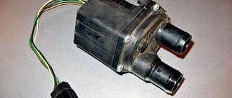
Cooling fan Priora Cooling fan Priora is the most important element010.6k.Electrical equipment
Turning relay on Grant It happens that during the operation of the car 010.1k. You may also like
TPS on Priora Modern cars are controlled and controlled06k.
Crankshaft sensor Lada Priora A car is a collection of complex interacting components03.1k.
How to start a Priora without an ignition key You are the owner of a Priora and don’t know how to start it03.4k.
Rain sensor on the Priora The rain sensor (on the Priora) is an automotive element04.7k.
Cooling fan Priora Cooling fan Priora is the most important element010.6k.
Phase sensor for Lada Priora Phase sensor for Lada Priora or distribution position 02.9k.
Clutch sensor on Priora The popular “Priora” is designed in the spirit of the times04.2k.
Eliminating heater noise on a Priora The heater of modern cars works well enough15.9k.
Replacement of the Lada Priora comfort unit. Pinout and repair
The electrical package control unit, or the so-called Priora comfort unit, is a complex electrical device. Its basis is a printed circuit board with numerous microcircuits, relays, control drivers and other elements soldered to it.
The control unit (hereinafter referred to as the product) is installed directly in the car, so its components (microelectronics) are exposed to negative influences. For example: cold, active shaking, temperature changes. As a result, certain elements burn out on the board, the integrity of the contact group is disrupted, which leads to the failure of many vehicle functions important for the daily operation. Unfortunately, in many Lada Priora cars, failure of the electrical package control system has become a fairly common occurrence.
What functions does the block provide?
The main functional purpose of the device is to monitor and control the electrical system in the car. Some important functions for which the block is responsible:
- fog lights, low beam, side lights;
- lighting in the car interior;
- direction indicators;
- power window system;
- operation, adjustment and heating of side mirrors;
- anti-theft system;
- signaling;
- door locking;
- trunk lighting;
- instrument panel lighting.
Partial, and even more so complete failure of the unit causes significant trouble for any car owner. The biggest problems are caused by the failure of the comfort unit in dense city traffic conditions.
Where is the Priora comfort block located?
To gain access to the product, you will need to unscrew the protective plastic walls of the car's center console. They are located on the left side of the front passenger seat and on the right of the gas pedal, on the driver's side. The device itself is located above the control unit. In order to remove the device you will need a 10 mm wrench and a Phillips screwdriver.
Pinout of the Priora comfort block
The main, important elements of the device are:
- The so-called control drivers. Each driver is responsible for a set of specific functions.
- Transponder receiver.
- Relay control.
- Transceiver. Communicates with the module installed in the door.
- 2 connectors. The first is responsible for supplying power, the second for transmitting the necessary technical information.
Click to enlarge
To ensure proper operation of all elements connected to the comfort unit connectors, it is necessary to study the correct pinout (numbered diagram for connecting wires to contacts). The design of the comfort block for the Priora, when studied in detail, is not particularly difficult.
Self-repair of the Priora comfort unit, is this possible?
If you have never encountered soldering, diagnostics of printed circuit boards of varying complexity and configurations, or do not have the necessary diagnostic or soldering equipment, then it is better to address the repair question to qualified specialists.
If you have the above skills and understand the causes of malfunctions, independent repairs are carried out quite often. This is due to the fact that various microcircuits or chips constantly fail.
For example, having established that the reason for the turn signal failure is a failed control driver, it is always possible to purchase a new part and simply re-solder it to replace the faulty one.
Malfunctions and their possible causes
The cost of a new, original unit is quite high, so do not rush to buy a new product, figure out the causes of the malfunctions. Of course, there are always cases when the board cannot be repaired and it is more advisable to simply install a new product to replace the faulty one. Do not forget that the causes of malfunctions can be frayed or broken wires that are connected to energy consumers.
According to statistical data collected on technical support forums, car owners quite often complain about malfunctions in the operation of power windows, turn signals, and parking lights.
If we talk about the components of the printed circuit board itself, the most common breakdowns are associated with: - a break in the W-Line communication line; — burnout of control drivers; — burnout of controllers responsible for correct operation; - the output of their transponder;
— significant oxidation of contacts.
"Important! Before carrying out any electrical work, disconnect the power supply by disconnecting the negative terminal of the battery."
Replacing the Priora comfort unit
Before purchasing a new product, you must be sure that the cause of the malfunction lies precisely in it. To do this, you can install a known-good unit in your car and test the operation of problematic units. If, with a new, serviceable device, electrical consumers operate normally, the old comfort unit is faulty. Otherwise, use an integrated approach, check fuses, relays, wiring, and all kinds of drives. In other words, the entire technical chain with which the faulty unit usually comes into contact during operation.
Replacement of the device is carried out in 7 simple steps:
- We put the car on the parking brake.
- Open the hood, loosen the negative terminal and remove it from the battery.
- We move into the car interior. For ease of operation, we roll the front seats back into the cabin as far as possible.
- We prepare the tool. Using a screwdriver, unscrew the mounting bolts and remove the 2 side walls.
- Using a 10mm wrench, unscrew the two fastening nuts.
- Carefully remove the block itself. When removing, rotate the product so that it does not hit other elements. Disconnect two contact connectors, the first is power, the second is information.
- Remove the faulty product and install a new one.
In the future, in order to inspect, diagnose or repair the Priora comfort unit, you will need to remove its protective housing. When purchasing a new unit, keep your sales or sales receipt. If you purchase a faulty device, this will allow you to return or exchange it for a new one. Prices for the product vary depending on the specific seller and range from 2,500 rubles to 10,000 rubles.
Sources
- https://ladaservice.info/lada-priora/elektroborudovanie/blok-komforta-lada-priora/
- https://aforizmus.ru/blok-komforta-priora/
- https://avznn.ru/tyuning/raspinovka-elektropaketa-priora.html
- https://moto-sol.ru/diagnostika-i-remont/blok-komforta-priora-gde-nahoditsja.html
- https://x-log.ru/blok-komforta-priora/
- https://kamaz1981.ru/vaz/remont-i-zamena-bloka-komforta-na-vaz-lada-priora-svoimi-rukami-instrukcii-po-remontu-i-zamene-bloka-komforta-na-avto- vaz-lada-priora.html
- https://AlanSpb.ru/drugoe/blok-upravleniya-elektropaketom.html
- https://otdelka-remont.ru/blok-komforta-priora-remont-svoimi-rukami/
- https://automotocity.com/avtovaz/zamena-bloka-komforta-na-priore.html
- https://arz-velolife.ru/priora/kak-snyat-blok-komforta-na-priore.html
- https://automall66.ru/kak-snyat-blok-komforta-na-priore/
[collapse]
Video “Diagnostics of the electrical package control controller”
How to diagnose the functionality of the electrical package controller in a garage environment - see the video below (the author of the video is Vyacheslav Kravchenko).
The electrical package control unit, or the so-called Priora comfort unit, is a complex electrical device. Its basis is a printed circuit board with numerous microcircuits, relays, control drivers and other elements soldered to it.
The control unit (hereinafter referred to as the product) is installed directly in the car, so its components (microelectronics) are exposed to negative influences. For example: cold, active shaking, temperature changes. As a result, certain elements burn out on the board, the integrity of the contact group is disrupted, which leads to the failure of many vehicle functions important for the daily operation. Unfortunately, in many Lada Priora cars, failure of the electrical package control system has become a fairly common occurrence.