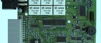
Purpose of parts on the board of the Priora electrical package control unit 2170-3763040
F1 (green) 30 Electronic engine management system F2 (blue) 60 power package control unit, engine fan, heated rear window, ignition switch relief relay F3 (blue) 60 cooling fan power supply circuit, horn, alarm, ignition switch, combination devices, interior lighting, brake light, cigarette lighter F4 (blue) 60 Generator Priors F5 (red) 50 Electromechanical power steering F6 (blue) 60 Generator
Fuse box of Lada Priora in the cabin
F1 (blue) 15 Main relay and starter interlock circuit F2 (brown) 7.5 Controller power circuit F3 (blue) 15 Electric fuel pump fuse K1 - Ignition relay K2 - Electric fuel pump relay
Lada Priora fuse box under the instrument panel
F1 25 Electric radiator fan of the cooling system F2 25 Heated rear window Priors F3 10 High beam right F4 10 High beam left F5 10 Sound signal F6 7.5 Low beam (left) F7 7.5 Low beam (right) F8 10 Alarm signal F9 25 Heater Priors F10) 7.5 Interior lighting, instrument cluster, brake light F11 20 Windshield wiper F12 10 Terminal 15 devices F13 15 Cigarette lighter F14 5 Left side light, license plate light, trunk light F15 5 Right side light F16 10 Terminal 15 ABS F17 10 Fog light (PTF) left F18 10 Fog light (PTF) right F19 15 Heated seats F31 or F27 30 Electrical package control unit
At the end of the work, all the wires are successfully hidden behind the carpet and thermal insulation. Therefore, this type of work will not affect the visual appearance of the salon.
Electrical package control unit in Priora
The car electrical package controller is a unit responsible for the functionality of the car.
The node regulates the operation:
- electric window lifts;
- main panel backlight;
- functioning of turn signals;
- side and fog lights;
- rear lights;
- heated rear view window.
All these devices must work clearly and harmoniously. Since the safety of the driver and passengers during the trip largely depends on them.
Also, the control unit for the Priora electrical package adds additional convenience to the driver in driving the vehicle. Hence its running name “comfort block”.
TsBKE connectors
- XP1 connector - Molex 34729-0080
- XP2 connector - Molex 31372-1000
- connector X3 - Molex 34729-0200
- connector X4 - Molex 31372-1100
Comfort block functionality
The main functions that the comfort unit contains are electrical control in the car. Since the list of tasks performed is extensive. Malfunctions in the operation of the unit can seriously harm the driver, especially during dense traffic around the city.
Comfort block tasks:
- turn signal indication;
- car interior light;
- fog lamps, low beam lights, parking lights;
- electric double glazing unit;
- side mirrors operation, adjustment, heating;
- anti-theft mechanism;
- door blocking;
- security alarm;
- luggage compartment lighting;
- dashboard lighting.
Each of these functions is essential for a car. Therefore, excluding even one of them from work will bring significant inconvenience to the driver.
Purpose of CBKE
The TsBKE block is designed to perform the following functions
:
- alarm system;
- control of the windshield wiper in the “manual control” mode;
- control of the windshield wiper in the “automatic control” mode (for TsBKE 21900-3840080-20);
- windshield defroster control;
- control of the rear window heater and electric side mirror heaters;
- control of low beam headlights, side lights and daytime running lights in the “manual control” mode, provided for by UNECE Regulation No. 48-04;
- control of low beam headlights, side lights, daytime running lights in the “automatic control” mode (for TsBKE 21900-3840080-20);
- control of daytime running lights in accordance with UNECE Regulation No. 48-04;
- high beam headlight control;
- control of direction indicator and hazard warning lamps;
- interior lamp control;
- energy saving control of vehicle interior lighting devices;
- central locking: locking/unlocking the side door locks from the key, from the driver's door lock button from the passenger compartment, from the button in the driver's door module;
- opening the trunk lid (tailgate) from a button in the cabin;
- control of electric window lifters;
- remote control;
- control of electric drives of side mirrors (for TsBKE 21900-3840080-20);
- front seat heating control;
- indication;
- trunk lighting control (for TsBKE 21900-3840080-20)
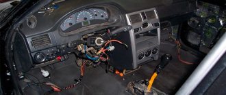
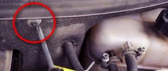
Location of the comfort block in Priora
In order to get to the comfort unit, you need to remove the plastic cover of the central panel of the machine. It is located between the driver and passenger seats, to the right of the gas pedal behind the bottom of the partition.
Voltage is supplied to the control unit through the main connector. And the secondary connector is responsible for performing functions.
The unit is protected by a casing from the penetration of moisture, dust and foreign bodies. The board itself is a set that holds 15 chips. Each chip is responsible for its own function, such as adjusting mirrors, power windows or opening doors.
To access the comfort block, you need a Phillips screwdriver and a 10mm wrench. After disconnecting the connectors, you need to remove the bolt and nut and remove the block itself.
Glass closer Pandora DWM
Connection diagram for the passenger door button in series through a duplicate button on the driver's door. Contacts 1-6 and 7-3 are always normally closed. When you press the up button, contacts 1-6 open and 1-2 close (window rises). When you press the down button, contacts 7-3 open and 7-2 closes (window down). The 30th contact of a 5-pin relay, without supplying voltage to the winding contacts, is constantly shorted to contact 88, which gives us the necessary negative contact (works like a switch). If voltage is applied to the winding, then contact 30 is disconnected from contact 88 and connected to contact 87. Contact 86 of the winding is connected to ground.
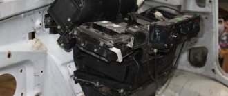
Location on newer models
Once you have disconnected the negative terminal from the battery and made the disassembly process safe. Disconnect the decorative protective cover located under the steering column. To do this, you need to release three mounting fasteners using a 10mm wrench.
In this case, the comfort block is located behind the mounting block. And you will have to act by touch, which is what car mechanics are used to doing.
Before removing the unit, you need to disconnect the three electrical harnesses from the wires. The fastening mechanisms should not be unscrewed completely. But only turn it 3 or more turns, since they have an open circuit. Then you can remove the block itself.
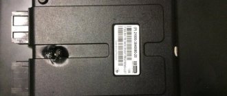
Classification of CBKE
Types of CBKE, features and their interchangeability
:
- 21900-3840080-20 Priora 2, Granta, Kalina 2 (in luxury trim levels), Datsun Ondo (Dream 1-2)
- 21900-3840080-10 Priora 2, Granta, Kalina 2 (in standard configurations)
- 21900-3840080-11 Priora 2 in the Standard configuration. Until 2016, Priora 2 was installed in the standard configuration
- 21900-3840080-21 Priora 2 in the Lux configuration early (2014-2015), not installed on the Norma, but will fit
- 21900-3840080-15 Priora 2 in Standard configuration, Kalina 2, Granta in Comfort configuration
- 21900-3840080-30 Datsun Mido in the Trust 1-3 configuration until 2015
- 21900-3840080-40 Datsun Mido in Dream 1, Dream 2 trim levels until 2015
- 21900-3840080-50 new block to replace 21900-3840080-10 (does not burn out)
- 21900-3840080-60 new block to replace 21900-3840080-20 (does not burn out)
- 8450100527 Grant from 2022
- 8450100534 Kalina 2 from 2022
- 8450100535 Datsun Ondo from 2022
- 8450100536 Datsun Mido from 2022 (Trust 1-3, Dream 1-2)
- 8450101126 Granta FL in the Classic, Optima and Comfort trim levels exclusively in cars with AMT (to implement the creeping AMT 2.0 mode, a door open signal is needed in the CAN bus, so it was necessary to introduce TsBKE)
- 8450101145 Granta FL in Luxe package
Buy
The TsBKE block is available in our online store (ask about availability in the comments).
Electrical unit pinout
The elements included in the electrical unit package are divided into the following components:
- drivers, each of which has its own function and is responsible for a separate section;
- relay coordination;
- transponder receiver;
- the transceiver is involved in the connection with the door module;
- two connectors for transmitting electricity and necessary engineering information.
When familiarizing yourself in detail with the diagram of the distribution of wires by numbers (pinouts). Working with the Priora comfort unit will not be particularly difficult.
Each contact in the diagram is described separately, which is important for understanding all operational problems. The Lada Priora comfort block diagram is present in the technical manual for the car.
Download pdf
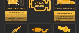
How to enable self-diagnosis of the instrument panel
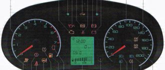
On-board computer staff Priora matrix instead of a clock in the console from the Lada Priora Using the panel you can “dig into the brains” of the Priora:
- Hold the button under the fuel gauge and turn on the ignition. The display should indicate the start of the test.
- Press the button again. The display should show the operating system version.
- Click again. The system should show error codes:
- (2) – High voltage level;
- (3) – DT malfunction;
- (4) – DTOZH malfunction;
- (5) – DTV malfunction;
- (6) – Motor overheating;
- (7) – Low oil level;
- (8) – Malfunction of the brake system;
- (9) – Battery discharge;
- E – Brain error, EEPROM.
- If necessary, reset the error: hold the button for three seconds.
- Release the button. Click again. All indicators should light up.
- Leave all the buttons. After 30 seconds, the self-test will automatically complete.
The dashboard contains the following parts, without which the car would not function:
- external lighting controller;
- switch for turning and lighting headlights;
- signal regulator;
- instrument cluster;
- wiper regulator.
Malfunctions in the operation of the comfort unit, how to eliminate them
- The turn signals do not light up. First, you should check the continuity of the fuse, lamps and steering column switch. If there is simply no contact somewhere, then the problem can be resolved very simply by resoldering the microcontacts. If there is a fault in the board itself and soldering the contacts does not help, then the controller should be replaced.
- The power window module or central locking does not work. This problem can also occur due to oxidation of the wires. Before removing the comfort unit, you need to check all the wires with a multimeter under the insulation in the control unit, which is built into the driver's door. If only one glass unit is faulty, the wires could become disconnected due to a broken contact.
After checking the wires, if the problem cannot be found. The DA7VN5016A or DA6VN5016A controller should be re-soldered. One of them is responsible for the double-glazed windows and the lock on the right door. The second mirrors the same functions, but on the left side.
The relay that sends information to the lifts is contained in the DA11L9848 controller. Often errors can be present here. Everywhere in the block at the outputs the numbering of wires is clearly written for correct connection.
Sometimes window lifters only work to lower the windows, but raising them is not available (or vice versa). To do this, check the connection so that all the pros and cons are in place.
Errors occur in the comfort unit when the window lift button to raise the window works to lower the window. With different polarities, when the glass rises instead of lowering, you need to change the connection of two adjacent wires.
- It happens that many problems arise at the same time. The fog lights, side lights, rear lights, heated rear glass, and interior light stop working. In this case, it is obvious that the problem comes from the comfort unit and the DA1 MC33972EW variant is re-soldered. If this does not help, then the entire circuit should be replaced.
- In case of failure of the rear fog lights and instrument lighting in the cabin, the DA9 VND5025AK component is re-soldered. And, as was the case with previous breakdowns. If this does not bring results, the entire scheme is changed.
- The central locking locks begin to operate when the power window keys are pressed. If replacing the comfort unit from another car does not bring any effect, then the essence of this breakdown is in the wiring. To do this, you need to carefully check the integrity of all wires leading to the comfort unit.
Possible causes of malfunctions
Before purchasing a new comfort unit, you need to try to eliminate any malfunction. In order not to make additional costs, because the comfort unit is quite expensive. Often the problem is simply a lack of contact due to aging or chafing of the wires.
Sometimes the comfort unit controllers can burn out, for this you need to inspect them visually or even check them using your sense of smell.
The most common complaints regarding the operation of the comfort unit are the failure of double-glazed windows, turn signals or dimensions.
All problems can occur due to the following events
- break on the W-Line communication line;
- combustion of regulation drivers;
- burnout of controllers responsible for the desired area;
- transponder malfunction;
- burnout or oxidation of contacts.
Before carrying out repair work, to comply with safety precautions, do not forget to disconnect the negative terminal from the battery.
Basket
Double-glazed window control unit “Norma” 1118 – 6512010 for VAZ 11183 “Kalina”
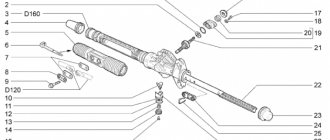
Aktuator On cars of the Kalina family, 2 types of non-interchangeable (by wiring) glass unit control controller 1118 - 6512010 and 11180 - 3763040 can be installed. 1118 – 6512010 has one 25-pin connection connector, 1118 – 3763040 (1118 – 3763040 – 10) – two connectors.
Remote control system for double-glazed windows “norm” on a VAZ 11183, Kalina. Controls power windows and central door locking. When the connector is removed, the engine does not start; the device performs some of the anti-theft functions.
Connection
| № | Wire color | Purpose, addressing |
| 1 |
External Shock or Volume Sensor Input (Not Used)* 2 Pink/Black To Door Lock Switch in Switch Box
3 Brown/Green K‑Line. To Kl. 71 ECM, Cl. 18 APS‑6
4 Brown Connects to ground when the driver's door is closed
5 Gray To heated rear window element
6 Black Mass
7 Pink/White To door lock switch in switch block
8 Yellow/Blue To the instrument cluster, to the APS‑6 indicator
9 Black/White Connects to ground when the hood is opened. C VK engine compartment lamp
10 Two White/Red Connects to ground when opening the rear doors
11 Brown/Red Connects to ground when opening the right front door
12 Output 12 V power supply for external sensor (Not used)*
13
Not used
14 Yellow Pulse + 12 V, closing all doors and trunk
15 Red/Blue K class. 14 APS‑6
16 Blue with Black To left direction indicator
17 Red/Blue Pulse + 12 V, opening passenger doors
18 Red/Black Pulse + 12 V, driver door open
19 Pink/Red Impulse + 12 V, opening the trunk lock
20 Yellow/Blue To terminal “15”, via fuse F 9, in the mounting block
21 Grey/Black “-” Horn relay
22 White/Blue Connects to ground when the driver's door is opened
23 Red To permanent plus through fuse F 5, in the mounting block
24 Blue To right turn signal
25 White/Black Connected to ground when opening the trunk
* A regular shock sensor from any alarm system (Alligator, Saturn, Clifford, APS) is suitable.
+ 12 V connect to pin 12; body – on the 6th; We connect the signal wire (a ground appears on it at the moment of activity) to the 1st contact.
During normal arming, Kalina now reacts to an impact on the body (it sounds a horn and blinks turn signals). Similarly, instead of a shock sensor, you can connect a volume sensor (for example, single-level MMS‑1).
You can also connect a pager: + 12 V of the pager transmitter on pin 12, minus on pin 21.
Double-glazed window control unit 1118 – 3763040 (- 10 ) for VAZ 11183 “Kalina”
| Controller board | ||
| Controller board |
| The key code is not readable |
1 . 1 Malfunction in the VZ communication coil circuit
1 . 2 Malfunction in the circuit from the block to the communication coil to the APS ECU
1 . 3 Transponder missing in OK
1 . 4 The transponder in OK is faulty (detected during pre-production preparation)
1 . 5 The transponder in the Republic of Kazakhstan is faulty (detected during pre-production preparation)
1 . 6 Malfunction of the input transponder circuit in the APS ECU
1 . 8 The communication coil came off from the VZ pad on the inside
1 . 1 - replacement 1118 – 6105006 (set) - rearrange the transponder - rearrange the remote control 1. 2 - replacing the instrument panel harness 1. 3 -replacement of KSUD -replacement of 1118 – 6105006 (set) -replacement of remote control -train the system 1. 4 - rearrange the transponder (if there is a clean one) otherwise: - replace 1118 – 6105006 (set) - retrain the system 1. 5 - replace the remote control - train the system 1. 6 - replace the faulty unit - train the system 1. 7 - replace the remote control with a “clean” one - train the system 1. 8 - replace 1118 – 6105006 (set) - rearrange the transponder - rearrange the remote control
What kind of engine does the Lada X-Ray have?
2. 1 Check the continuity of the circuit 2. 2 Trial one-by-one replacement of blocks with known good ones 2. 3 1. Check V on KSUD: room No. 12; room No. 13; room No. 44 and room No. 63 2. Check V on the APS: room No. 6; room No. 16; room No. 20 2. 4 Remove the block from the “Norma”, if the fault has disappeared and the internal combustion engine starts, then the electrical package is faulty. Carry out a test replacement of the “Norma” electrical package 2. 5 Check that the coolant is getting into the KSUD (Kalina) 3 sound signals IC flashes 3 . 1 APS ECU – “alien” 3. 2 OK – “foreign” 4 beeps IC lights up constantly The system is not trained - train the system
The KSUD was previously trained with another system. Very rare reason: the IS is blinking, there are no sound signals. The APS is trained, but the KSUD is “clean” - retrain the system
Abbreviations: IS – status indicator; VZ – ignition switch; OK – training key; RK – working key; RC – remote control; KSUD – engine control system controller; ECU - electronic control unit
Repair and replacement of the comfort unit
To begin repair work, you should make sure that the problem with the malfunction lies specifically in the electrical unit of the car. Alternatively, you can install a working unit in the machine and check the correct functioning of the problematic paths.
If with the new block all functions of the machine work without malfunctions, then the problem lies in the block. Before removal, check the integrity of the wires and fuses. And only then does work begin with the comfort block according to the following algorithm.
- install the car on the handbrake;
- for safety, disconnect the negative terminal;
- for the comfort of repair work, move the front seats back to free up the necessary space;
- remove the fasteners and remove the side casing;
- the fastening nuts are removed using a 10mm wrench;
- The block should be removed carefully, without damaging it on the casing walls or other elements. The two connectors (power and information) available in the block should be disconnected one by one.
A new one is installed in place of the faulty unit. In case of repair of the unit (such as re-soldering of individual controllers), it is installed in place after completion of the repair work. To carry out resoldering, the protective housing of the comfort unit is removed.
If you are installing a new unit, keep the purchase receipts until it is fully tested and in working condition so that you can return it in case of a possible malfunction.
For convenience, the unit is equipped with multi-colored wires to simplify the work of disconnecting and connecting. When weaving from the comfort block to the door, all wires must match in color.
After you have repaired the unit and connected it, you should check the operation of the windows, mirrors, lights, etc., then hide the wiring behind the car panels.
At the end of the work, all the wires are successfully hidden behind the carpet and thermal insulation. Therefore, this type of work will not affect the visual appearance of the salon.
Passat B5 fuse diagram
A description of all the design elements of the mounting block is given in the table. Salon part:
| Number | What is he responsible for? |
| 1 | Heated windshield washer nozzles |
| 2 | Power supply for turn signals |
| 3 | Control buttons for cruise control, climate control and steering wheel keys. |
| 4 | License plate light |
| 5 | Power supply, parking lights, navigation panel |
| 6 | Central locking and additional lamps |
| 7 | Speed sensor, ABS system, reversing lights |
| 8 | Phone power |
| 9 | Heated central locking and rear view mirrors |
| 10 | Headlight range control, standard radio |
| 11 | Automatic cruise control, power supply for tidy |
| 12 | Diagnostic devices |
| 13 | Feet |
| 14 | Interior lighting, anti-theft |
| 15 | Tidy, air conditioning and navigation controls. |
| 16 | ABS system power supply |
| 17 | Door lock heating power circuit |
| 18/19 | Driving lights |
| 20/21 | Low beam and headlight level control |
| 22/23 | Dimensions for each side respectively |
| 24 | Windshield wipers |
| 25 | Heater fan, air conditioner drive |
| 26 | Heated rear window power supply for exhaust recirculation system |
| 27 | Rear wiper |
| 28 | Fuel pump |
| 29 | ECM |
| 30 | Sunroof position drive |
| 31 | Cruise control, reverse gear and diagnostic connector output |
| 32 | ECM |
| 33 | Standard cigarette lighter |
| 34 | Injection and ignition control system |
| 35 | Tow hitch connector |
| 36 | PTF |
| 37 | Radio and telephone |
| 38 | Power supply for central locking, fuel tank lid opening drive, power windows |
| 39 | Emergency crew |
| 40 | Klaxon |
| 41 | ABS pump power supply or additional socket |
| 42 | Auxiliary cooling fan |
| 43 | S contact |
| 44 | Heated seats |
Separately, relay switches should be considered. In the R plane.
| Number | Description |
| 1 | Klaxon |
| 2 | Intermediate contact protection X |
| 3 | Wiper power supply |
| 4 | Fuel pump and glow plugs |
| 5/6 | Not used |
| 7/8 | Circuit breakers |
In the X plane.
| Number | Purpose |
| 1 | Radiator fan |
| 2 | Clutch |
| 3 | Air conditioning compressor magnetic clutch |
| 4 | Air conditioning power supply |
| 5 | Fuel pump for diesel engines |
| 6 | Interior lighting |
| 7 | Headlights |
| 8 | Glow plugs |
| 9 | Not used |
| 10 | PTF |
| 11 | On-board communication system |
| 12 | Starter power |
| 13 | Starter lock |
You also need to consider the power fuses mounted under the hood of the car.
| Number | Marking | Purpose |
| R1 | 167 | Engine control module |
| R2 | 373/100 | Secondary air intake pump |
| R3 | 429/219 or 53/411 | Power supply to the internal combustion engine control module or additional coolant pump |
| 1B | 116 | Injectors |
| 2B | Auxiliary coolant pump | |
| D | 130 | Secondary air pump |
| E | 115 | Plus ignition coils |
| F | 102 | ECU |
| G | 282 | Power plant electronics. |
Air conditioner fuse and relay
The system is divided into three parts. The power lines are powered from inserts 3 and 15 of the cabin unit. The control line runs from fusible protection No. 25.
Relay number 3 is responsible for the operation of the air conditioning compressor clutch and its direct activation. Relay number 4 is responsible for the remaining parts of the climate control.
Comfort block
The operation of the systems is controlled by fuse 38. In addition, it is supplied with No. 17.
Passat B5 cooling fan relay and fuse
The radiator fan is controlled by switch 1 of the cabin unit. This arrangement has remained unchanged since 1999.
Stove
Since 1995, the heater fuse has been installed in standard position 25. In some modifications, the installation location of the element may differ slightly.
Gasoline pump
The fuel fuse is mounted at position 28. The pump relay on gasoline and diesel engines is located in different places. Usually these are 4 and 5 respectively.
Finding a new relay will not be difficult. An article number is not required here - there are a large number of companies on the market that supply worthy analogues.
Passat B5 wiper fuse and relay: where are they located?
Windshield wiper repairs will need to begin by checking the corresponding inserts mounted at positions 24 and 27 for the front and rear of the car.
Starter fuse and relay
Since 1998, it has been installed at position 12. The standard arrangement is quite well thought out - the locking lever is mounted at number 13. Replacement of elements is required in case of their failure and is simple. The only snag is when the retractor needs to be serviced. The unit is mounted in the starter and to replace it you will need to disassemble the unit.
Cigarette lighter fuse
Passes through element 33 in the cabin. Since 2005, the manufacturer has also installed a rear cigarette lighter on cars. The unit also passes through the specified insert. Some users transfer elements or output them separately, trying to minimize the likelihood of breakdown when connecting powerful consumers.
Radio tape recorder
Standard acoustics are powered by fuse 10. When installing a more efficient system, the elements are often moved or installed separately. At the same time, music is connected directly from the battery.
Turn signals
The fuse is installed at position 39 in the on-board circuit. The switch is mounted separately and placed under the instrument panel. The average price ranges from 50 to 70 rubles.
Main relay Passat B5: where is it located
Installed in the engine compartment of the car. This arrangement has been relevant on B5 versions since 1995. The ignition coil is mounted slightly above the ECU.
Sound signal
The horn protective control element is installed at position 40. The relay is mounted at the first position in the block.
Window lifters
They are part of the on-board comfort system. You need to look for protective elements in points number 38.
Climate control
In most modifications of the machine there is no installation. The air conditioner takes its place and fully copes with its responsibilities.
VW Passat B5: glow plug relay
Located at number 8 in the interior relay panel.
Relay voltage regulator
Situated near the generator. This location is due to the design of the vehicle's electronic systems.
Trunk lock
Fuse 38 is responsible for the specified element, and also protects several related systems.
Backlight
No. 14 is responsible for interior lighting. Next, the system is protected by switch 6.
Wiper
The front and rear of the machine are protected by 24/27 fuse links respectively. There is only one relay here - No. 3.
Low beam
Power is supplied from fuses 20 and 21.
High beam
The system is also energy demanding. Each headlight is similarly powered by different fuses. Here these are inserts 18 and 19 for the left and right sides of the machine.
ABS
Due to the complexity of the design and the large amount of equipment, the ABS device units are powered directly from three fuses 7, 16 and 41.
Fog lights
Standard flashlights are powered by fuse 36, and both sides of the car are supplied at once. There is only one number 10 here.
Luke
Since 1997, this option began to be installed en masse on cars. In most configurations, insert 30 is responsible for the operation of the mechanism for opening and closing the panel.
Washer
The standard version is powered by part of the mounting block numbered 1. In modifications after 2001, the arrangement of the elements may differ slightly.
Dimensions
The lights are protected by inserts 22 and 23 for the left and right sides of the car. There is no relay here.
Charger
More interesting is the system for monitoring and limiting battery charging. All the necessary elements are placed on the wing of the vehicle, which allows minimizing the effort during their repair and maintenance.
Repairing the comfort unit on Priora yourself
If you did not have the skills to work with a soldering iron and similar electrical circuits before this repair. The best solution would be to forward this problem to an electrician at a service station. This type of work is labor-intensive and requires certain skills.
If you have already encountered similar problems and have experience in such work, then replacing these microcircuits is often done by car enthusiasts themselves. With the presence of a programmer, the data of some of the circuits can be re-registered, but this is a technically more complex process.
When using the master key, the control unit may go into emergency mode and the unit may be locked. For this type of work, you need to reset the control unit and erase errors.
Correct conditions for using the comfort block
Often, the breakdown can be determined immediately. Simply by performing an external inspection of the comfort unit. You can visually see contacts that have come loose due to mechanical damage or overheating.
For the structure to operate in normal mode, the operating range must correspond to the following parameters:
- mercury pressure – up to 800 mm;
- voltage range – 9-15 volts;
- permissible humidity in the cabin – up to 90%;
- the temperature in the cabin is from minus 45 to plus 40 degrees.