Headlights or the cigarette lighter suddenly stop working is a reason to open the mounting block and check the condition of the fuse or control relay. This article will tell you about the location of fuses in the Volkswagen Jetta VI (2010, 2011,2012, 2012, 2013, 2014, 2015, 2016, 2022, 2022, 2022 model years), their designations and location diagrams.
Description of the Volkswagen Jetta 6 fuse box
Fuses exist in even the simplest vehicles. They became necessary when electrical appliances and electrical wiring appeared. This element is the first to fail when the current level increases, thereby protecting expensive devices.
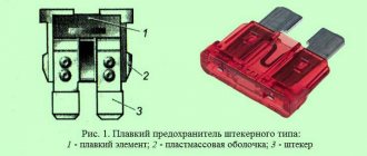
In cars, disposable fuses are used from a low-fusible element and a mechanism for attaching to contacts. These spare parts are located in the car both in the cabin and under the hood. There is a diagram of the protective parts of the Volkswagen Jetta 2013.
Location and diagram (for generation 2012 and 2013)
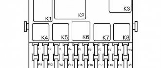
Protective devices and relays are united by a connecting unit, which is the fuse box. The operation of the car depends on the power supply circuits of the Volkswagen Jetta. The lights, fuel pump, and electric cooling fan motors enter the unit through a relay.
The fuse box plays a huge role for the stable functioning of the systems of the Volkswagen Jetta 2012,2013 models. The unit is located in the interior of the Volkswagen Jetta, on the left side of the instrument panel.
The upper shelf that is located there consists of a retaining screw, the lower instrument panel cover, the instrument panel and the cover that protects the fuse box. If the devices malfunction, you should look into the unit.
A device that is faulty will be immediately noticeable by its melted part and black coating.
Location and layout
Which method is better and safer?
Regardless of which method you choose to both disable and re-enable the Volkswagen Jetta headlight washer, each of them still has its own positive and negative aspects. So, for example, having solved your problem by removing the fuse, an error will be constantly recorded.
The decision is up to you!
In the case of a software approach, not only is an adapter required, which is quite expensive, but without it, the reverse steps cannot be performed and the headlight washer function on the Volkswagen Jetta cannot be connected back. Therefore, before using the second option, it is better to think several times.
Although in general, both methods are quite acceptable options for competently and independently approaching the question of how necessary the washer function is and how to disable it yourself. Thus, each Volkswagen Jetta car owner, comparing the presented pros and cons of the methods, will choose for himself the most suitable solution to this problem.
Volkswagen Jetta 6 fuses
The 6th generation Volkswagen Jetta was produced from 2010 to 2016. Protection of the on-board electrical network and its components consists of relays and fuses. For ease of maintenance, they are assembled into several separate modules.
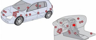
Fuse box locations
The 6th generation Volkswagen Jetta has two main fuse modules:
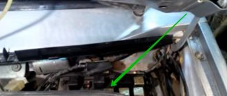
- Engine compartment unit - located in the engine compartment on the driver's side near the fender. To protect against dust and moisture, it is sealed with a sealed lid. It is secured on both sides with latches.
- Interior module - located on the driver's side at the bottom of the instrument panel under the headlight switch.
In addition to the main PCB units, the vehicle is equipped with several relay modules.
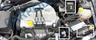
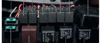
Underhood fuse module
The engine compartment PCB and relay unit has six relay slots and 37 fuse slots. Not all slots are used, some are additional.
Fuse layout in the motor module.
Protected electrical network or deviceNominal value, АColor marking Number on the diagram
| Relay connector | R1 | ||
| Relay connector | R2 | ||
| Relay connector | R3 | ||
| Relay connector | R4 | ||
| Relay connector | R5 | ||
| Relay connector | R6 | ||
| Not used | 1 | ||
| Engine control unit | 10.15 | Red Blue | 2 |
| Engine Radiator Fan Relay | 5 | Brown | 3 |
| ICE controller unit | 5, 10, 15 | Brown, red, blue | 4 |
| Backup fuse | 5, 10, 15 | Brown, red, blue | 5 |
| Backup fuse | 5, 10, 15 | Brown, red, blue | 6 |
| Engine controller | 5 20 | Brown, yellow | 7 |
| Engine controller | 10 | Red | 8 |
| Glow plug controller for diesel internal combustion engines, fuel pump relay | 5.15 | Brown, blue | 9 |
| Brake light breaker, speed sensor | 5 | Brown | 10 |
| Not used | 11 | ||
| Additional engine coolant pump | 5 20 | Brown, yellow | 12 |
| Main engine coolant pump | 5 | Brown | 13 |
| Engine start controller unit | 5 | Brown | 14 |
| On-board voltage controller | 30 | Green | 15 |
| Traction control system ESP, ABS system | 30 | Green | 16 |
| Automatic transmission | 30 | Green | 17 |
| Manual transmission | 20 | Yellow | 18 |
| On-board network controller switch | 1 | 19 | |
| Front wiper relay, +12V to windshield washer | 30 | Green | 20 |
| Air pumping motor into the intake manifold | 50 | Red | 21 |
| Not used | 22 | ||
| Traction control system ESP, ABS system | 40 | Green | 23 |
| Trailer electrical connection and power controller | 50 | Red | 24 |
| Electrical network of the ignition system, gasoline internal combustion engines | 50 | Red | 25 |
| Pre-heating plugs, diesel internal combustion engines | 60 | 26 | |
| Additional engine cooling radiator fan | 60 | 27 | |
| ECU, main engine controller | 40 | Green | 28 |
| ECU, main engine controller | 40 | Green | 29 |
| Additional on-board electrical circuits | 50 | Red | 30 |
| Standard audio amplifier | 30 | Green | 31 |
| Additional heating of coolant, Webasto | 40 | Green | 32 |
| Not used | 33 | ||
| Generator protection | 200 | 34 | |
| Not used | 35 | ||
| Electric power steering column | 80 | 36 | |
| Backup fuse | 80 | 37 |
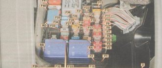
Internal fuse block
The interior fuse module does not have connectors for relays, but consists only of PCBs. It is quite compact and easy to maintain.
Protected electrical network or deviceNominal value, АColor marking Number on the diagram
| Not used | 1 | ||
| Steering wheel lock | 5, 7,5 | Brown | 2 |
| Instruments on the panel | 10 | Red | 3 |
| GSM phone antenna | 2 10 | Red | 4 |
| Rear fog lamp, left side | 7.5 | Brown | 5 |
| Multifunction controller | 10 | Red | 6 |
| Brightness of instruments and buttons, fog lamp relay, rear number plate illumination | 5 | Brown | 7 |
| Headlight washer system | 7.5 | Brown | 8 |
| Airbag system | 5 | Brown | 9 |
| Steering column switches, right side | 10 | Red | 10 |
| Not used | 11 | ||
| Not used | 12 | ||
| Complex fuse: | 5 | Brown | 13 |
| headlight range control controller; | |||
| rearview mirror; | |||
| mirror heating button; | |||
| light sensor; | |||
| parking sensors; | |||
| mirror adjustment; | |||
| climate control; | |||
| heated washer; | |||
| TPMS button; | |||
| Start/Stop system | |||
| Diagnostic bus, steering column switch left side, fuel pump controller unit, towed trailer recognition system, inverter-stabilizer 12V - 220V | 10 | Red | 14 |
| Diagnostic connector, headlight range control, interior fan relay, instrument and button backlight adjustment, mass air flow sensor | 10 | Red | 15 |
| Relay for additional engine cooling pump | 10 | Red | 16 |
| Standard alarm | 10 | Red | 17 |
| Headlight, left | 15 | Blue | 18 |
| Headlight, right | 15 | Blue | 19 |
| Additional heater antenna, starter interlock, automatic transmission selector, climate control, automatic transmission controller | 10 | Red | 20 |
| On-board power supply controller, two-tone horn | 15 20 | Blue yellow | 21 |
| OEM alarm bell, ignition breaker, OEM relay, cabin volume sensor, converter controller | 7,5 20 | Brown, yellow | 22 |
| Compass, rain, light sensor, interior lighting switch, on-board network controller | 10 | Red | 23 |
| Headlight range control controller with adaptive lighting | 10 | Red | 24 |
| checkpoint | 15 | Blue | 25 |
| Brake booster pump | 15 | Blue | 26 |
| Airbag system | 1 | 27 | |
| Additional coolant heating | 40 | Orange | 28 |
| Multifunction controller | 1 | 29 | |
| Cigarette lighter | 20 | Yellow | 30 |
| Backlight button, front | 30 | Green | 31 |
| Backlight switch, rear | 20 | Yellow | 32 |
| Interior fan speed adjustment, auxiliary heater adjustment, climate control controller | 40 | Orange | 33 |
| Left and right headlight bulbs, high beam | 15 | Blue | 34 |
| Steering column controller, horn | 10 | Red | 35 |
| Multifunction controller | 25 | 36 | |
| Daytime running lights, left side | 15 | Blue | 37 |
| Daytime running lights, right side | 15 | Blue | 38 |
| Low beam bulbs, left and right | 20 | Yellow | 39 |
| Trailer on-board electrical controller | 15 | Blue | 40 |
| Trailer on-board electrical controller | 15 | Blue | 41 |
| Trailer on-board electrical controller | 20 | Yellow | 42 |
| Rear right door electrical module | 30 | Green | 43 |
| Rear window heating, heating relay | 30 | Green | 44 |
| Front door electrical module | 30 | Green | 45 |
| Rear left door electrical module | 30 | Green | 46 |
| Gasoline pump, booster pump for diesel internal combustion engines | 15 | Blue | 47 |
| Multifunction controller | 20 | Yellow | 48 |
| Climate control | 40 | Orange | 49 |
| Heated driver and passenger seats | 30 | Green | 50 |
| Power sunroof | 20 | Yellow | 51 |
| Klaxon | 20 | Yellow | 52 |
| Heated rear passenger seats | 15 | Blue | 53 |
| Rear fog lights | 15 | Blue | 54 |
| Interior and trunk light switch | 20 | Yellow | 55 |
| Not used | 56 | ||
| GPS navigator, audio preparation | 15 20 | Blue yellow | 57 |
| Connecting additional devices | 30 | Green | 58 |
| Standard audio amplifier | 30 | Green | 59 |
| Coolant heating | 30 | Green | 60 |
Volkswagen Jetta 5 fuses
To prevent damage to electrical appliances or on-board network circuits, the 5th generation Volkswagen Jetta, produced from 2005 to 2010, uses fuses and fuses. They are located in modular blocks together with relays.
Where are the fuse boxes located?
In the VolksWagen Jetta 5, the manufacturer assembled all the fuses into two blocks:
- Engine block - located in the engine compartment, on the driver's side, next to the expansion tank for brake fluid.
- Cabin module - located on the side of the dashboard on the driver's side.
Underhood fuse module
To access the motor fuse and relay module, you need to move the fixing elements of the cover in the direction of travel of the car and remove it. After checking and replacing the PP, it is necessary to replace the cover, return the latches to their original position and make sure that the unit is sealed.
Layout of fusible elements in the motor module.
Protected circuit or electrical equipment Rating, A Color marking No.
| Connector not used | 1 | ||
| Steering Column Switches | 5 | Light yellow | 2 |
| OBDII connector for diagnostics | 5 | Light yellow | 3 |
| ABS system unit, electronic components | 30 | Light green | 4 |
| Automatic transmission controller | 15 | Blue | 5 |
| Instruments on the panel | 5 | Light yellow | 6 |
| Connector not used | 7 | ||
| Radio in the center console | 15 | Blue | 8 |
| GSM phone | 5 | Light yellow | 9 |
| Engine controller, relay | 5 | Light yellow | 10 |
| Cabin heater fan controller, auxiliary heater controller | 20 | Yellow | 11 |
| OBDII diagnostic bus controller | 5 | Light yellow | 12 |
| ECU, engine controller | 15 | Blue | 13 |
| Relay +12V on-board power supply | 20 | Yellow | 14 |
| Exhaust oxygen sensor, fuel pump, glow plugs diesel internal combustion engine | 15 | Blue | 15 |
| ABS system unit, electronic components | 30 | Light green | 16 |
| Klaxon | 15 | Blue | 17 |
| Standard audio amplifier | 30 | Light green | 18 |
| Front windshield wipers | 30 | Light green | 19 |
| Connector not used | 20 | ||
| +12V lambda probe heating | 15 | Blue | 21 |
| Brake pedal breaker, clutch pedal breaker | 5 | Light yellow | 22 |
| Intake Manifold Air Recirculation Pump, High Pressure Fuel Pump, Mass Air Flow Sensor (MAF) | 10 | Red | 23 |
| EGR valve | 10 | Red | 24 |
| Front headlight, right side | 30 | Light green | 25 |
| Front headlight, left side | 30 | Light green | 26 |
| Intake manifold air recirculation pump, engine warm-up mode | 40 | Orange | 27 |
| Engine starter relay | 40 | Orange | 28 |
| +12V on pin 30 | 40 | Orange | 29 |
| Contact X | 40 | Orange | 30 |
| Auxiliary cooling fan motor relay | R1 | ||
| Automatic transmission controller relay | R2 |
Cabin module of fusible elements
To access the fuses of the cabin module in a 5th generation Volkswagen Jetta, you need to open and lock the driver's door. On the side of the dashboard there is a safety block cover. To open it, you need to pry the outer edge with a screwdriver and pull it towards you.
Pinout of PP interior block
Protected circuit or electrical equipment Rating, A Color marking No.
| Connector not used | 1 | ||
| Steering Column Switches | 5 | Light yellow | 2 |
| OBDII connector for diagnostics | 5 | Light yellow | 3 |
| ABS system unit, electronic components | 30 | Light green | 4 |
| Automatic transmission controller | 15 | Blue | 5 |
| Instruments on the panel | 5 | Light yellow | 6 |
| Connector not used | 7 | ||
| Radio in the center console | 15 | Blue | 8 |
| GSM phone | 5 | Light yellow | 9 |
| Engine controller, relay | 5 | Light yellow | 10 |
| Cabin heater fan controller, auxiliary heater controller | 20 | Yellow | 11 |
| OBDII diagnostic bus controller | 5 | Light yellow | 12 |
| ECU, engine controller | 15 | Blue | 13 |
| Relay +12V on-board power supply | 20 | Yellow | 14 |
| Exhaust oxygen sensor, fuel pump, glow plugs diesel internal combustion engine | 15 | Blue | 15 |
| ABS system unit, electronic components | 30 | Light green | 16 |
| Klaxon | 15 | Blue | 17 |
| Standard audio amplifier | 30 | Light green | 18 |
| Front windshield wipers | 30 | Light green | 19 |
| Connector not used | 20 | ||
| +12V lambda probe heating | 15 | Blue | 21 |
| Brake pedal breaker, clutch pedal breaker | 5 | Light yellow | 22 |
| Intake Manifold Air Recirculation Pump, High Pressure Fuel Pump, Mass Air Flow Sensor (MAF) | 10 | Red | 23 |
| EGR valve | 10 | Red | 24 |
| Front headlight, right side | 30 | Light green | 25 |
| Front headlight, left side | 30 | Light green | 26 |
| Intake manifold air recirculation pump, engine warm-up mode | 40 | Orange | 27 |
| Engine starter relay | 40 | Orange | 28 |
| +12V on pin 30 | 40 | Orange | 29 |
| Contact X | 40 | Orange | 30 |
| Auxiliary cooling fan motor relay | R1 | ||
| Automatic transmission controller relay | R2 |
In the engine compartment
1) To access the fuses and the relay-mounting block located in the engine compartment, open the hood.2) Slide the cover fastening latches forward...3) and remove the cover.
Fuses and relays in the mounting block located in the engine compartment
Assignment of fuses/relays in the engine compartment mounting block
| Number | Current, A | Protected circuit |
| 1 | 30 | Front and right rear turn signal lamps, right brake lamp, front and right rear parking lamps, right reversing lamp, right low and high beam lamps, right fog lamp |
| 2 | 15 | Sound signal |
| 3 | 40 | Air pump |
| 4 | Reserve | |
| 5 | 50 | Main fuse |
| 6 | 50 | Ignition switch power circuit unloading relay |
| 7 | Reserve | |
| 8 | 30 | Windshield wiper motor |
| 9 | Right tail light lamp | |
| 10 | 15 | Oxygen concentration sensor |
| 11 | 5 | Brake light switch |
| 12 | 5 | Intake geometry variable valve |
| 13 | 10 | Air pump relay, power supply injector |
| 14 | 30 | Windshield wiper motor |
| 15 | 30 | Mechatronic unit for robotic gearbox |
| 16 | 5 | Interior equipment control unit |
| 17 | 20 | ABS control unit |
| 18 | 15 | Mechatronic unit for robotic gearbox |
| 19 | 5 | Instrument cluster |
| 20 | 40 | Ignition switch positive terminal relay |
| 21 | 15 | Audio head unit |
| 22 | 40 | ABS control unit, electric module pump |
| 23 | 30 | Front and left rear turn signal lamps, left brake lamp, front and left rear parking lamps, left reversing lamp, left low and high beam lamps, left fog lamp |
| 24 | Reserve | |
| 25 | 5 | Diagnostic connector |
| 26 | 15 | ECU |
| 27 | 20 | Fuel pump, ignition coil |
| 28 | 10 | Control oxygen concentration sensor |
| 29 | 5 | Telephone communication device (optional) |
| 30 | 10 | ECU |
| R1 | Air pump relay | |
| R2 | ECU power relay |
