· 1 – head unit fuse (20 A),
· 2, 23 - ventilation and heating system fuses (7.5 A and 30/40 A),
· 3 — hatch fuse (20 A),
5 - fuse for the door electrical control unit (7.5 A),
6 - brake light fuse (7.5 A),
· 7 — fuse for the interior electrical equipment control unit (30 A),
8 - fuse for the passenger door electrical control unit (7.5 A),
9 - fuse of the central control device (7.5 A),
10 - control unit fuse on the steering column (7.5 A),
· 11 — diagnostic connector fuse (5 A),
· 12 — battery protection device fuse (7.5 A),
15 - fuse for the driver's door electrical control unit (30 A),
· 17, 26 — instrument cluster fuses (15 A and 7.5 A),
· 18 - air conditioner fuse (7.5 A),
20 - ESP sensor fuse (7.5 A),
· 21 – telematics fuse (7.5 A),
· 22 — cigarette lighter fuse (30 A),
· 25 - heating/air conditioning system fuse (7.5 A).
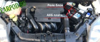
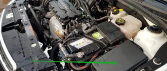
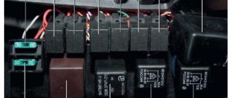
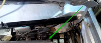
In the engine compartment
All three blocks of the engine compartment are located near the battery. They are marked in the picture above.
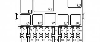
Diagram of elements of motor block No. 1
| № | Purpose |
| 11a | (F59) Engine control fuse |
| 11b | (F56) Fuel heater fuse |
| 10 | Exhaust air pump relay |
| 12 | Fuel heater relay |
| 13 | Headlight washer delay relay |
| 14 | Spare |
| 15 | |
| 16,17 18,19 | glow plug relay |
Opel Vectra B engine block relay diagram No. 2
| № | Purpose |
| 1 | A/C compressor clutch relay |
| 2 | Cooling fan relay |
| 3 | Cooling fan timer. |
| 4 | Cooling fan relay |
| 5 | |
| 6 | |
Diagram of elements of motor block No. 3
| Option 1 | |
| № | Purpose |
| 1 | cooling fan |
| 2 | Compressor |
| 3 | cooling fan |
| 4 | |
| Option 2 | |
| № | Purpose |
| 7 | Cooling fan |
| 8 | |
| 9a | Cooling fan fuse |
| 9b | |
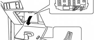
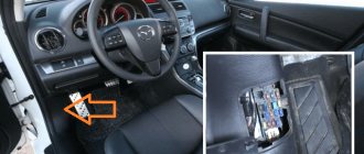
Location of the block and purpose of fuses
The main mounting block of the Opel Grandland https://nizhegorodec.opel.ru/avtomobili/mashiny/grandland-x-my18/index/ B is located in the cabin under the dashboard. To access it, simply remove the protective cover to the left of the steering column. One fuse can protect one or more nodes in the same circuit of the same rating (current in amperes). For installation and connection of additional equipment, backup sockets and connectors for relays are provided.
Assignment of fuses in the mounting block
Fuse number on the block diagram Rated current (amps) Circuit of the protected electrical circuit
| 1 | — | reserve |
| 2 | 30A | Cooling fan drive, air conditioner power circuit |
| 3 | 40A | Heating element on the rear window |
| 4 | — | reserve |
| 5 | — | reserve |
| 6 | 10A | Headlight Level Controller, Low Beam Circuit |
| 7 | 10A | Rear right side light, tail lights |
| 8 | 10A | Right high beam headlight |
| 9 | 30A | Headlight washer drive |
| 10 | 20A | Steering column horn circuit |
| 11 | 30A | Central locking (locking) |
| 12 | 20A | Fog lights |
| 13 | — | reserve |
| 14 | 30A | Wiper blade drive |
| 15 | - the electrical circuit in the block is provided with sockets in the circuit of the same rating (current in amperes). | reserve |
| 16 | 10A | Rear fog light |
| 17 | 30A | Front window drive chain |
| 18 | 10A | License plate light |
| 19 | 20A | Fuel pump circuit |
| 20 | 30A | Rear window drive chain |
| 21 | — | reserve |
| 22 | 20A | Interior lighting circuit, dashboard lighting, radio, hazard warning lights |
| 23 | — | reserve |
| 24 | 10A | Left low beam headlight |
| 25 | 10A | Rear left side light |
| 26 | 10A | Left high beam headlight |
| 27 | — | reserve |
| 28 | — | reserve |
| 29 | 10A | Hazard warning lights, rear view mirror control drive |
| 30 | 30A | |
| 31 | — | reserve |
| 32 | — | reserve |
| 33 | 20A | Output to trailer connector |
| 34 | 20A | Audio auxiliary circuit |
| 35 | 10A | Transmission automatic transmission, ABS |
| 36 | 20A | Heated front seats |
| 37 | 10A | Cigarette lighter circuit in the cabin |
| 38 | 10A | Stop signal |
| 39 | 10A | Automatic transmission sensors |
| 40 | 10A | Fan drive on the radiator of the cooling system |
| 41 | 10A | Heated mirror circuit |
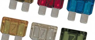
Each fuse is painted a specific color, which corresponds to the rated current:
- 10A – red
- 20A – yellow
- 30A – green
- 40A – orange
When replacing burnt-out fuse links with new ones, you can focus on the color if the markings on the connectors are missing or are difficult to access. The installation of temporary jumpers is not allowed - this leads to short circuits and failure of the remaining electrical equipment, and in a high-voltage circuit, the jumper can lead to a fire. The faulty fuse (fuse link) is removed from the socket with special tweezers, being careful not to damage the wiring. Tweezers are usually included with the mounting block and are located on the side or on any backup connector.
Replacing the Z22YH fuel pump from VAZ - logbook Opel Vectra Direct 2.2 l 155hp 2007 on DRIVE2
Hello, I would like to immediately thank you for the maximum assistance provided in helping with the fuel pump.
So! I started the car, waiting for it to warm up, like usual! But after 10 seconds the engine began to shake violently and stalled. I didn’t understand at first. What the hell... I turned on the ignition again and then I realized I couldn’t hear the pump
It’s already 21:00, the shops are all closed, and I’m standing on the other outskirts of the city, I had to take a bus home, I arrived home, abruptly went into Drive and then within 5 minutes they helped me, they wrote that the fuel pump would fit from a VAZ 2110. I called a friend and told him the situation, and in about 20 minutes he arrived with a new fuel pump from 10K, oh MIRACLE! I really didn’t want to leave the car on another part of the city! Let's go, disassemble and replace the pump one to one! No need to cut anything, 650 rubles and the car is running
I’ve been driving with this fuel pump for more than 10 days now and the conclusion is that this car really started to pick up speed more vigorously from 120 to 180 very quickly, taking into account that I don’t have a catalyst, but when accelerating from 120 km to 180 km there are very, very small jerks that are barely noticeable
Yes, I understand the fuel pump from the VAZ is 60 liters per hour, probably this is not enough and the fuel injection pump can be killed. Who knows how many liters per hour the original fuel pump pumps?
Diagnosis of a faulty electrical circuit
When working with a car's electrical circuit, you must turn off the ignition and battery by removing the minus terminal. The main causes of electrical equipment failures:
- Contact faults (oxidation) at connectors
- Open circuit in wiring sections
- Short circuits
- Unstable grounding (poor contact to ground)
- Relay failure or blown fuse
To diagnose a circuit, use a voltmeter or a 12V tester (you can use a simple probe with an indicator), an autonomous power source and a set of wires with alligator clips. First, check the safety of the fuses and the functionality of the relay - the fuse links are inspected visually, the relay should make a characteristic click when voltage is applied. If all fuses are good, then the problem is in the wiring.
Color marking
Let's start with color coding, which makes it possible to quickly determine the design parameters of fuses, indicated in amperes. These colors will be used in the future in all diagrams attached to the article.
Knowing the color coding greatly simplifies not only the search for faulty components, but also the selection of a replacement that is suitable for its characteristics.
Important! Do not install fuses whose parameters do not meet the requirements of the developers! This may cause serious malfunction or fire.
Fuses and relays
color="red"> Warning
Fuse ratings and electrical circuits may vary from year to year.
color=»red»> Fuse location
Fuses
| N | CURRENT STRENGTH (COLOR) | ELECTRICAL CIRCUIT |
| 1 | – | – |
| 2 | 30 (Green) | Air conditioning, cooling fan |
| 3 | 40 (Orange) | Rear window defroster |
| 4 | ||
| 5 | – | – |
| 6 | 10 (Red) | Low beam headlights, light corrector |
| 7 | 10 (Red) | Parking light, rear right side lights |
| 8 | 10 (Red) | Far right light |
| 9 | 30 (Green) | headlight washer |
| 10 | 20 (Yellow) | Sound signal |
| 11 | 30 (Green) | Central locking system |
| 12 | 20 (Yellow) | Fog lights |
| 13 | – | – |
| 14 | 30 (Green) | Wiper |
| 15 | – | – |
| 16 | 10 (Red) | Rear fog light |
| 17 | 30 (Green) | Window lifters |
| 18 | 10 (Red) | License plate light |
| 19 | 20 (Yellow) | Fuel pump |
| 20 | 30 (Green) | Window lifters |
| 21 | – | – |
| 22 | 20 (Yellow) | Hazard warning lights, information display, on-board computer, interior lighting, radiator fan, radio, signaling devices. |
| 23 | – | – |
| 24 | 10 (Red) | Low left beam, light corrector |
| 25 | 10 (Red) | Parking lights and rear left lamp |
| 26 | 10 (Red) | Far left light |
| 27 | – | – |
| 28 | – | Coolant heater (diesel) |
| 29 | 10 (Red) | Hazard warning lights, electrically controlled exterior mirrors, power windows, sunroof, cruise control, interior lighting |
| 30 | 30 (Green) | Luke |
| 31 | – | – |
| 32 | – | – |
| 33 | 20 (Yellow) | Terminal 30: Trailer DC current |
| 34 | 20 (Yellow) | CD changer switch |
| 35 | 10 (Red) | ABS, Traction Control, automatic transmission |
| 36 | 20 (Yellow) | Heated front seats |
| 37 | 10 (Red) | Cigarette lighter |
| 38 | 10 (Red) | Brake lamps, automatic transmission, display, cruise control |
| 39 | 10 (Red) | Automatic transmission |
| 40 | 10 (Red) | Radiator fan, rear window defroster |
| 41 | 10 (Red) | Mirror heater |
Location of the main fuse and relay box on the driver's side instrument panel
| The main fuse and relay box is located under a cover in the instrument panel on the driver's side. |
The location of fuses and relays is shown on the cover.
Each fuse has an inscription indicating the amount of current it allows.
| To remove the fuse, use tweezers to remove the fuse from the connector. Remove the fuse from the tweezers. The wire inside the fuse is easily visible and will be severed if the fuse blows. |
Always replace the fuse with another fuse of the same capacity. Never replace a fuse more than once without determining the cause of the blown fuse.
Relay
A relay is an electronically controlled switch that is typically used as follows:
– the relay can switch high voltage current remotely from the circuit in which this current flows, allowing the use of thinner wires and switch contacts; – a relay can have more than one control input, unlike a mechanical switch; – the relay can perform the function of a timer, for example, it issues an operating interval for the windshield wipers.
Relay location in front of the battery in the engine compartment
| The relays are located in the main fuse and relay box, although some engine related relays are located in the engine compartment. |
If a relay controlled system fails and the relay may be causing the problem, listen to the relay while the system is on. If the relay is working properly, you should hear a click when it turns on. If the relay is working properly, then the cause of the malfunction lies in the elements or connecting wires. If the relay does not work, it means that it is not receiving the main power supply or control pulse, or the relay is faulty.
Removing the relay
Relay and fuse layout diagrams for Opel Vectra generation B and C cars
Auto expert. Consultant for the site opelpro.ru.
Detecting faults in the electrical circuits of modern cars is not an easy task even for a trained professional. As for ordinary motorists, they may have problems even at the stage of searching for failed relays and blown fuses.
The main problems arise from a lack of information. This article, dedicated to Opel Vectra cars of generations B and C, will satisfy the existing hunger for information. Having studied it, car owners will have the opportunity to find out where the relays and fuses are located on their cars and what they are responsible for.
In order to make the information more visual, the article has been supplemented with detailed diagrams. Do not be mistaken in thinking that the schemes are being repeated due to an error by the authors. Depending on the specific year of production of the Opel Vectra and the configuration of the popular model, the components may be placed differently.
To avoid making mistakes, be patient and find exactly your version of the car. Well, are you ready? Then let's get started!
Designation of fuses and relays Opel Vectra
The table shows the fuse number, its factory color and current strength and the electrical circuit for which the fuse is responsible.
| N | CURRENT STRENGTH (COLOR) | ELECTRICAL CIRCUIT |
| 1 | – | – |
| 2 | 30 (Green) | Air conditioning, cooling fan |
| 3 | 40 (Orange) | Rear window defroster |
| 4 | ||
| 5 | – | – |
| 6 | 10 (Red) | Low beam headlights, light corrector |
| 7 | 10 (Red) | Parking light, rear right side lights |
| 8 | 10 (Red) | Far right light |
| 9 | 30 (Green) | headlight washer |
| 10 | 20 (Yellow) | Sound signal |
| 11 | 30 (Green) | Central locking system |
| 12 | 20 (Yellow) | Fog lights |
| 13 | – | – |
| 14 | 30 (Green) | Wiper |
| 15 | – | – |
| 16 | 10 (Red) | Rear fog light |
| 17 | 30 (Green) | Window lifters |
| 18 | 10 (Red) | License plate light |
| 19 | 20 (Yellow) | Fuel pump |
| 20 | 30 (Green) | Window lifters |
| 21 | – | – |
| 22 | 20 (Yellow) | Hazard warning lights, information display, on-board computer, interior lighting, radiator fan, radio, signaling devices. |
| 23 | – | – |
| 24 | 10 (Red) | Low left beam, light corrector |
| 25 | 10 (Red) | Parking lights and rear left lamp |
| 26 | 10 (Red) | Far left light |
| 27 | – | – |
| 28 | – | Coolant heater (diesel) |
| 29 | 10 (Red) | Hazard warning lights, electrically controlled exterior mirrors, power windows, sunroof, cruise control, interior lighting |
| 30 | 30 (Green) | Luke |
| 31 | – | – |
| 32 | – | – |
| 33 | 20 (Yellow) | Terminal 30: Trailer DC current |
| 34 | 20 (Yellow) | CD changer switch |
| 35 | 10 (Red) | ABS, Traction Control, automatic transmission |
| 36 | 20 (Yellow) | Heated front seats |
| 37 | 10 (Red) | Cigarette lighter |
| 38 | 10 (Red) | Brake lamps, automatic transmission, display, cruise control |
| 39 | 10 (Red) | Automatic transmission |
| 40 | 10 (Red) | Radiator fan, rear window defroster |
| 41 | 10 (Red) | Mirror heater |
Replacing the mesh in the gas tank) — logbook Opel Vectra Elegant Chereshnya 2001 on DRIVE2
Now we got around to the filter in the tank. and as it turned out, it was not in vain... the first time I did it, I was stumped for a long time... but I mustered up the courage and got to work...
I removed the rubber plug under the seat and saw a terrible picture...
I had to pick up a vacuum cleaner... then I removed the retaining ring using a hammer and some mother
Next, I had to remove the hoses from the tubes... then a surprise awaited me) there was still pressure left... I was covered in gasoline))) it’s good that there was a reaction and put it back on, took a Big, Big syringe... and began to slowly relieve the pressure and select gasoline with the syringe. Finally we remove the cover...
when I pulled out the fuel pump I saw an unpleasant picture... the screen was covered in trash... and a pile of garbage under the pump screen...
a bandage from my first aid kit came to the rescue)))
to repair a German car, you need German accessories)))
Having removed all the crap from the tank, I installed a new mesh))
Mileage: 204800 km
Block in the cabin
The main fuse and relay box is located under the instrument panel on the driver's side and is covered with a protective cover. On the reverse side of which the current diagram will be applied.
Description
| 1 | Jumper (License Plate Lights) |
| 2 | Horn relay |
| 3 | High beam relay |
| 4 | Rear window wiper motor relay |
| 5 | Heated mirror relay |
| 6 | Fog light relay |
| 7 | Rear fog lamp relay |
| 8 | Relay - turn signal switch |
| 9 | Windshield wiper motor relay |
| 10 | Rear window defroster relay |
| 11 | Heater Fan Motor Relay (with A/C) |
| 12 | Heater Fan Motor Relay (with A/C) |
| 13 | Air conditioner relay |
| 14 | Multifunction control unit |
| F1 | — |
| F2 | 30A Heater/air conditioner |
| F3 | 40A Rear window defroster |
| F4 | — |
| F5 | — |
| F6 | 10A/15A Headlight range control, right headlight - low beam |
| F7 | 10A Front right/rear right side lamps |
| F8 | 10A Right headlight - high beam |
| F9 | 30A Headlight washers |
| F10 | 20A Horn |
| F11 | 30A Central lock |
| F12 | 20A Fog lights |
| F13 | — |
| F14 | 30A Windshield wiper |
| F15 | 5A Interior lamps |
| F16 | 10A Rear fog light |
| F17 | 30A Electric window lift |
| F18 | 10A License plate lamp |
| F19 | 10A Audio system |
| F20 | 30A Electric window lift |
| F21 | 10A Audio system, central locking, hazard warning lights, automatic transmission selector lock solenoid valve (“P”) |
| F22 | 20A Air conditioning system, audio system, multifunction display, cooling fan motor, hazard warning lights, instrument cluster indicators |
| F23 | Reserve |
| F24 | 10A/15A Left headlight - low beam, headlight range control |
| F25 | 10A Front Left/Rear Left Side Lamps |
| F26 | 10A Left headlight - high beam |
| F27 | Reserve |
| F28 | 20A Coolant Heater (Diesel) |
| F29 | 10A Power door mirrors, power windows, low beam headlights, turn signals/hazard warning lights, interior lights, instrument cluster, instrument cluster indicators, reverse lights, sunroof |
| F30 | 30A Hatch |
| F31 | 5A Instrument cluster illumination |
| F32 | 10A Daytime Lighting Bulbs |
| F33 | 30A Trailer electrical connector |
| F34 | 10A Audio CD Changer |
| F35 | 10A Anti-lock braking system (ABS), automatic transmission control system, traction control system (TCS) |
| F36 | 20A Air conditioning, seat heaters |
| F37 | 10A Cigarette lighter |
| F38 | 10A Air conditioning system, cruise control, multifunction display, cooling fan motor, brake lights |
| F39 | 10A Automatic Transmission |
| F40 | 10A Air conditioning system, cooling fan motor |
| F41 | 10A Door mirror heater |
Fuse number 37 is responsible for the operation of the cigarette lighter.
Opel Vectra C
When creating the third generation of the popular model, the developers increased the number of electrical and electronic components used in the design of the car. As a result, the number of relays and fuses has increased. True, there has been some uniformity - this is a big plus.
Models 2002 – 2005
Block in luggage compartment
True for all modifications of the Opel Vectra C, produced from 2002 to 2005 (before restyling).
- Rear window cleaner.
- –.
- Heated rear left seat.
- Heated rear right seat.
- Anti-theft alarm sound.
- –.
- Central locking and fuel filler flap.
- –.
- Main ignition circuits.
- Heated rear window.
- Fuel pump.
- F1. –.
- F2. –.
- F3. Electric seat.
- F4. Heated rear window.
- F5. Electric seat.
- F6. Window lift drive.
- F7. Window lift drive.
- F8. Heated right rear seat.
- F9. Anti-theft system, sound signal.
- F10. Fuel pump.
- F11. Battery voltage, pin 30.
- F12. Heated left rear seat.
- F13. Trailer connection connector.
- F14. Rear window cleaner.
- F15. Heated left front seat.
- F16. Heated right front seat.
- F17. Seat ventilation.
- F18. –.
- F19. Dual audio system, multifunctional travel assistant kit.
- F20. –.
- F21. Anti-theft system.
- F22. Ultrasonic volume change sensor (anti-theft system).
- F23. Broken glass sensor (anti-theft system).
- F24. Battery voltage, pin 30.
- F25. –.
- F26. Multifunctional travel kit “Travel assistant”.
- F27. Air conditioning, tire pressure monitoring, rain sensors and presence of a passenger in the seat.
- F28. Parking system sensor.
- F29. –.
Blocks under the hood
In the engine compartment, next to the battery, there are 3 blocks with fuses and relays.
Check the purpose with your diagrams on the covers of the blocks.
Block 1
Scheme
Designation
- 10 — Exhaust air pump relay
- 12 — Relay fuel heater
- 13 — Headlight washer delay relay
- 14 - Reserve
- 15. – Reserve
- 16, 17, 18, 19 - glow plug control unit relay
- 11a. Engine control fuse (F59)
- 11b. Fuel heater fuse (F56)
Block 2
Scheme
Purpose
| 1 | Air conditioning compressor magnetic clutch relay |
| 2 | Cooling fan relay |
| 3 | Cooling fan timer. |
| 4 | Cooling fan relay |
| 5 | Cooling fan relay |
| 6 | Cooling fan relay |
Option 1
Scheme
Decoding
- 7. Cooling fan
- 8. Cooling fan
- 9a. Cooling fan fuse
- 9b. Cooling fan fuse
Option 2
Scheme
Description
- Cooling fan motor
- Compressor
- Cooling fan motor
- Cooling fan motor
Where is the Starter Relay located in Opel Vectra B?
Starter - general information, removal, installation and testing
1. The sole purpose of the starting system is to ensure that the engine rotates at a speed sufficient to start it - approximately 300 rpm.
2. The starting system consists of a starter, battery, ignition switch, traction relay and connecting wiring.
Removal and replacement process
If one of the electrical devices in your car has stopped working, then perhaps the essence of the problem lies in the failure of the link. Of course, the cause of the malfunction may be the device itself, for example, a windshield wiper motor or a malfunction of the headlights. But it makes sense to check the functionality of the power supply element.
To do this, evaluate the part visually. If the fusible thread of the device is broken or burned out, then there should be no doubt: it was he who failed. However, before replacing it, you should make sure that the part will not fail again immediately after its replacement.
PSU for model B at the installation site
To do this, it is advisable to check the functionality of the device whose link has burned out. Perhaps this is the reason. It is also advisable to test the electrical circuit, because there is a possibility that it may have breaks or short circuits. First of all, attention should be paid to areas that have been soldered. Sometimes it is short circuits that can cause regular combustion of power supply elements. If you are sure that the reason lies precisely in the power supply device, then it needs to be replaced. This is done very easily.
- First you need to turn off the ignition.
- Using a screwdriver or your fingers, open the protective decorative cover of your power supply. As you already know, it is located on the left side of the dashboard in the driver's seat area.
- Find the burnt element. To do this, use the diagram marked on the back of the protective cover.
- Using special tweezers, which should be located in the power supply housing, remove the damaged chain link.
- Take the new part and install it in place of the old one. Turn on the ignition and check the functionality of the device that previously failed. If the problem was in the power supply part, then after replacing it everything will work fine. Replace the protective cover of the power supply unit.
Location and electrical diagram
Fuse blocks (hereinafter referred to as BP) in Opel Vectra A and B models have different circuits and interpretations, but they are located in the same place. As stated above, the purpose of the power supply elements is to break the circuit when the voltage exceeds the permissible value. Therefore, all fuses are installed in one block, so that if any device breaks down, the driver can check the functionality of the power supply unit.
PSU for model A disassembled
We recommend: Lifan X60
In the above car models, the devices are located in the power supply unit, which is installed on the right side of the dashboard, under the steering wheel. If you still don’t know what parts are responsible for what, you can read the material provided or look at the inside of the power supply cover - a diagram and purpose are presented there.
Opel Vectra A
As we have already said, the location of the power supply in both vehicle models is the same, however, the circuits differ slightly. For example, in the power supply located in the interior of the Opel Vectra A, there are three rows of fusible links, and in model B there are two rows.
The location of the power supply is under the dashboard. Please note: the photo may be missing some components of the block, but the diagram shows the purpose of each element.
Next, we offer you a breakdown of the purpose of each link. Please note: the characteristics of the fusible parts of the power supply may change every year, depending on vehicle modifications.
Deciphering the electrical circuit of power supply devices installed in the vehicle interior.
Opel Vectra B
The main power supply of a model B vehicle is located in the same place as in model A: on the driver’s side under the dashboard, to the left of the steering wheel. To get to it you will need to remove the plastic cover. On each individual link you can see a number - it indicates the amount of current passed. Next, we invite you to familiarize yourself with the diagram.
Electrical diagram of the location of fusible components of the power supply located in the passenger compartment of the Vectra B vehicle
Below is a breakdown of each device.
You can find out the decoding of the PSU components by studying this “download” instruction, and if you have anything to add to the material, then write in the comments.
Open circuit test:
- One end of the wire with the negative terminal of the tester (probe with indicator) is connected to the negative terminal of the battery.
- The second clamp is attached to the end of the circuit being tested, as close as possible to the fuse connector socket.
- The circuit is turned on by using the element of electrical equipment being tested: if the voltage is stable 12V, then the circuit is operational, if there is no power supply, then proceed to checking the next section. It is worth remembering that some electrical appliances turn on only when the ignition is connected (the key position in the ignition switch is “ON”).
The detected faulty section of the wiring is replaced completely along the entire length from the source to the consumer. Often the reason for the lack of voltage is poor contact on the connector due to the formed oxide; it is cleaned with fine-grained sandpaper, wiped dry and the diagnostics are carried out again.
Opel Vectra repair: Starting a cold Opel Vectra B engine
In carburetor cars, the fuel mixture is prepared in the carburetor and then flows through the intake manifold to the intake valves and then, when the valves open, into the cylinders. In this case, a significant part of the fuel condenses on the inner walls of the intake manifold. They fight this by heating the manifold, this causes excessive fuel consumption when the gas is released, the vacuum in the intake manifold increases, the Opel Vectra cold start sensor increases, and some of the gasoline escapes from its place, enriching the fuel mixture, but there is one peculiarity.
In the morning, before starting, the entire intake manifold is filled with gasoline vapors. And, therefore, after the crankshaft begins to rotate, an enriched fuel mixture will immediately begin to flow into the combustion chambers.
It's more difficult with injection engines.
Difficulty starting a warm Opel Vectra engine
They do not have gasoline on the walls of the intake manifold, since the fuel is supplied directly to the intake valve and is immediately sucked into the cylinder. And so in the morning the following happens.
Therefore, at his command, all injector control pulses immediately increase in width, so that more gasoline is supplied to the cylinders, that is, so that the engine starts. This program can be on older cars cold start sensor Opel Vectra B autonomously, then there will be a separate cold start injector and another temperature sensor, called a cold start sensor, or programmatically in this case, when starting, the computer supplies an additional volume of gasoline through the working injectors.
The operating time of the cold start program, the time at which additional gasoline is supplied, depends on the engine temperature.
But we are talking about seconds. So this is what happens.
Circuit short circuit test:
- All electrical equipment is disconnected from the battery power.
- The circuit under test is tested with a voltmeter in the area from the fuse socket; to do this, remove it from the connector and connect the tester instead.
- Next, turn on the circuit: if the indicator light comes on, then there is a short circuit in this section of the circuit. The reason may be broken insulation on the wiring or dirty contacts.
If there is no voltage (everything is fine with the circuit), but the fuse often blows, this means a malfunction in the operation of the electrical equipment element.
Ground voltage test:
- Disconnect the battery.
- One end of the tester is attached to any grounded (connected to ground) element.
- The second end of the tester wire is connected to a part of the car body, or to the section of the circuit being tested: if the current resistance value is zero, then the ground contact is OK.
If poor grounding is detected, inspect the contacts and battery terminals for corrosion, oxides and contamination. It is worth remembering that the circuit should not have breaks, short circuits or loose connections at the contact points.
Sources
- https://carpod.ru/predohraniteli-opel-vectra-b-1995-2003_2937.htm
- https://zapchasti.expert/predoxraniteli/predoxraniteli-opel-vectra-b.html
- https://avtorom.ru/opel-vectra-b-predohraniteli-i-rele/
- https://remocars.ru/opelman/vectra-b/elektrika/blok-predohraniteley-i-rele-opel-vektra-b.html
- https://vsepredohraniteli.ru/opel/vectra-b.html
- https://avtozam.com/opel/vectra/opisanie-predohraniteley/
Starter retractor relay - DIY repair
Astra, zafira, solenoid relay opel 0 ZM ZM, vectra.
Opel Vectra B. from the year of manufacture. Vehicle repair and operation. Opel Vectra B+…
You will succeed. Front seat belt buckle and tensioner.
Manuals for other car brands.
Recent Entries
Turn the ignition key to "" If the battery and electrical circuit are in good condition. Using a voltmeter, reconnect the battery. Disconnect the battery and clean all connections and contacts in the starter power circuit.
And the battery is in good condition, if the starter rotates slowly, there is damage in the electrical circuit or the traction relay is faulty. If damage is suspected in the electrical circuit. This indicates that the starter is faulty or there is significant resistance in the starter electrical circuit.
If the headlights continue to burn brightly and there is no click from the starter traction relay, this indicates. A common step for all engine types is to remove one of the terminals on the battery.
Such simple foresight will not allow you to accidentally create a short circuit and still be left without a battery. Raise the car on a jack and securely fix it using special stands. Remove the mudguards. Unscrew a couple of nuts and pull out the switch from the contact group of the traction relay.
Unscrew the nut and remove the grounding bar that comes from the bolt on the top of the starter. Unscrew the mounting bolts and remove the starter. Unscrew the bolts and remove the bracket that supports the intake manifold. Unscrew a couple of nuts and discard the wires from the relay contact group.
Review part 1. Fuse and relay box. Engine compartment
Unscrew the bolts and remove the starter. Here you will get through it even faster. Placement of fuses in mounting blocks..
Transparent 25 A, green 30 A, blue. Green 30 A, brown 7, 3A, blue.
Video instructions: where is the starter relay located on the Opel Vectra
In addition to the color marking, the rated current of the fuse is indicated on its reverse side. Fuse color, color identification of fuses by rated current. Rear brake slave cylinder. One way valve for brake booster.
Guides
Anti-lock braking system ABS. Elements of the anti-lock brake system 9. Replacing the front wheel bearings. Anti-roll bar for front suspension. Front suspension lower arm.
Replacing the lower front suspension joint. Rear suspension stabilizer bar. Rear suspension upper arm. Rear suspension lower arm.
Steering column intermediate shaft. Replacement of protective covers for steering gear. Loosen the 2 mounting nuts and disconnect the starter wiring. Remove the 2 bolts and remove the starter from the engine compartment downwards. Z19DT H engines Disconnect the cable from the negative terminal of the battery. Remove the engine cover, raise the car on a lift and remove the crankcase protection.
Source: https://iaarus.ru/opel/opel-vektra-b-rele-startera-gde-na.html