Ford Fusion - typical breakdowns and their symptoms. If the door lock does not work on your Ford Fusion, you need to determine the cause of the problem. Key points:
- Dust, dirt got in, or the item hasn’t been smeared for a long time.
- Oxidation occurred, freezing due to trapped moisture, and concentrate entered. There may be a loss of electric current or the reason for this is washing, precipitation, extreme cold.
- incorrect adjustment has been made. High installation or too small stroke of this part.
- Incorrect alarm when dust or water gets into the space between the contacts.
- Corrosion. Regularly lubricating the inner groove with an anti-corrosion agent will help prevent breakage.
Problems can be prevented with regular diagnostics, preventative maintenance, and a seal that completely covers the button.
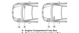
Ford Fusion - fuse box location
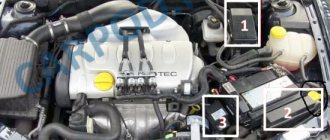
In the engine compartment
There are two mounting blocks in the engine compartment.
The power supply is located on the battery.
Next to the battery there is a square block with relay modules.
Relay block
| № | Business date, meeting |
| R1 | A/C shuts off when throttle is wide open |
| R2 | High speed engine cooling fan mode |
| R3 | Additional heater (RTS heater) |
| R4 |
Diagram of power block elements
| № | Decoding | Current, A |
| Does | Additional heater (RTS heater) | 80 |
| FB | Transmission of infection | 60 |
| F.C. |
| 60 |
| FD | Cooling fan and air conditioner | 40 |
| F.E. | Luminaires and General Electronic Module (GEM) | 60 |
| FF | Turn on | 60 |
| FG | Engine and lighting | 60 |
| FH | Heated windshield, ABS, ESP, windshield | 60 |
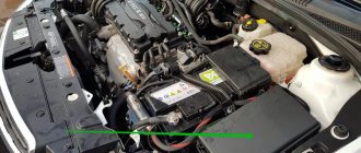
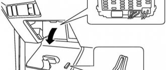
Mounting block
it is attached to the side of the battery on its positive cable and consists of high power fuses. To access it, you need to lift the battery itself.
Scheme
Designation
| Does | Additional heater 80A (RTS heater) |
| FB | Gearbox 60A |
| F.C. | 60A Auxiliary heater (RTS heater) / glow plugs (diesel engine) |
| FD | 40A Cooling Fan and Air Conditioner |
| F.E. | 60A Luminaires and General Electronic Module (GEM) |
| FF | Ignition 60A |
| FG | 60A Motor and lighting |
| FH | Heated windshield 60A, ABS, ESP, windshield |
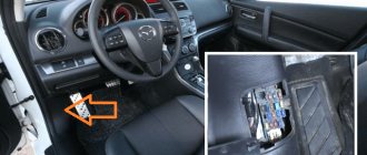
Ford Fusion Interior fuse box
| LHD | Right hand drive |
| № | A | Business date, meeting |
| F1 | — | Not used |
| F2 | — | Trailer connector |
| F3 | 7,5 | Lighting |
| — | Trailer connector | |
| F4 | 10 | Heating (air conditioning) and ventilation system |
| F5 | winds | ABS, ESP |
| F6 | thirty | ABS, ESP |
| F7 | 7,5 | Automatic transmission |
| 15 | Automatic transmission | |
| F8 | 7,5 | Power mirrors |
| F9 | 10 | Left low beam |
| F10 | 10 | Right low beam |
| F11 | 15 | Daytime Running Lights |
| F12 | 15 | The engine control unit |
| F13 | winds | Engine control unit, catalyst |
| F14 | thirty | Starter |
| F15 | winds | Gasoline pump |
| F16 | 3 | Engine control unit (memory) |
| F17 | 15 | Switch |
| F18 | 15 | Radio, diagnostic connector |
| F19 | 15 | Daytime Running Lights |
| F20 | 7,5 | Instrument panel, license plate light, battery, body electronics (GEM) |
| F21 | — | Not used |
| F22 | 7,5 | Left side light |
| F23 | 7,5 | Right side lights |
| F24 | winds | Central locking, anti-theft siren, body electronics module (GEM) |
| F25 | 15 | Signal lights, turn signals (Gear Electronics Module (GEM)) |
| F26 | winds | Heated rear window (body electronics module (GEM)) |
| F27 | 10 | Horn (Gear Electronics Module (GEM)) |
| 15 | Horn (Gear Electronics Module (GEM)) | |
| F28 | 3 | Battery, generator |
| F29 | 15 | Easier |
| F30 | 15 | Turn on |
| F31 | 10 | Switch |
| winds | Trailer connector | |
| F32 | 7,5 | Heated mirrors |
| F33 | 7,5 | Instrument panel, license plate light, battery, body electronics (GEM) |
| F34 | winds | Luke |
| F35 | 7,5 | Heated seats |
| F36 | thirty | Window lifters |
| F37 | 3 | ABS, ESP |
| F38 | 7,5 | Body electronics module (GEM (pin 15)) |
| F39 | 7,5 | Air bag |
| F40 | 7,5 | Transmission of infection |
| 10 | Low beam | |
| F41 | 7,5 | Automatic transmission |
| F42 | thirty | Heated windshield |
| F43 | thirty | Heated windshield |
| F44 | 3 | Radio, diagnostic connector (terminal 75) |
| F45 | 15 | Stop signal |
| F46 | winds | Front wiper |
| F47 | 10 | Rear wiper |
| 10 | Front wiper (high speed) | |
| F48 | 7,5 | Reversing lights |
| F49 | thirty | Heater motor |
| F50 | winds | Fog lights |
| F51 | 15 | Jack |
| F52 | 10 | Left high beam |
| F53 | 10 | Right high beam |
| F54 | 7,5 | Trailer connector |
| F55 | — | Not used |
| F56 | winds | Trailer connector |
| Relay | ||
| R1 | Power mirrors or Lighting fixtures | |
| R2 | Heated windshield or Low beam | |
| R3 | Turn on or Daytime running lights | |
| R4 | Low beam or Enable | |
| R5 | Dazzling or Starter | |
| R6 | Fuel pump or Fold mirrors | |
| R7 | Starter or Heated windshield | |
| R8 | Fan or Daytime Running Lights or Starter | |
| R9 | Daytime running lights or Engine control unit | |
| R10 | Loading system or Fold mirrors | |
| R11 | Engine control unit or fuel pump | |
| R12 | Power mirrors or Battery saver function |
Relay box in the engine compartment
| № | Relay |
| R1 | Air conditioning |
| R2 | Fan |
| R3 | Additional heater (RTS heater) or Reversing lights |
| R4 | Additional heater (RTS heater) |
Ford Fusion Fuse Diagram
The following fuses and relay descriptions are based on a 2008 vehicle.
Consider the interior module installed under the glove box.
| Position | Description |
| 1 | Spare safety element. |
| 2 and 3 | Trailer fuses. |
| 4 | Electrical supply for the heating unit. |
| 5/6 | ABS system supply voltage. |
| 7 | Durashift automatic transmission module. |
| eight | Electric exterior mirrors |
| 9/10 | Left and right headlights in low beam mode. |
| eleven | DRL connection. |
| 12 | ECU control unit responsible for the fuel injection system. |
| 13 | ECM module on diesel versions. |
| 14 | Apply voltage to the starter relay. |
| 15 | The same goes for the fuel pump. |
| 16 | ECU power supply circuits. |
| 17 | Toggle switches for external lighting devices. |
| 18 | Main unit power supply. |
| 19 | DRL lighting |
| winds | Power supply for instrument panel, rear license plate illumination. |
| 21 years old | Spare cell. |
| 22/23 | Respectively for left and right dimensions. |
| 24 | Power supply for central locking and sound signal. |
| 25 | Emergency lane power supply. |
| 26 year | Rear window heating system. |
| 27 | Klaxon and interior lamps. |
| 28 year | Power supply to the generator excitation winding. |
| 29 | Front cigarette lighter |
| thirty | Checking the ignition system. |
| 31 year | Steering column switch for external lighting. |
| 32 | Heated rear view mirrors. |
| 33 | Switches on the dashboard. |
| 34 | Reserve position. |
| 35 year | Heated front seats. |
| 36 | The windows work. |
| 37 | ABS controller power supply. |
| 38 | General electronic unit. |
| 39 | Check the airbag. |
| 40 | Automatic transmission controller |
| 41 years old | Spare fuse. |
| 42/43 | Windshield heaters. |
| 44 year | The main unit is powered by a battery. |
| 45 | Stop lights. |
| 46 | Front wiper power supply. |
| 47 | It's the same with the glass in the rear of the car. |
| 48 | Reversing light. |
| 49 | Electric heater fan drive. |
| 50 | Fog lights. |
| 51 | Rear cigarette lighter. |
| 52/53 | Left and right headlights of the main optics in high beam mode. |
| Relay | |
| 1 | Headlight switches. |
| 2 | Heated windshield. |
| 3 | Auxiliary ignition system. |
| 4/5 | Switches for headlights in low/high beam mode. |
| 6 | Fuel supply, ignition system. |
| 7 | Starter field windings. |
| eight | Power plant cooling fan drive. |
| nine | The daylight option is only used in Scandinavian countries. |
| 10 | Power output on the rear panel. |
| eleven | The main ignition system, through the immobilizer, generator. |
| 12 | Backup relay. |
We should also consider the module installed under the hood of the car.
| Marking | Description |
| Does | Autonomous heating system. |
| FB | Transmission controllers |
| F.C. | Additional heater or diesel glow plugs. |
| FD | Radiator cooling fan and air conditioning clutch. |
| F.E. | A single electronic lighting module for the entire vehicle. |
| FF | Ignition system. |
| FG | Basic engine electronics and lighting elements. |
| FH | Windshield heaters, ABS and ESP systems. |
A relay module is installed nearby.
| Serial number | Description |
| 1 | Turn off the A/C position when opening the throttle. |
| 2 | Radiator fan, high speed. |
| 3/4 | Power supply for autonomous heating systems. |
Ignition relay
The line is fed from the FF switch located under the hood of the car.
Trunk release safety device
Element 24, installed in the cabin, is responsible for the hood lock and other locking devices.
central locking
The information is given above.
Fuel pump relay and fuse
It is installed in the passenger compartment in position 15. The switch is located under the frame or its role is performed by the ECU.
Cigarette lighter fuse: where is it located?
The machine is initially equipped with 2 sockets. Inserts 29 and 51 installed in the cabin are responsible for their nutrition.
Starter fuse and relay
They are installed in the cab in two positions: 14 and 28. Power relays, depending on the configuration, can be installed next to each other, in positions 2 and 3. The starter retractor is installed in the usual position and is characterized by greater reliability and simplicity of design.
Horn fuse
It is switched on through element 24. The horn is protected by insert 27.
Stop signal
Power is supplied by fuse 45 installed in the vehicle interior.
ABS fuse: where is it located?
The system is protected by two inserts. Sensors - fuse 5. Device controller - insert 6. Elements are located under the instrument panel.
Reverse
The light is connected to the vehicle's on-board network through element 48.
Wiper fuse
Fuses 46/47 are assigned to the front and rear wipers.
Low beam relay
The light module is made through relay 4 installed in the car interior. The light block is controlled by the FE element.
Instrument lighting fuse
The lighting is connected to the vehicle's on-board network via insert 11.
Radio tape recorder
The system has 2 fuses due to the wiring which takes the stress off the fuse and wires. Here the 18/44 elements are responsible for supplying voltage.
Turns relay
They cannot be found in mounting panels or under interior trim. The GEM, a specially prepared unit for this purpose, is responsible for the operation of the device.
Generator relay
Installed inside the generator. The device is installed on the operating shaft of the unit and is removed only after complete disassembly of the support.
Cooling fan relay
The high-flow fuel system is sealed through an FD relay located under the hood. The low-speed part is connected by element 2 in the cabin.
Dimension fuse
The fuel system is organized by inserts 22/23 on the left/right side of the car.
Glow plug relay - where is it located?
The system is implemented only on diesel engines. Here the power line passes through the FC switch.
Heater fuse
The internal heater control system is installed through element 49. The power cores are taken out from rails R3/4. All elements are installed in the passenger compartment under the instrument panel.
Windshield washer
The power supply circuits of the pump electric motor are connected to the on-board circuit by fuse 46, located in the vehicle interior.
Mirrors
The control unit is connected to the battery through insert 8. The heating circuits are output to the mains through element 32.
Window lifters
The buttons are powered from insert 36 installed under the glove box. The servo power cores receive power from the FH relay in the engine compartment.
Theory, where would we be without it?
First, a few words about when the fan should turn on and what is considered normal. The cooling system fan turns on automatically as soon as the coolant temperature reaches a certain point, usually in the range from 85° to 100°.
When the engine is cold and it needs to quickly warm up the engine coolant through a small circle of the cooling system, bypassing the radiator, the electric fan is also turned off. As soon as the engine has warmed up to operating temperature, the thermostat is activated, which opens a large circle, that is, a circle with the participation of the radiator. This allows air flows to cool the antifreeze, preventing it from warming up above the permitted mark. But what to do if the air flow is not enough or the car has slowed down significantly or stopped altogether? The radiator cooling fan is specifically designed for these cases. It comes into operation when neither the large circle nor the air flow passing through the radiator honeycombs helps. The fan turns on automatically and forcibly cools the radiator, removing excess heat from it, thereby reducing the temperature of the coolant. If for some reason the fan suddenly does not work on a warm engine under load in the heat, this may mean that the coolant temperature will rise until cooling resumes. If the fan does not turn on, the engine temperature reaches a critical point, after which the engine boils, or rather the coolant boils, cooling is not carried out and the power unit works, which is called “peddling”. Even short-term overheating can have a detrimental effect on the condition of the motor and may result in an unpleasant breakdown in the future. Prolonged overheating usually ends with it boiling away and the motor simply “jamming”, after which it becomes completely incapacitated.
Checking and replacing fuses
Fuses and switches protect the vehicle's electrical system from overload. If the vehicle's electrical parts have failed, the system may have been overloaded and a fuse or circuit breaker has tripped. Before replacing or repairing any electrical parts, check the associated fuses or circuit breakers.
To check the fuse, look at the silver stripe inside the fuse. If the tape breaks or melts, replace the fuse.
Notification
- Before replacing fuses, ensure that the key has been removed from the panel and all services have been disabled and/or disabled.
- Always disconnect the battery before repairing high current fuses.
- Always replace the fuse with a fuse of the specified amperage. Using a higher rated fuse may seriously damage the cable and cause a fire.
- Never replace a broken fuse with anything other than a new one. Always use good fuses of the same color.
- If the fuse blows again, contact a qualified service center.
Recommendations for replacing pp
First of all, the driver must understand that the new fuse must match the type of its predecessor. Particular attention should be paid to the operating current. It happens that printed circuit boards look exactly the same, but have radically different transmission powers. In order not to miss this moment, pay attention to the markings. Usually it is printed on a plastic box.
Advice! If the new fuse also blows soon, then you should not immediately rush to replace it with a new one. We recommend that you contact SC and resolve the issue.
Why doesn't the fan work? Let's find out!
- Wiring and contact. Any of these reasons, despite their harmlessness, can be the reason why the fan simply does not turn on at the right time. It also often happens when the reason lies in the malfunction of the electric fan motor itself, which for one reason or another cannot start working. In cases with the electrical network, I would recommend finding an experienced electrician who will empirically determine the fault and answer the question of why the cooling fan does not turn on.
- Fuse. A blown fuse can also be attributed to common causes that occur quite often. An open circuit due to a blown fuse will prevent the electric fan from turning on, resulting in an increase in engine temperature. You can check the fuse very simply, just remove the fuse that is responsible for the operation of the fan, and replace it with a new fuse or simply insert a piece of wire in such a way as to close the circuit. If during the test the electric fan starts to work, then the reason is in the fuse.
- Air lock or low coolant level. Check the coolant level and the cooling system hoses. At operating temperature, the hoses leading to the radiator should be hot and the coolant level should be correct in both the expansion tank and the radiator. Be careful, checking the antifreeze level is only done on a cold engine. Also, if the fan does not work, you should pay attention to the circulation of antifreeze; after warming up, it should circulate in a large circle. If this is not the case, there may be an air lock in the system, how to remove it. A decrease in coolant level may indicate a leak in the cooling system. In the best case, it will be a question of replacing the cylinder head gasket, in the worst case, a crack in the block or a burnout.
- Temperature sensor. Thanks to this sensor, the electronic unit (ECU) decides whether to turn on the fan or not. Unstable operation or malfunction of this sensor will lead to the ECU receiving incorrect information about the coolant temperature, as a result of which the fan will not turn on.
- The last suspect is . If it is faulty, the circulation of antifreeze will be difficult, as a result, the operation of the fan will be compromised. For example, when the thermostat is stuck on the “small circle”, the fan does not turn off and runs constantly, because the engine is warmed up, the temperature rises and the fan tries to fix it all. The only problem is that due to the stuck thermostat, the liquid in the radiator does not circulate and cooling does not occur. In some cases, the opposite happens: the temperature sensor does not work, because the jammed one does not allow liquid to pass through a large circle, and as a result, the electric fan does not turn on.
That’s all I have, write in the comments about what reasons you know for a non-working fan, share your experience and perhaps your story will help someone solve their issue. Thank you for your attention and see you again on . Bye!
What batteries are supplied with Fiesta and Fusion at the factory?
The European design bureau of the American automobile brand, based on the fact that the engine sizes of both cars are small, decided to equip all configurations on all generations of both models with the same size battery.
The batteries are used in the most common European size battery on the market – 242x175x175 mm. The power of models in this group ranges from 55 to 63 A / h, the starting current is from 490 to 640 A.
The design of the engine compartment assumes the reverse arrangement of the electrodes on the power devices. Fastening is carried out by the lower pressure plate, so only models with a plastic tongue at the bottom of the device are suitable.
European version
Regardless of which of these covers you have, you need to know how to remove the bumper without anything breaking or damaging the bumper itself. How to remove the front bumper on a Ford Fusion with your own hands - step-by-step instructions 1.
Removing the Fusion front bumper does not require a lift or inspection hole, you just need to have a clear area to park the car and do the job. To keep things cool, spread some cardboard or foam underneath the "bottom point" or "edge" of an old, thick jacket.
Pull the handbrake or shift. Raise the hood, remove the “-” terminal of the battery. Next, you need to disassemble the fender liners; for this it is better to remove the wheel, but if there is no special desire, then it is not possible to remove it.
Unscrew the wing trim screws with an asterisk of suitable diameter.
Batteries suitable for installation on Ford Fiesta and Fusion
Here are a few battery models to consider for the vehicles in question:
- The most affordable are two models from German manufacturers - Varta Blues D59 and Bosch S4 004. It should be understood that Varta-Bosch has long been a single manufacturer, so the question of choice in this case is purely a preference for the name on adhesive devices. In addition, both models are produced in the same plant in Romania and have the same characteristics: power 60 A/h, current 540 A.
- The Korean model Inci - Aku SUPR A 60 RS (in one case low) has similar characteristics - power 60 a / h, current 540 A. The fact that Inci is a supplier of “stock” devices for many global brands indicates high reliability products of this brand.
- The group's domestic products are represented by the high-performance Maybe 60R model (in a small case): power 60 A/h, current 600 A.
- An interesting solution is offered by the Turkish brand MUTLU Mega Calcium 60R: battery capacity is 60 A/h with a cold start current of 540 A. The addition of calcium to the lead plates of the battery by the manufacturer significantly increases its service life.
- The best device in terms of performance is the product of the Korean company BOST - model Premium 63R (56377) with a power of 63 a / h and a current of 640 A.
All models listed have reverse polarity and are designed to be secured using a bottom clamp or bracket.
How to check the fan switch sensor
The need to check the sensor arises after the engine overheats or there is a suspicion of poor performance of the cooling system. First of all, it is necessary to check not the sensor, but the wires and relays that turn on the fan. To do this, remove the wires suitable for the sensor and short-circuit them; if there are not two, but three wires, then you need to short-circuit the middle one and each of the outer ones one by one. The fan should turn on at low and high speed, depending on which contacts are closed. If the fan turns on, it means that the wires and relays are working properly and you can start checking the sensor; if not, you need to find and eliminate the malfunction (broken wires, poor contact, blown fuse, burnt out relays or fan motor).
After making sure that the relay, motor and wires are working properly, proceed to checking the sensor. To do this, you will need a basin for coolant, a 30 key, a thermometer up to 100 degrees, a pan of water, a stove and a multimeter. Remove the terminal from the battery and place a basin under the car so that the coolant from the radiator does not pour onto the ground, but into it. Wait until the radiator cools down to 45 - 50 degrees, then unscrew the drain plug (it is located at the bottom of the radiator on the left or right side). After the liquid has drained, screw the plug into place. Remove the wires from the sensor (if there are 3 of them, then mark each one so that when installing a new sensor you do not mix them up), then unscrew the sensor with a 30 mm wrench.
Pour water into a saucepan so that it covers the working part of the sensor (up to the nut) and place it on the stove. Monitor the water temperature with a thermometer.
Use a multimeter to check the sensor contacts are triggered. For a three-pin one, it is advisable to use two multimeters. Turn the multimeter into resistance measurement mode with a sound signal and connect it to the sensor terminals. When the bimetallic strip closes the contacts, the multimeter will start beeping. Turn off the stove and wait until the multimeters turn off. Compare the thermometer readings at the moment the sensor contacts activate and turn off. If the deviation from the values written on the sensor body is more than 5%, it is advisable to replace it. If the deviation is more than 10%, or the sensor does not work at all, it must be replaced. Installation proceeds in the following order - screwing in the sensor, filling in coolant, connecting the battery.
Removing and installing the battery
You will need: key “10”, socket “13”, extension cord.
1. Turn off the ignition (if it was on) and open the hood.
2. Loosen the locking bolt nut of the ground cable lug...
3. and remove the tip of the wire from the negative terminal of the battery.
4. Remove the battery protective cover and the end of the terminal cable...
5 . loosen the nut...
6. and remove the cable terminal from the positive terminal of the battery.
7. Unscrew the two nuts securing the pressure plate...
8 . and remove the strip.
9. Remove the battery.
10. To remove the battery compartment, tighten the lock...
11... and move the fuse box to the side.
12. Remove the three bolts that secure the battery tray...
13 . two screws securing the engine management system controller...
14....slide the controller off the shelf and move the controller to the side.
15. Remove the battery compartment.
16. Install all previously removed parts in reverse order. Before connecting cables, clean the battery terminals and the inside of the lugs with fine-grit sandpaper. Connect the wires in the reverse order of removal, observing polarity. After connecting the cables to the battery terminals, apply a thin layer of Litol-24 or similar lubricant to the metal cable ends and exposed terminal surfaces (conductive lubricants containing copper are preferred).
Replacing the battery for Fiesta and Fusion
Since both cars are designed for a “lower” battery mount, the car enthusiast will need two keys from a standard car set: a flat key for 10 and a socket for 13.
The first step after opening the casing will be to loosen the clamp on the battery electrode, indicated by a minus sign, with a 10 wrench. The clamp is removed from the electrode.
Then a similar operation is performed on the positive terminal.
After the wires have been disconnected and moved to the side, use a socket wrench (preferably with an extension) to unscrew the bolt at the base of the battery that holds the pressure plate. The plate has been removed.
The old battery is removed and a new one is installed in its place.
After installing the new battery, the retaining clip is screwed back on. Then the positive clamp is connected and tightened tightly, and the “ground” is fixed last.”
Why do you remove the battery for the winter?
The guys here are simple: they take them off so they don’t “kill” the battery! If the machine is not working, but the terminals are crossed over the battery, the discharge microcurrents are still present, obviously, for some the losses are much greater, for others much less, but still there (by the way, let's read how to check this here). Also, do not forget about self-discharge currents; even the most ideal battery can discharge on its own during a long period of inactivity. Yes, to be honest, batteries are not always clean on top, meaning they can contain dirt, moisture (e.g. precipitation, evaporation, etc.), antifreeze and much more. All this can drain the battery, albeit slowly but surely.
Post-installation setup
If CD 6000 can still be reinstalled on a Ford Fusion, the date and time settings will be lost. They should be updated as the displayed data is also transmitted to the on-board computer. Typically, after rebooting, the head unit will display 12 pm, the date corresponding to the release date of the Ford Fusion. If you uninstall and install it, it will appear again this time. Unlocking also includes the output of this data.
Setting the date and time
The main unit has a special CLOCK button in the upper right panel. By clicking on it, you can easily adjust the date and time.
By pressing the "right" and "left" buttons, you can switch the selection: from time to date, from day to year or month. When you select one of the areas, you can change it using the slider. You have to scroll until you get the number you want, then remove your finger from the setting buttons and press Menu or Clock again.
How does it work and where is the fan switch sensor located?
The sensor is based on a bimetallic plate, which changes its shape with increasing temperature. When the coolant temperature exceeds the value indicated on the sensor body, bending of the bimetallic plate causes the sensor contacts to close. The electric current that passes through the sensor contacts turns on the power relay that controls the fan motor.
The sensor is located on the side of the radiator. On some models it is located at the top, on others in the middle. It is not difficult to recognize him. It looks like a large brass nut, to which two (less often three) electrical wires fit. When planning to change the fan switch sensor, consider the following. The lower the sensor response temperature, the lower it is set relative to the coolant level. The switching temperature of the sensors, which are installed at the bottom of the radiator, does not exceed 85 degrees. The temperature of the sensors is set in the middle of the radiator to 90 - 95 degrees.
Battery compatibility for Ford Fusion
If we take the type of battery and its size as the main criteria, then the domestic market offers a wide selection of batteries from different manufacturers. Despite the large assortment, there are not many batteries that are ideally compatible with the on-board network and transmission of a Ford Fusion.
Battery Ford 550 075 051
This battery is produced in Russia on modern equipment using advanced technologies. The battery is characterized by stable electrochemical characteristics, increased resistance to cyclic loads and a rapid increase in capacity during discharge. The battery life is at least 4 years, and the official manufacturer's warranty is 24 months. This is the most expensive battery on the list, but don't forget that this is an original Ford Fusion battery that is 100% compatible with the vehicle's electrical system.
Battery Varta Silver Dynamic C6 552 401 052
The battery of this model is characterized by increased starting currents by 15% (compared to the basic line of Varta batteries), which allows it to be installed on cars with a large number of additional electrical equipment. In terms of characteristics, the battery occupies one of the leading positions in its price segment. The manufacturer's official warranty is 24 months, which corresponds to the average service life of the battery itself.
Battery Berga PB-No.1
Among the main advantages of the Berga PB-No. 1 battery, it is worth noting high reliability, good vibration resistance and long-term preservation of the original electrochemical parameters. The grids are doped with calcium of the highest purity, so they are practically not subject to corrosion, which significantly increases the battery life. On average, batteries last at least 6 years, and the manufacturer provides an official quality guarantee of 48 months.
Battery Moll M3 Plus
The Moll M3 Plus battery has optimal technical characteristics and high capacity, which allows it to be installed in the Ford Fusion in the maximum configuration. The German manufacturer pays special attention to safe operation, so it has equipped the battery with a special cover with a built-in gas filter and flame arrester. The average battery life is at least 5 years, and the official warranty is 48 months.
How to choose a new sensor
To select the right sensor, you need to know the optimal coolant temperature at which it should turn on and off. For a VAZ 2110 car this is 92 and 87 degrees. The optimal sensor response temperature for another car is indicated in the repair and operating instructions for the car. Buy a sensor only in large stores and be sure to take a receipt. Before installing the sensor on the vehicle, check it as described above. If the difference between the temperature indicated on the sensor body and the temperature at which it actually operates exceeds 5%, replace it. Operating the motor at a temperature different from the optimal one greatly reduces its service life.
Source
Dismantling process
To begin with, you should understand that removing the bumper can be quite easy and simple and does not require much effort. In addition, there is no need to look for special equipment, for example, to work with the engine. Also, to disassemble the bumper, no hole or lifting is required, you only need a flat surface.
It should be understood that in order to remove the front bumper, it will be necessary to remove the accompanying parts, then a jack, a set of tools, which must contain Torx stars and other attachments, will come in handy.
Let's get to work:
- We remove the terminal from the battery so as not to accidentally short-circuit something and create even more problems.
- Remove the front wheels.
- To make the process easier, it is necessary to remove the mudguards and fenders.
Why are environmental classes necessary?
In just one year, just one ordinary car absorbs over 4,000 kg of oxygen contained in the atmosphere. And as a result of processing this oxygen, the engine emits about 800 kg of carbon monoxide, 200 kg of carbon, and 40 g of nitric oxide.
Since the number of cars increases every year, the state of the environment throughout the world in general and in each specific large city is quite deplorable. Environmental communities have been talking about this for a long time, but banning cars is hardly possible in principle.
For this reason, today cars are divided into environmental classes and are required to meet the standards of automakers. These classes mean a certain gradation of cars into categories, taking into account toxic substances that contain exhaust gases and evaporating fuel, for a specific make and model. Carbon monoxide, nitric oxide, heavy metals, and hydrocarbons pose a danger to humans and nature.
An example of car exhaust gases that violate Russian eco-standards
Bottom line
Fusion fuses are a reliable solution designed to protect electronic devices and components. The mounting blocks are easy to use and require no maintenance.
- https://FokSevmash.ru/hodovaya-chast-i-transmissiya/predohraniteli-ford-fyuzhn.html
- https://carpod.ru/predohraniteli-i-rele-ford-fiesta-fusion-2001-2008_3032.htm
- https://vsepredohraniteli.ru/ford/fusion.html
- https://knigaproavto.ru/shemy/ford/fusion/1597-shema-predohraniteley-i-rele-ford-fusion-2002-2012.html
- https://avtoehlektrika.ru/oborudovanie/gde-nahodyatsya-predohraniteli-ford-fyuzhn.html
- https://rus-avtomir.ru/predohraniteli/rele-fusion
- https://AvtoStandart-m24.ru/avtomobili-drugoe/blok-predohranitelej-ford-fyuzhn.html
- https://4838.ru/predohraniteli-i-bloki-rele-dlya-ford-fusion-eu-2002-2012-so-shemami-i-opisaniem/
- https://lando-spb.ru/remont-i-zamena/kak-snyat-akkumulyator-ford-fyuzhn.html
- https://aklaypart.ru/remont/kak-snyat-akkumulyator-ford-fyuzhn.html
- https://AvtoChehol.su/raznoe/kak-snyat-akkumulyator-ford-fyuzhn.html
- https://adaptsport.ru/remont/kak-snyat-akkumulyator-ford-fyuzhn.html
- https://stoatc.ru/remont/kak-snyat-akkumulyator-ford-fyuzhn.html
- https://myducato.ru/ford/kak-snyat-akkumulyator-ford-fyuzhn.html