The 5th Volkswagen Golf was produced in 2003, 2004, 2005, 2006, 2007, 2008 and 2009, mainly in a hatchback body, with both gasoline and diesel engines. In our material you will find a description of the fuse and relay blocks of the Volkswagen Golf 5 with diagrams and photographs. We will show you the location of all electronic control units. Separately, we note the fuse responsible for the cigarette lighter. This material will also be useful to the owner of a Volkswagen Jetta 5, since these models have a similar electrical circuit.
Isn't it the right generation? Study the description for either accordingly.
General arrangement of control units
Scheme
Designation
| 1 | Electronic air conditioning control unit |
| 2 | Air conditioner/heater fan motor control unit |
| 3 | Side impact sensor, driver's side |
| 4 | Side impact sensor, rear left |
| 5 | Side impact sensor, passenger side |
| 6 | Side impact sensor, rear right |
| 7 | Vehicle tilt sensor (anti-theft system) |
| 8 | Accumulator battery |
| 9 | Diagnostic connector (DLC) |
| 10 | Data bus connector |
| 11 | Driver's door electrical control unit - in the door |
| 12 | Left rear door electrical control unit |
| 13 | Passenger door electrical control unit - in the door |
| 14 | Right rear door electrical control unit |
| 15 | Cooling Fan Motor Control Module - On Cooling Fan Motor |
| 16 | Fuse/Relay Box, Engine Compartment 1 |
| 17 | Fuse/Relay Box, Engine Compartment 2 |
| 18 | Engine Compartment Fuse/Relay Box 3 - Under Engine Compartment Fuse/Relay Box 1 |
| 19 | Fuse/Relay Box, Instrument Panel 1 |
| 20 | Fuse/Relay Box, Instrument Panel 2 |
| 21 | Fuse/Relay Box, Instrument Panel 3 |
| 22 | Headlight range control unit (models with xenon headlights |
| 23 | Heater fan motor resistor |
| 24 | Beep 1 |
| 25 | Beep 2 |
| 28 | Instrument cluster control unit |
| 29 | Multi-function control unit 1 - in the instrument panel fuse/relay box 3-functions: Cigarette lighter, cruise control, fog lights, hazard warning lights, headlights, rear defroster, horn, interior lights, rear window wiper/washer, rear lights travel, front dimensions, brake lights, windshield washer, windshield wiper |
| 30 | Multi-function control unit 2 - functions: Anti-theft system, trunk/rear door lock, trunk/rear door opening drive, central locking, power door mirrors, power windows, fuel filler flap drive, sunroof |
| 31 | NOx sensor control unit - under the body |
| 32 | Parking system control unit - right luggage compartment |
| 33 | Power steering control unit - above the steering rack |
| 34 | Electronic control unit SRS |
| 35 | Steering column electrical control unit |
| 36 | Telephone control unit - under seat, if installed |
| 37 | Trailer electrical control unit - left luggage compartment |
| 38 | Electronic transmission control unit - behind the wheel arch |
| 39 | Windshield wiper control unit - on the intake system resonator |
Removal and replacement process
To replace fuses in a Volkswagen Jetta V, you will need a slotted screwdriver.
In the engine compartment
The procedure is as follows:
- Immobilize the car, remove the terminal from the negative terminal of the battery.
- Open the mounting block.
- Take tweezers from the cover and pull out the blown fuse. Its condition can be checked by examining it in front of a light source. If the fuse is blown, a broken jumper will be visible. If you need to replace the relay, pull it towards you, swinging it from side to side.
- Insert new spare part.
- Check the operation of the protected circuit. If necessary, find and eliminate the short circuit.
- Install the removed parts in reverse order.
In the cabin
The procedure is as follows:
- Open the driver's door.
- Remove the cover of the interior mounting block on the left end of the dashboard by lifting it with a screwdriver.
- Pull out the supposedly blown fuse/broken relay and replace it with a new one.
- Repeat steps 4-6 from the previous method.
This completes the replacement.
To summarize, we can say that the fuses in the Volkswagen Jetta V are located in 2 places: in the cabin and under the hood. No special tools are required to replace fuse links.
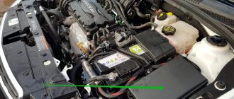
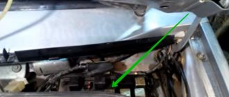
Fuse and relay box under the hood
It is located next to the battery and is covered with a protective cover. Consists of two blocks. 1 - Department of high power fuses in the form of fuse links. 2 - fuse and relay department.
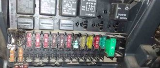
Fuse and relay box
Option 1
Photo - example
Scheme
Purpose
| 1 | Engine control relay |
| 2 | Exhaust air pump relay |
| F1 | (30A) Windshield wiper |
| F2 | (5A) Steering column electrical control unit / (30A) Mechatronic unit for DSG gearbox |
| F3 | (5A) On-board power supply control unit |
| F4 | (30A) ABS electronic control unit |
| F5 | (15A) Electronic gearbox control unit |
| F6 | (5A) Instrument cluster |
| F7 | (40A) Power relay |
| F8 | (15A) Audio system / Head unit |
| F9 | (5A) Telephone control unit |
| F10 | (5A/10A) Electronic engine control unit |
| F11 | (20A) Additional heater control unit |
| F12 | (5A) CAN data bus, gateway control unit |
| F13 | (15A/30A) Electronic engine control unit |
| F14 | (20A) Engine management system, Ignition coil |
| F15 | (5A/10A) Engine management system, Lambda probe |
| F16 | (30A) ABS electronic control unit, Right headlight |
| F17 | (15A) Horn |
| F18 | (30A) Audio system |
| F19 | (30A) Windshield wiper/washer |
| F20 | (10A) Coolant pump |
| F21 | (10A/15A) Engine management system, Lambda probe, Electromagnetic clutch of supercharger drive |
| F22 | (5A) Clutch pedal limit switch (position sensor) |
| F23 | (5A/10A/15A) Engine management system, Fuel pressure regulator, Secondary air pump relay |
| F24 | (10A) Engine management system, EGR valve, Solenoid valve |
| F25 | (40A) ABS control unit |
| F26 | (30A) Left headlight |
| F27 | (50A) Glow plug control unit |
| F28 | (40A) Main ignition circuits |
| F29 | (50A) Seat position adjustment thermal fuse 1 |
| F30 | (40A) Starting system (50A) X contact relief relay |
Option 2
Photo
Scheme
Description
| 1 | Relay 2 main ignition circuits |
| 2 | Starter relay |
| 3 | Fuel pump relay - 1.4 (BCA) / 1.6 (BGU) |
| 4 | Relay 1 main ignition circuits |
| F1 | (30A) ABS |
| F2 | (30A) ABS |
| F3 | (20A) Multifunction control unit 2 |
| F4 | (5A) Multifunction control unit 1 |
| F5 | (20A) Horn |
| F6 | (5A/20A) Motor control |
| F7 | (5A) Brake light switch (brake pedal position sensor), clutch pedal position sensor |
| F8 | (10A) Cooling fan motor control unit, engine control |
| F9 | (10A) Motor control |
| F10 | (10A) Motor control |
| F11 | (25A) Engine control - petrol |
| F12 | (15A) Motor control |
| F13 | (20A) Automatic transmission |
| F14 | — |
| F15 | (40A) Starter |
| F16 | (15A) Steering column electrical control unit |
| F17 | (10A) Instrument cluster |
| F18 | — |
| F19 | (15A) Audio system, navigation system |
| F20 | (10A) Telephone |
| F21 | — |
| F22 | — |
| F23 | (10A) Cruise Control |
| F24 | (10A) Data bus connector |
| F25 | — |
| F26 | (5A) Engine Control - Diesel |
| F27 | (10A) Crankcase ventilation heater |
| F28 | (20A) Automatic transmission |
| F29 | (20A) Motor control |
| F30 | (20A) Heater/air conditioner |
| F31 | (25A) Windshield wiper |
| F32 | (10A) Motor control |
| F33 | (15A) Fuel priming pump |
| F34 | — |
| F35 | — |
| F36 | — |
| F37 | — |
| F38 | (10A) Headlight range control |
| F39 | (5A) Engine oil temperature sensor, instrument cluster |
| F40 | (20A) Instrument panel fuse/relay block 1 (F1-F11/ F29-F31) |
| F41 | — |
| F42 | (5A) Engine Control - Gasoline |
| F43 | — |
| F44 | — |
| F45 | — |
| F46 | — |
| F47 | (40A) Multifunction control unit 1 |
| F48 | (40A) Multifunction control unit 1 |
| F49 | (50A) Multifunction control unit 1 |
| F50 | (40A) Audio system |
| F51 | (50A) Glow plug control unit |
| F52 | (50A) Multifunction control unit 1 |
| F53 | (50A) Instrument panel fuse/relay block 1 (P32-B37), instrument panel fuse/relay block 2(F4) |
| F54 | — |
Fuse block
Option 1
Decoding
- 150A/200A – Generator
- 80A - Power steering control unit
- 50A - Radiator fan and its control unit
- 40A - Low heating power relay or Additional equipment
- 100A - Fuses in the cabin
- 80A - Fuses in the cabin, 100A - additional equipment
- 30/40/50A - Trailer connection and additional equipment
Option 2
Designation
- 150A/200A – Generator
- 80A - Power steering unit
- 50A - Radiator fan and its control unit
- 40A - Fuses in the cabin
- 100A - Fuses in the cabin, 80A - additional equipment
- 80A - Fuses in the cabin, 100A - additional equipment
- 50A - Reserve
In some models, it is possible to locate additional relays outside the unit: glow plug control relay and air supply pump relay.
Volkswagen Jetta 5 fuses
To prevent damage to electrical devices or vehicle circuits, the fifth generation Volkswagen Jetta, produced from 2005 to 2010, uses fuses and fuses. They are located in modular blocks along with the relays.
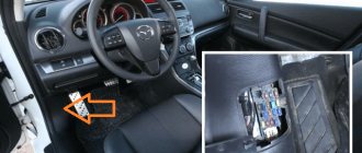
Where are the fuse boxes located?
In the VolksWagen Jetta 5, the manufacturer assembled all the fuses in two blocks:
- Engine block - located in the engine compartment on the driver's side, next to the brake fluid expansion tank.
- Interior module - located on the side of the instrument panel on the driver's side.
Underhood fuse module
To access the fuse and relay motor module, you must move the cover fastening elements towards the vehicle and remove it. After checking and replacing the board, you need to replace the cover, return the clamps to their original position and make sure that the unit is tightened well.
Location of fuses in the motor module.
Protected circuit or electrical equipment Rating, A Color coding No.
| Connector not used | 1 | ||
| Steering column switches | 5 | Light yellow | 2 |
| OBDII connector for diagnostics | 5 | Light yellow | 3 |
| ABS system unit, electronic components | thirty | Light green | 4 |
| Automatic transmission controller | 15 | Blue | 5 |
| Tools on the panel | 5 | Light yellow | 6 |
| Connector not used | 7 | ||
| Radio in the center console | 15 | Blue | eight |
| GSM phone | 5 | Light yellow | nine |
| Engine controller, relay | 5 | Light yellow | 10 |
| Internal Heater Fan Controller, Auxiliary Heater Controller | winds | Yellow | eleven |
| OBDII diagnostic bus controller | 5 | Light yellow | 12 |
| ECU, engine controller | 15 | Blue | 13 |
| Relay + 12V on-board network | winds | Yellow | 14 |
| Exhaust gas oxygen sensor, fuel pump, diesel internal combustion engine glow plugs | 15 | Blue | 15 |
| ABS system unit, electronic components | thirty | Light green | 16 |
| Horn | 15 | Blue | 17 |
| OEM audio amplifier | thirty | Light green | 18 |
| Wipers | thirty | Light green | 19 |
| Connector not used | winds | ||
| + 12V heated lambda probe | 15 | Blue | 21 years old |
| Brake pedal switch, clutch pedal switch | 5 | Light yellow | 22 |
| Intake manifold air recirculation pump, high pressure fuel pump, air flow sensor (DFID) | 10 | Red | 23 |
| EGR valve | 10 | Red | 24 |
| Headlight, right side | thirty | Light green | 25 |
| Headlight, left side | thirty | Light green | 26 year |
| Air recirculation pump in the intake manifold, engine warm-up mode | 40 | Orange | 27 |
| Engine starter relay | 40 | Orange | 28 year |
| + 12V at pin 30 | 40 | Orange | 29 |
| Contact X | 40 | Orange | thirty |
| Auxiliary cooling fan motor relay | R1 | ||
| Automatic transmission controller relay | R2 |
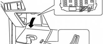
Cabin module of fusible elements
To access the fifth generation Volkswagen Jetta cabin module fuses, the driver's door must be open and locked. There is a fuse cover on the side of the instrument panel. To open it, you need to pry the outer edge with a screwdriver and pull it out.
PP cabin block pinout
Protected circuit or electrical equipment Rating, A Color coding No.
| Connector not used | 1 | ||
| Steering column switches | 5 | Light yellow | 2 |
| OBDII connector for diagnostics | 5 | Light yellow | 3 |
| ABS system unit, electronic components | thirty | Light green | 4 |
| Automatic transmission controller | 15 | Blue | 5 |
| Tools on the panel | 5 | Light yellow | 6 |
| Connector not used | 7 | ||
| Radio in the center console | 15 | Blue | eight |
| GSM phone | 5 | Light yellow | nine |
| Engine controller, relay | 5 | Light yellow | 10 |
| Internal Heater Fan Controller, Auxiliary Heater Controller | winds | Yellow | eleven |
| OBDII diagnostic bus controller | 5 | Light yellow | 12 |
| ECU, engine controller | 15 | Blue | 13 |
| Relay + 12V on-board network | winds | Yellow | 14 |
| Exhaust gas oxygen sensor, fuel pump, diesel internal combustion engine glow plugs | 15 | Blue | 15 |
| ABS system unit, electronic components | thirty | Light green | 16 |
| Horn | 15 | Blue | 17 |
| OEM audio amplifier | thirty | Light green | 18 |
| Wipers | thirty | Light green | 19 |
| Connector not used | winds | ||
| + 12V heated lambda probe | 15 | Blue | 21 years old |
| Brake pedal switch, clutch pedal switch | 5 | Light yellow | 22 |
| Intake manifold air recirculation pump, high pressure fuel pump, air flow sensor (DFID) | 10 | Red | 23 |
| EGR valve | 10 | Red | 24 |
| Headlight, right side | thirty | Light green | 25 |
| Headlight, left side | thirty | Light green | 26 year |
| Air recirculation pump in the intake manifold, engine warm-up mode | 40 | Orange | 27 |
| Engine starter relay | 40 | Orange | 28 year |
| + 12V at pin 30 | 40 | Orange | 29 |
| Contact X | 40 | Orange | thirty |
| Auxiliary cooling fan motor relay | R1 | ||
| Automatic transmission controller relay | R2 |
Blocks in the cabin
Fuse box
It is located at the end of the dashboard on the driver's side behind the protective cover.
Scheme with purpose
Detailed description
| F1 | (10A) Diagnostic connector DLC, Engine control unit, Relay for operation in auxiliary heater mode |
| F2 | (5A) АВS, ESP |
| F3 | (10A) Power steering, (5A) airbag control unit |
| F4 | (5A) Seat heater, heater/air conditioner, climate control unit, oil level and temperature sensor, reversing light |
| F5 | (5A) Brake light switch (brake pedal position sensor), clutch pedal position sensor, adaptive lighting and headlight range control unit, on the right headlight |
| F6 | (5A) Data bus connector, engine control, instrument cluster control unit, adaptive lighting and headlight range control unit, on the left headlight |
| F7 | (5A) Headlight range control unit, interior mirror |
| F8 | (5A) Interior rear view mirror, (10A) - Trailer control unit |
| F9 | (5A) Electronic control unit 4WD, navigation system |
| F10 | (5A) Telephone, seat occupancy detection unit |
| F11 | (5A) Trailer electrical control unit |
| F12 | (10A) Door electrical control unit (driver), door electrical control unit (passenger), central locking |
| F13 | (10A) Diagnostic connector, light switch, rain and light sensor |
| F14 | (5A) Brake light switch (brake pedal position sensor), automatic transmission control unit, ABS control unit |
| F15 | (7.5A) Multifunctional control unit (interior lighting) |
| F16 | (10A) Heater/air conditioner, antenna selection control unit |
| F17 | (5A) Audio system, rain sensor (windshield wiper), anti-theft alarm horn |
| F18 | (5A) Parking system control unit, selector lever position sensor |
| F19 | (5A) Emergency data recorder |
| F20 | (5A) Anti-lock brake system |
| F21 | (5A) Control unit for limiting maximum engine speed, in the footwell on the front left (special vehicles) |
| F22 | (40A) Supply fan |
| F23 | (30A) Power windows, door control unit |
| F24 | (25A) Cigarette lighter fuse front and rear, central control unit for comfort systems |
| F25 | (25A) Multifunctional control unit (rear window heating element, air conditioning control unit, heater and operating mode selection switch) |
| F26 | (20A) Charging connector (socket) (25A) Rear door control unit |
| F27 | (15A) Engine control (fuel pump) |
| F28 | (25A) Inverter with socket for special vehicles |
| F29 | (10A) Motor control |
| F30 | (5A) Airbag (10A) Injectors (20A) Automatic transmission control unit |
| F31 | (5A) Reversing lights (20A) Brake vacuum pump |
| F32 | (15A) Power windows |
| F33 | (25A) Hatch |
| F34 | (15A) Electric seats |
| F35 | (5A) Anti-theft system |
| F36 | (20A) Headlight washers |
| F37 | (30A) Seat heater |
| F38 | (20A) Anti-theft alarm horn relay, convenience systems central control unit |
| F39 | — |
| F40 | (40A) Heater/air conditioner |
| F41 | (15/20A) Rear window wiper/washer |
| F42 | (15/20A) Windshield washer, Cigarette lighter |
| F43 | (15A) Trailer electrical control unit |
| F44 | (20A) Trailer electrical control unit |
| F45 | (15A) Trailer electrical control unit |
| F46 | (5A) Air conditioning/heating system, heater and windshield washer nozzles |
| F47 | (5A) Heater/air conditioner |
| F48 | (7.5A) Power seats, power steering column adjustment, Charger for Mag-Lite flashlight and walkie-talkie |
| F49 | (7,5) Light switch |
Depending on the configuration and year of manufacture, fuses 24 or 42 are responsible for the cigarette lighter.
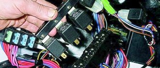
Relay block
The relay block is located under the instrument panel on the driver's side and consists of 2: main and additional.
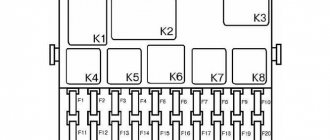
Basic
Scheme
Designation
| 1 | — |
| 2 | Heated mirror relay |
| 3 | — |
| 4 | Multifunction control unit relay |
| 5 | Rear window defroster relay |
| 6 | Horn relay |
| 7 | Windshield washer pump relay 1 |
| 8 | Windshield washer pump relay 2 |
| 9 | Auxiliary Ignition Relay |
Additional
Scheme
Purpose
| 1 | Headlight washer pump relay |
| 2 | Fuel lift pump relay - Diesel |
| 3 | Starter relay |
| 4 | Headlight washer pump relay |
| 5a | Start relay (fuel system) |
| 5b | Auxiliary heater relay |
| A | 30A Thermal fuse 1 driver's seat adjustment |
| IN | 30A Thermal fuse 2 driver's seat adjustment |
Checking the health of fuses
If the functionality of any vehicle device malfunctions, it is necessary, using Tables 1 and 2, to determine which fuses serve this element. Then you need to turn off the ignition.
In some cases (failure of the engine control unit, generator, side lights, cigarette lighter, etc.), it is better to remove the negative terminal of the battery. Then, using special dielectric pliers (you can use pliers), you need to disassemble the necessary fuses.
Testing fuses without removing them from the block may give an erroneous result.
Fuses in transparent housings can be checked visually. It should be remembered that this method of fault monitoring does not have a 100% guarantee, since sometimes it is not possible to see a microcrack in the conductive insert.
It is best to use the multimeter in the "diode", "resistance" or "continuity" test positions. The resistance value of a good fuse is approximately zero. The resistance of a blown fuse tends to infinity (the multimeter displays “1”).
Internal fuse block
The interior fuse module does not have connectors for relays, but consists only of PCBs. It is quite compact and easy to maintain.
| Protected electrical network or device | Nominal value, A | Color coding | Number on the diagram |
| Not used | 1 | ||
| Steering wheel lock | 5, 7,5 | Brown | 2 |
| Instruments on the panel | 10 | Red | 3 |
| GSM phone antenna | 2 10 | Red | 4 |
| Rear fog lamp, left side | 7.5 | Brown | 5 |
| Multifunction controller | 10 | Red | 6 |
| Brightness of instruments and buttons, fog lamp relay, rear number plate illumination | 5 | Brown | 7 |
| Headlight washer system | 7.5 | Brown | 8 |
| Airbag system | 5 | Brown | 9 |
| Steering column switches, right side | 10 | Red | 10 |
| Not used | 11 | ||
| Not used | 12 | ||
| Complex fuse: | 5 | Brown | 13 |
| headlight range control controller; | |||
| rearview mirror; | |||
| mirror heating button; | |||
| light sensor; | |||
| parking sensors; | |||
| mirror adjustment; | |||
| climate control; | |||
| heated washer; | |||
| TPMS button; | |||
| Start/Stop system | |||
| Diagnostic bus, steering column switch left side, fuel pump controller unit, towed trailer recognition system, inverter-stabilizer 12V - 220V | 10 | Red | 14 |
| Diagnostic connector, headlight range control, interior fan relay, instrument and button backlight adjustment, mass air flow sensor | 10 | Red | 15 |
| Relay for additional engine cooling pump | 10 | Red | 16 |
| Standard alarm | 10 | Red | 17 |
| Headlight, left | 15 | Blue | 18 |
| Headlight, right | 15 | Blue | 19 |
| Additional heater antenna, starter interlock, automatic transmission selector, climate control, automatic transmission controller | 10 | Red | 20 |
| On-board power supply controller, two-tone horn | 15 20 | Blue yellow | 21 |
| OEM alarm bell, ignition breaker, OEM relay, cabin volume sensor, converter controller | 7,5 20 | Brown, yellow | 22 |
| Compass, rain, light sensor, interior lighting switch, on-board network controller | 10 | Red | 23 |
| Headlight range control controller with adaptive lighting | 10 | Red | 24 |
| checkpoint | 15 | Blue | 25 |
| Brake booster pump | 15 | Blue | 26 |
| Airbag system | 1 | 27 | |
| Additional coolant heating | 40 | Orange | 28 |
| Multifunction controller | 1 | 29 | |
| Cigarette lighter | 20 | Yellow | 30 |
| Backlight button, front | 30 | Green | 31 |
| Backlight switch, rear | 20 | Yellow | 32 |
| Interior fan speed adjustment, auxiliary heater adjustment, climate control controller | 40 | Orange | 33 |
| Left and right headlight bulbs, high beam | 15 | Blue | 34 |
| Steering column controller, horn | 10 | Red | 35 |
| Multifunction controller | 25 | 36 | |
| Daytime running lights, left side | 15 | Blue | 37 |
| Daytime running lights, right side | 15 | Blue | 38 |
| Low beam bulbs, left and right | 20 | Yellow | 39 |
| Trailer on-board electrical controller | 15 | Blue | 40 |
| Trailer on-board electrical controller | 15 | Blue | 41 |
| Trailer on-board electrical controller | 20 | Yellow | 42 |
| Rear right door electrical module | 30 | Green | 43 |
| Rear window heating, heating relay | 30 | Green | 44 |
| Front door electrical module | 30 | Green | 45 |
| Rear left door electrical module | 30 | Green | 46 |
| Gasoline pump, booster pump for diesel internal combustion engines | 15 | Blue | 47 |
| Multifunction controller | 20 | Yellow | 48 |
| Climate control | 40 | Orange | 49 |
| Heated driver and passenger seats | 30 | Green | 50 |
| Power sunroof | 20 | Yellow | 51 |
| Klaxon | 20 | Yellow | 52 |
| Heated rear passenger seats | 15 | Blue | 53 |
| Rear fog lights | 15 | Blue | 54 |
| Interior and trunk light switch | 20 | Yellow | 55 |
| Not used | 56 | ||
| GPS navigator, audio preparation | 15 20 | Blue yellow | 57 |
| Connecting additional devices | 30 | Green | 58 |
| Standard audio amplifier | 30 | Green | 59 |
| Coolant heating | 30 | Green | 60 |
List of relays
Relay for VW Passat B3 and B4:
| Number | Purpose |
| 1 | Air conditioner |
| 2 | Rear windshield wiper |
| 3 | Power unit control, increasing rotation speed x/x |
| 5 | Antifreeze level sensor |
| 6 | "Emergency" |
| 7 | Cleaning the optics |
| 8 | Intermittent activation of windshield washer and wiper |
| 9 | Passenger or driver unbelted sensor |
| 10 | PTF |
| 11 | Horn |
| 12 | Fuel pump, intake manifold heating |
| 13 | Timer for rear glass heating |
| 15 | ABS pump |
| 16 | ABS |
| 19 | Air conditioner |
| 21 | Window drive |
| 22 | ABS valve system |
There are no descriptions for the relays missing from the table, since they are backup.
Relay for VW Passat B3 and B4. Photo source: https://zapchasti.lviv.ua/product/8434510770/
In the B5 generation, the car has three blocks with relays: Z13, R, Z8. The first two are combined into a single one, the latter is installed only on maximum trim levels, where there are many functions.
Block Z13
| Number | Purpose |
| 1 | Additional fan for air conditioner |
| 2 | Clutch (clutch) |
| 3 | Elements for turning on the air conditioner |
| 4 | Air conditioner |
| 5 | Fuel pump in diesel versions |
| 6 | Lighting (external) |
| 7 | Front optics |
| 8 | "Candles" |
| 10 | PTF |
| 11 | Connection |
| 12 | Starter |
| 13 | Anti-theft lock |
Block R
| Number | Purpose |
| I | Horn |
| II | Relay in contact X |
| III | Window washer |
| IV | Fuel pump, spark plugs |
| A | Connector 1 in luggage compartment |
| B | Connector 2 in luggage compartment |
Block Z8
| Number | Purpose |
| 2 | ABS/EDS/ESC |
| 3 | ABS/EDS/ESC |
| 4 | Fan for 1st stage |
| 5 | Fan at maximum |
| 6 | Fan for 2nd stage |
| A | Fan |
| B | Fan |
| C | Hydraulic pump |
Block under the "tidy"
| Number | Purpose |
| 1 | "Stove" (optional) |
| 3 | Fan providing additional air supply |
| 5 | Fuel pump (diesel) |
| 6 | Optics washer |
| 7 | Voltage at terminal 50 |
On the Passat B7, the relay for the electronic systems of the power unit is located in a block next to the battery. There is also an additional section with a similar element for “candles”.
There are three relay blocks installed in the panel inside the machine. The first contains elements for the stove fan and crankcase ventilation heater. In the second relay there is an additional “battery”. The third block contains a relay for heated glass at the rear and a similar element for auxiliary ignition circuits.
Fuses Volkswagen Golf 6, 2008 - 2013
The main power supply circuits of the vehicle's electrical equipment are protected by fuses. Headlights, fan motors, fuel pump and other powerful consumers are connected via relays. Fuses and relays are installed in mounting blocks, which are located in the engine compartment and interior of the car. The information is relevant for Volkswagen Golf 6 models 2008, 2009, 2010, 2011, 2012, 2013.
In the cabin
1) To access the mounting fuse block located in the passenger compartment... 2) Pry up the edge of the mounting block cover 3) overcoming the resistance of the latches, remove the cover
Fuses in the mounting block located inside the car
| Number | Current, A | Protected circuit |
| 1 | 10 | Control unit for electric headlight corrector and instrument cluster illumination brightness, parking assistance system |
| 2 | 10 | Brake light switch, ambient light switch, ABS system, instrument cluster, electric power steering, fuel module |
| 3 | 5 | Restraint control unit |
| 4 | 5 | Emergency oil level drop sensor, heating system control unit, ventilation air conditioning control unit, ASR switch, reverse light switch, interior rear view mirror with automatic dimming, automatic parking system |
| 5 | Reserve | |
| 6 | ||
| 7 | ||
| 8 | ||
| 9 | ||
| 10 | ||
| 11 | ||
| 12 | 10 | Window control unit |
| 13 | 10 | Exterior light switch, diagnostic connector, rear view camera, rain and light sensors |
| 14 | 10 | Heating, air conditioning and ventilation control unit |
| 15 | 20 | Body equipment control unit |
| 16 | Reserve | |
| 17 | 5 | Alarm buzzer |
| 18 | Reserve | |
| 19 | ||
| 20 | ||
| 21 | ||
| 22 | 20 | Air blower |
| 23 | 30 | Front door power window control keys |
| 24 | 20 | Rear door power window control keys |
| 25 | 25 | Electrically heated tailgate window |
| 26 | 30 | Rear door power window control keys |
| 27 | 15 | Gasoline pump |
| 28 | Reserve | |
| 29 | ||
| 30 | 20 | Mechatronic unit for robotic gearbox |
| 31 | 20 | Brake vacuum pump |
| 32 | 30 | Socket for connecting additional equipment |
| 33 | 25 | Power sunroof |
| 34 | 15 | Front seat lumbar support adjustment switch |
| 35 | 10 | Electronic damping control system control unit |
| 36 | 20 | Headlight washer pump |
| 37 | 30 | Front seat heating control unit |
| 38 | Reserve | |
| 39 | ||
| 40 | ||
| 41 | 15 | Tailgate window wiper motor |
| 42 | 20 | Cigarette lighter |
| 43 | 15 | Trailer stability control unit |
| 44 | 20 | |
| 45 | 15 | |
| 46 | Reserve | |
| 47 | ||
| 48 | ||
| 49 |
Relay in the mounting block located in the passenger compartment
| Number | Switched circuit |
| R1 | Ignition switch positive terminal relay |
| R2 | Horn relay |
| R3 | Headlight washer relay |
| R4 | Ignition switch power circuit unloading relay |
| R5 | Tailgate window heated relay |
| R6 | Fuel module relay |
In the engine compartment
1) To access the fuses and the relay-mounting block located in the engine compartment, open the hood. 2) Slide the cover fastening latches forward...3) and remove the cover.
Fuses and relays in the mounting block located in the engine compartment
| Number | Current, A | Protected circuit |
| 1 | 30 | Front and right rear turn signal lamps, right brake lamp, front and right rear parking lamps, right reversing lamp, right low and high beam lamps, right fog lamp |
| 2 | 15 | Sound signal |
| 3 | 40 | Air pump |
| 4 | Reserve | |
| 5 | 50 | Main fuse |
| 6 | 50 | Ignition switch power circuit unloading relay |
| 7 | Reserve | |
| 8 | 30 | Windshield wiper motor |
| 9 | Right tail light lamp | |
| 10 | 15 | Oxygen concentration sensor |
| 11 | 5 | Brake light switch |
| 12 | 5 | Intake geometry variable valve |
| 13 | 10 | Air pump relay, power supply injector |
| 14 | 30 | Windshield wiper motor |
| 15 | 30 | Mechatronic unit for robotic gearbox |
| 16 | 5 | Interior equipment control unit |
| 17 | 20 | ABS control unit |
| 18 | 15 | Mechatronic unit for robotic gearbox |
| 19 | 5 | Instrument cluster |
| 20 | 40 | Ignition switch positive terminal relay |
| 21 | 15 | Audio head unit |
| 22 | 40 | ABS control unit, electric module pump |
| 23 | 30 | Front and left rear turn signal lamps, left brake lamp, front and left rear parking lamps, left reversing lamp, left low and high beam lamps, left fog lamp |
| 24 | Reserve | |
| 25 | 5 | Diagnostic connector |
| 26 | 15 | ECU |
| 27 | 20 | Fuel pump, ignition coil |
| 28 | 10 | Control oxygen concentration sensor |
| 29 | 5 | Telephone communication device (optional) |
| 30 | 10 | ECU |
| R1 | Air pump relay | |
| R2 | ECU power relay |