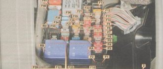
What are the VAZ 2110 fuse box relays responsible for?
K1 – relay for monitoring the health of light bulbs; K2 – front wiper relay; K3 – repeater and alarm relay; K4 – low beam relay; K5 – high beam relay; K6 – additional relay; K7 – relay for turning on the heated rear window; K8 – backup relay (not installed on 110 series vehicles);
F1-F20 in the diagram are fuses. The circuits in the car are protected by fuses based on a certain rated current (in A). The battery charging circuit, generator circuit, ignition and engine starting are exceptions.
To replace a faulty fuse, first find the one that has blown, then eliminate the reason why it was damaged and then install a new one. Below is a list of fuses and information on each one.
* Never replace fuses with jumpers, this can lead to failure of various components and elements, including failure of the wiring tracks in the fuse box and even a car fire.
Video with reasons for fuse failure
There are additional faults that can cause the device to break down. These include.
- Bad contacts. Over time or heavy use, the connection inside the cigarette lighter may become loose. Incorrect connection of devices leads to loose sockets and poor contact. This can be treated by bending the metal tendrils on the cartridge or by resoldering.
- With age, oxides or rust appear on the cigarette lighter, which has a bad effect on its operation. The situation can be corrected by treating the contact areas with a needle file. It is necessary to clean them and remove all traces of corrosion on the cigarette lighter. Another malfunction of the cigarette lighter on a VAZ is a burnt-out nichrome spiral. It is recommended to replace the device here.
Due to these factors, the protective element can also burn out. The video below will help you figure out where the fuse is located and how to repair the VAZ 2110 cigarette lighter.
What are the fuses on the VAZ-2110 responsible for?
Decoding fuses.
| Number | Current strength, A | Description of fuses |
| F1 | 5 | License plate lamps. Instrument lighting lamps. Side light indicator lamp. Trunk light. Left side marker lamps |
| F2 | 7,5 | Left headlight (low beam) |
| F3 | 10 | Left headlight (high beam) |
| F4 | 10 | Right fog lamp |
| F5 | 30 | Door window motors |
| F6 | 15 | Portable lamp (socket) |
| F7 | 20 | Engine cooling fan electric motor. Sound signal |
| F8 | 20 | Rear window heating element. Relay (contacts) for turning on the heated rear window |
| F9 | 20 | Recirculation valve*. Windshield and headlight cleaners and washers ( wiper fuse ). Relay (coil) for turning on the rear window heating |
| F10 | 20 | Spare |
| F11 | 5 | Starboard side marker lamps |
| F12 | 7,5 | Right headlight (low beam) |
| F13 | 10 | Right headlight (high beam). High beam warning lamp |
| F14 | 10 | Left fog lamp |
| F15 | 20 | Electrically heated seats. Trunk lock lock |
| F16 | 10 | Relay-breaker for direction indicators and hazard warning lights (in hazard warning mode). Hazard warning lamp |
| F17 | 7,5 | Interior lighting lamp. Individual backlight lamp. Ignition switch illumination lamp. Brake light bulbs. Clock (or trip computer) |
| F18 | 25 | Glove box lighting lamp. Heater controller ( heater fuse ). Cigarette lighter fuse for VAZ 2110, VAZ 2111, VAZ 2112. |
| F19 | 10 | Locking door locks. Relay for monitoring the health of brake light lamps and side lights. Direction indicators with warning lamps. Reversing lamps. Generator excitation winding. On-board control system display unit*. Instrument cluster. Clock (or trip computer) |
| F20 | 7,5 | Rear fog lamps |
Inspection of cigarette lighter wiring
If after replacement the protective element burns out again, you should look for the cause elsewhere.
It lies not in the VAZ cigarette lighter fuse, but in faulty wiring. If the car is old or due to improper manipulation of the electrical system, the wires may shorten and burn out, or an open circuit may occur in the circuit itself, causing the cigarette lighter fuse to trip. It is advisable to inspect the cables for kinks or abrasions. This failure should be diagnosed using a multitester. The wires coming to the cigarette lighter are tested for resistance. If there is no power, then one of the cables is broken.
To repair the cigarette lighter on a VAZ, you will need a soldering iron with rosin and tin, working cables and insulating tape.
Circuits protected by additional fuses (all fuses are 15 A) on the VAZ-2110:
Additional fuses: 1 – ignition module, controller; 2 – canister purge valve, vehicle speed sensor, oxygen (heating) sensor, air flow sensor; 3 – fuel pump relay, fuel pump, injectors.
Additional relays: 4 – electric fan relay; 5 – electric fuel pump relay; 6 – main relay (ignition relay).
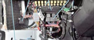
There is a fog lamp fuse installed in the niche of the instrument panel behind the mounting block:
Standard version of the brake light operating diagram
Power is supplied to fuse F17 from the battery, then the current goes to limit switch contact 11, and then, if the limit switch is closed, a circuit is formed with the filament of lamps 7. But note: part of the circuit is relay K1, more precisely, its contacts 5 and 4.
Basic network diagram
A complete electrical diagram with explanations of the VAZ-2112 car is here.
If the brake lights do not light up, on the VAZ-2112, as on all Tens, check one fuse. It is called F17 and is located in the mounting block to the left of the driver.
Main mounting block
It is important to know: voltage is always present at one of the fuse terminals. Check it out!
A few words about the “serviceability relay”
The lamp health relay is called K1, and it is the largest in the mounting block. If you remove this relay, then when you press the pedal you can dial the voltage at terminal 5 (but not 4). Look at the diagram again, and it will become clear what we are talking about.
The largest relay in the block
All relay contacts are numbered. Check the voltage at the block terminals:
- 6 – “mass” potential;
- 2 – voltage “+12”, but only after turning on the ignition;
- 5 – “+12” by pressing the pedal;
- 4 – the terminal rings like a ground tap.
If the potential “0” is not generated at terminal “4,” it means that the lamp filaments are burnt out or there is a break in the wiring. Now consider something else: the ground potential has been detected, but the lamps do not light. This is where suspicions of a short circuit arise.
Table of external connections and connectors of the VAZ-2110 mounting block.
| Block | № | Color | Electrical circuits |
| Ш1 | 1 | ZhCh | fog lamp (left) |
| 2 | GP | trunk lock motor, heated seats | |
| 3 | R | door lock relay | |
| 4 | ABOUT | power window relay | |
| 5 | ZhP | fog light relay | |
| 6 | AND | fog lamp (right) | |
| 7 | MS | power window relay | |
| 8 | — | reserve | |
| Ш2 | 1 | — | reserve |
| 2 | — | reserve | |
| 3 | — | reserve | |
| 4 | H | weight " - " | |
| 5 | ZhP | size (left rear) | |
| 6 | Warhead | outdoor light switch | |
| 7 | — | reserve | |
| 8 | ZhCh | license plate lamps, off instrument lighting | |
| 9 | KP | size (right rear) | |
| 10 | TO | size (right) | |
| 11 | ZhG | email windshield wiper motor, windshield wiper and washer switch. | |
| 12 | Z | outdoor light switch | |
| 13 | ABOUT | fog light switch | |
| 14 | Emergency | hazard switch | |
| 15 | — | reserve | |
| 16 | GP | Ignition switch (terminal 15), steering column switch | |
| 17 | R | windshield wiper and washer switch | |
| 18 | JV | steering column headlight switch | |
| 19 | — | reserve | |
| 20 | — | reserve | |
| 21 | AND | size (left) | |
| Ш3 | 1 | midrange | low beam (left headlight) |
| 2 | — | reserve | |
| 3 | WITH | low beam (right headlight) | |
| 4 | R | generator (cl. 30) | |
| 5 | TO | generator (cl. 30) | |
| 6 | TO | generator (cl. 30) | |
| Ш4 | 1 | PZ | on-board display system |
| 2 | GO | hazard switch | |
| 3 | IF | hazard switch | |
| 4 | H | weight " - " | |
| 5 | PG | portable lamp plug | |
| 6 | Salary | heated rear window switch, heated rear window lamp | |
| 7 | — | reserve | |
| 8 | — | reserve | |
| 9 | — | reserve | |
| 10 | ZhZ | steering column washer and windshield wiper switch | |
| 11 | B | email windshield wiper motor | |
| 12 | BW | steering column washer and windshield wiper switch | |
| 13 | GB | steering column switch, ignition switch lamp | |
| 14 | BP | brake lights, clock, interior lamp | |
| 15 | P | brake lights | |
| 16 | RP | off brake lights | |
| 17 | ABOUT | generator (cl. 30) | |
| Ш5 | 1 | AF | high beam (left lamp) |
| 2 | JV | rear window heating element | |
| 3 | G | heater controller, glove compartment lamp | |
| 4 | Z | high beam (right lamp) | |
| 5 | ZhG | Windshield wiper motor, SAUO recirculation valve | |
| 6 | PB | email cooling fan, beep |
Guides
- Car manuals, instructions, repair and operation manuals for cars 55 views
- BMW error codes 48 views
- Mercedes error codes 47 views
- VW Car Repair and Operation Manual 30 views
- Location of diagnostic OBD connector in FORD 29 views
- Toyota car repair and operation manual 27 views
- Repair and operation manual for Fiat cars 25 views
- Fuse and relay block Citroen Jumper, Fiat Ducato, Peugeot Boxer from 2006 to 2014 25 views
- Fuse and relay box Honda Civic from 2006 to 2011 24 views
- Mercedes car repair and operation manual 24 views
Features of connecting power windows
Unlike conventional mechanical devices, power windows are not equipped with traditional gear reducers, but with a special drum. The shaft of a DC electric motor is inserted into its hole located in the center. In this case, the motor is only a component of the gearmotor, on which, as we found out earlier, the speed and quality of raising and lowering the windows depends.
Before installing a new power window, you must select the correct device based on its technical characteristics, and also make sure that the product is in a fully folded state. Otherwise, you are unlikely to be able to install the product efficiently and ensure its flawless operation after connecting it to the vehicle’s on-board network.
You've probably noticed that on almost all foreign cars the power window buttons are duplicated on each car door. To connect additional ESP buttons in the doors, you need to run an additional three wires into each door.
Standard ESP connection diagram
Changed to this scheme (here without rear ESP)
Connection diagram for additional ESP button.
How the additional ESP button is made on Kalina
To install one duplicate button in the door you will need:
- 2x contact (plastic connector) block male + female 1 pair
- Large male terminals 2 pcs.
- Mom large 2 pcs.
- Mom little 7pcs
- Earth 1pc.
- Power window button 1 pc.
- Button installation cup 1 pc.
- Power window button connector 1 pc.
- Wire diameter 0.75 4 met.
- Door pistons 7pcs
If your ESP buttons have been moved to the doors. then the insert into the harness for additional buttons will look like this. The meaning is that we need to run 3 wires into each door:
- Ground (Ground, in theory, can be taken into the doors, but there is not always good contact there, so it is better to run a separate ground wire)
- +12V “after ignition” (with power window relay at ChYa)
- Button illumination (take it from the cigarette lighter, since it is in the middle between the doors.)
Disconnect the negative terminal from the battery.
We look for +12V on the ESP relay (black and white wire) to it and screw both of our red +12V
Then we climb through the door. There are 2 wires going to the ESP motor - gray and blue, through a connector. Unplug the connector:
We take 2 wires (I have black and black and white), of such length that we can reach from the original chip with the blue and gray wire going into the corrugated door to our future button. We crimp 2 large male terminals onto them and insert them into the connector. We put it on the chip with blue and gray going into the corrugated door, so that the black comes from the gray, and the black and white from the blue:
Insert the wires into the button connector:
- Red +12V
- Black mass
- White backlight
- Black with gray wire chips
- Black and white with blue wire chips
We crimp with small “mothers” and insert the ESP buttons into the connector. We do it according to the scheme:
- Red +12V to slot 2
- Black ground - in slot 5
- White backlight - in slot 4
- The black wire from the gray wire of the chip goes into slot 6
- Black and white from the blue wire chips - into slot 3 (THREE).
Don’t confuse the button connector sockets! That’s not all, we need two more short wires, through which we will now connect our button to the ESP motor, like we’ll do it as it was. For beauty, we take the same colors of wires that were attached to the original chip going to the door from corrugated material, i.e. black and black and white. It will be like a continuation of the original wires, and in the middle of them is our button. We insert the black wire into socket 1 of the button connector. Black and white - into socket 7. We crimp the other ends of these wires with large “mothers” and put the purchased connector on them so that when putting this on connector to the dangling chip going to the ESP motor:
- The black wire went to the gray ESP motor chips
- Black and white - to the blue wire of the ESP motor chip.
In principle, that's all. Don't pay attention to the orange wire in the photo - it's a mass for heating the mirrors.
You can use the button from Kalina. it is more beautiful and a little more expensive than the VAZ 2110.
Electrical circuits of cars VAZ 2110, VAZ 2111, VAZ 2112, repair
Why is repair needed?
You have to resort to window regulator repair for various reasons. And most often the cause of the malfunction lies in the electric motor. This is explained by the fact that the engine housing itself is not sealed and moisture can enter it. As a result, rust appears inside, which destroys the mechanisms. If the window regulator does not work on a VAZ 2114 or another model, it is recommended to start repairs by disassembling the door. But first, let's look at the types of lifts used today:
- rack and pinion windows, which are considered the most reliable of all others;
- Cable SPDs, which are installed standard on VAZ models;
- plank SPD.
Depending on which manufacturer produces ESPDs, they can be installed in standard locations without much modification. If they don't fit, then it's okay. The window regulator can be easily rebuilt. In addition to the fact that SPDs differ in type of design, they can also have different motors. Thus, an electric motor of domestic or imported production can be installed on window regulators. It is because of this that the difference arises between SPDs, which may have:
- different speeds of lowering and raising the windows;
- different noise levels during operation;
- ability to work in winter conditions, etc.
Electrical connection diagram for the ignition system of a Lada-Priora car
The spark ignition system wiring diagram section contains graphical information about the supply of current to the main automated instruments and the vehicle's electronic engine control system. From them, the voltage is distributed to the main blocks, power plants, as well as control sensors and ECUs.
| Contact no. | Decoding |
| 1 | ECU power supply |
| 2 | Connecting the ignition system harness to the dashboard harness |
| 3 | Fuse box |
| 4 | Measuring device for determining the speed of movement |
| 5 | Road roughness detection sensor (located on the shock absorber support cup) |
| 6 | Oil pressure warning light indicator |
| 7 | TPS sensor |
| 8 | DTOZh sensor |
| 9 | Coolant temperature indicator |
| 10 | MAF sensor (MAF sensor) |
| 11 | Idle air valve (IAC) |
| 12 | Main fuel pump relay |
| 13 | Power fuse for the fuel pump |
| 14 | Starter relay |
| 15 | Starter relay fuse (15A) |
| 16 | ECU fusible link |
| 17 | Crankshaft position sensor (CPS) |
| 18 | Oxygen sensor |
| 19 | Camshaft phase sensor |
| 20 | Knock Level Sensor |
| 21 | Solenoid valve for filter purge and vapor recovery |
| 22 | Lambda probe |
| 23 | Electronic ignition module power supply |
| 24 | Supplying voltage to spark plugs |
| 25 | Fuel injector power |
| 26 | Harness block from ignition coil to ECM harness |
| 27 | Harness block from the ignition system to the ignition coil wiring harness |
| 28 | Engine computer connector to injection system |
| 29 | Injection system harness block to ignition system harness |
| A | To terminal (+) AB |
| B1, B2 | Places for attaching ground wires of the ignition system |
| C1 | Place of attachment of the ground wire coming from the ignition coils |
Ignition system electrical harness, 2170-3724026.
Ignition coil electrical harness, 1118-3724148.
Injector electrical harness, 11186-3724036.
Malfunctions and their elimination
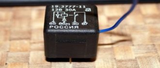
There are several ways to understand that something is wrong with the relay
First, pay attention to the frequency of the relay clicks. If one of the bulbs burns out, the relay will blink twice as fast
When there is no signal at all, then it is worth checking the wiring, perhaps this is the problem. The fuse could also be the culprit.
Troubleshooting must begin with the state of the electrical circuit. This is due to the fact that an oxidized contact or a short circuit leads to a lack of signal or increased voltage. Fuses and relays don't just blow out, so the problem is most often in the wiring. If everything is in order there, then change the fuse and, if necessary, the relay. This can be done by removing it from the brackets in the mounting block. Then we install a new part, and everything should work.
Design and diagram of the K-700, K-701 gearbox
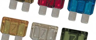
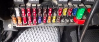
Each element is designed for a specific current. Its meaning is written on the case, but for convenience, the colors of the case correspond to certain values.
• Brown – 7.5 A • Red – 10 A • Blue – 15 A • Yellow – 20 A • White – 25 A
If the permissible current value is exceeded, the fuse blows and the circuit opens. In this way, consumer failure is prevented. The reason for the increase in current strength may be an increase in the circuit load or a short circuit. In this case, the total resistance of the circuit decreases, and the current increases.
Each element is designed for a specific current. Its meaning is written on the case, but for convenience, the colors of the case correspond to certain values.
- Brown – 7.5 A
- Red – 10 A;
- Blue – 15 A
- Yellow – 20 A;
- White – 25 A.
What is the fuse in the radio?
As a standard, this is a 20 ampere blade fuse marked with the English letter F and the number 4 (F4). According to the rules, each individual device is protected by an individual fuse, but this already applies to their, so to speak, personal protection (secondary).
Where is the fuse for the radio?
Where is the fuse for the radio?
The fuse responsible for the radio is located in the power circuit. If the head unit is connected through the cigarette lighter cables, then the safety insert of the blade type or cylindrical configuration is located in the installation box inside the instrument panel.
What fuse should be installed on the radio?
There is no need for a fuse in front of the radio, there is one in the radio - two fuses will perform one function (overload, or something else will happen in the radio itself), but next to the battery you need it (at least 15A) it will protect mainly from short circuits.
Where is the fuse for the radio on the VAZ 2114?
This fuse is located in the wiring box, which is located in a special block under the hood of the car. To access it, you need to remove the cover and find the desired part among many others. On most VAZ models it is located third from the bottom (in the left row) and is marked F7.
Where is the fuse located in the Pioneer radio?
The fuse is actually located on the back of the PCB not far from the RCA outputs.
How to remove a fuse in a car?
Classic “finger” fuses are installed between two elastic legs. To replace the “finger” fuse, you just need to pull it out from the space between the tabs, slightly pressing the movable tab (the second, as a rule, is rigidly fixed in the block). The new fuse is inserted in the same way.
Which fuse on the VAZ 2110 is responsible for the radio?
The VAZ radio fuse with a current of 20 A and marked F4 is located in the compartment on the right side of the steering mechanism. This element is responsible not only for the car radio, but also for the right fog lamp.
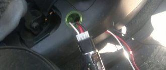
What wire is needed to power the radio?
It's easier, but not better. The positive wire must be copper, stranded and with a sufficiently large cross-section (from 4 mm2). Its length should be as short as possible. At a distance of at least 40 cm from the positive terminal of the battery, it is necessary to install an additional fuse with a rating of 10 to 20 A and good insulation.
How to connect the radio correctly so as not to drain the battery?
To avoid draining the battery, the radio is connected via the ignition switch. When the ignition is turned off, it is impossible to use the head unit. For switching, a supply wire protected with red insulation is used. An additional yellow cable leads directly to the battery terminal.
How to check the radio from the battery?
You need to find the wire that powers the contact group of the ignition switch and screw (solder) the red wire from the radio to it. The yellow wire is connected to the positive terminal of the battery (so that the settings are always stored in memory). The black wire is to ground, as usual.
Which fuse is responsible for the radio on the VAZ 2114?
This is where you need to look for the cause first. The fuse box socket – F4 – is responsible for the radio and cigarette lighter. The fuse marking in it should be 20A.
Where is the fuse for the starter on a VAZ 2114?
This block is located in the lower left part under the glove compartment on the center console. This block may differ in different modifications of the car. The location of the fuel pump fuse for VAZ 2114 and VAZ 2115 may also differ.
Where is the VAZ 2114 mounting block located?
Now regarding the location of the device. The unit itself in the VAZ 2114 injector is located in the engine compartment, opposite the instrument panel. To get to it, you don’t have to remove the instrument panel; just open the hood and look under the windshield on the driver’s side.
How to check the outputs on the radio?
If there is no sound, check the speakers, check the output, set the multimeter to 20 volts and check the voltage (there should be several volts and it should change constantly). but most likely the day off ims fucked up.
What is the fuse for in the radio?
Functions The radio fuse, located in the power circuit, is designed to protect the electronic components of the equipment from the consequences of short circuits. The device is a thin thread of low-melting metal, designed to carry a certain current value.