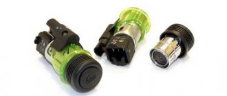
VAZ 2110 2111 2112 (Lada 110 111 112) - a family of cars produced in 1995, 1996, 1997, 1998, 1999, 2000, 2001, 2002, 2003, 2004, 2005, 2006, 2007, 2008 and 2009 with sedan and hatchback bodies and a station wagon mainly with 8 and 16 valve gasoline engines ( injector , carburetor). In this article you will find a description of the fuse and relay blocks of the VAZ 2110 2111 2112 with diagrams , photographs and their locations. Electrical connection diagram. Let's highlight the fuse responsible for the cigarette lighter.
The purpose of fuses and relays in your VAZ 2110 (2111 / 2112) relay may differ from those presented and depend on the year of manufacture. The current purpose can be printed on the block itself.
Main block
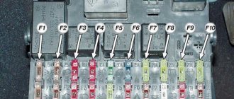
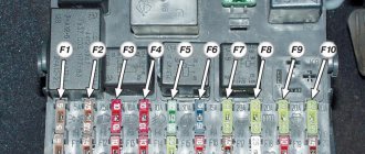
Layout of relays and fuses in the main mounting block.
| № | Purpose |
| K1 | Relay responsible for the operation of car lamps |
| K2 | Electric windshield wiper |
| K3 | A special relay that interrupts the turn lights when the hazard warning lights are activated |
| K4 | Low beam start |
| K5 | High beam launch |
| K6 | Space for installing an additional element |
| K7 | Starting the heated rear window |
| K8 | The VAZ 2110 model does not have this element. |
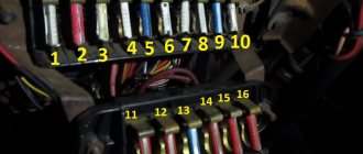
A visual indication of all fuses in the VAZ 2110 car.
Electromagnetic relays
To relieve the car switch contacts from high current consumption, electromagnetic relays are used in the electrical circuit. There are 8 of them in total:
- K1 is responsible for the serviceability of the lamps;
- for turning on the front window wiper - K2;
- for turn signals and hazard warning lights – K3;
- for low beam headlights - K4;
- for turning on the high beam - K5;
- for heating the rear window - K7;
- for fog lights located at the rear - K8.
The block contains relay K6, which is additional. Before installing a new element into the system, check the wiring for short circuits, otherwise the parting that is protected by the fuse element or the fuse itself may fail. The described block is the main one, but the only one in the VAZ-2112 electrical circuit.
Source
Where are the mounting and additional blocks located?
Location of the main mounting block in a VAZ 2110 car. In earlier versions, the black box was installed under the hood.
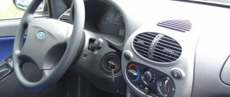
Finding these devices is easy. The main panel with the relay is located in the lower left corner of the steering wheel - near the driver’s left foot. You can remove it if necessary without additional materials. If you take out the mounting block, you will find another one behind it. But in domestic cars of this model range there are three of them:
- Main fuse block. Located in a convenient place - to the left of the steering wheel;
- Two additional panels. Located in the torpedo. One of them is located inside a niche behind the main block, the other is on the opposite part.
It is recommended that you examine each black box so that new fuses can be easily installed if necessary.
Why doesn't the cigarette lighter work?
The cigarette lighter consists of a metal cup with contact plates and a bimetallic retainer and an insert with an incandescent coil. Electric current flows through the heating element after pressing the insert. After heating to a given temperature, the bimetallic clamps lose their elasticity; the built-in spring pushes the insert away from the contact plates. The connection diagram includes an additional wire for the socket illumination lamp.
If the cigarette lighter in a VAZ-2112 does not work, then the cause of the malfunction is:
- burnt-out filament coil;
- oxidized or rusted contacts inside the cartridge;
- broken wiring harness;
- damage to the protective fuse.
Electromagnetic relays
To relieve the car switch contacts from high current consumption, electromagnetic relays are used in the electrical circuit. There are 8 of them in total:
- K1 is responsible for the serviceability of the lamps;
- for turning on the front window wiper - K2;
- for turn signals and hazard warning lights – K3;
- for low beam headlights - K4;
- for turning on the high beam - K5;
- for heating the rear window - K7;
- for fog lights located at the rear - K8.
The block contains relay K6, which is additional. Before installing a new element into the system, check the wiring for short circuits, otherwise the parting that is protected by the fuse element or the fuse itself may fail. The described block is the main one, but the only one in the VAZ-2112 electrical circuit.
To ensure safe and stable thermal conditions of an internal combustion engine, precise operation of the cooling system is required. The slightest failure will lead to overheating of the engine, which can lead to burnout of the head gasket or failure of the piston group elements.
Additional block
Location of the additional block with fuses and relays.
There is an additional block in the central panel, the location of which can be seen in the photo. It contains three fuses with the same power of 15A:
- The first is responsible for the controller and ignition module in the VAZ 2110.
- The second takes over the protection of the mass flow sensor (mass flow meter), purge valve, heating and speed sensor.
- The third is responsible for the injectors and fuel pump.
- The fourth number indicates an electric fan.
- Under the fifth is an electric fuel pump.
- The last relay relates to the ignition of the VAZ 2110.
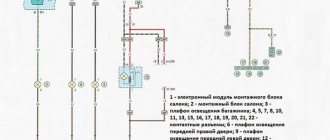
VAZ-2112 wiring diagram
Wiring diagram for a car in a hatchback body (click on the picture to enlarge)
Designations: 1 – Headlight, 2 – Horn, 3 – Main radiator fan, 4 – Starter, 5 – Battery, 6 – Generator, 7 – Gearbox limit switch (reverse), 8 – Actuator in the front passenger door, 9 – Relay power windows permissions, 10 – Starter relay, 11 – Heater fan, 12 – Electric heater partition drive, 13 – Main pump, 14 – Washer reservoir sensor, 15 – Driver’s door actuator, 16 – Front passenger window selector, 17 – Fifth wheel release button doors, 18 – Heater fan resistance unit, 19 – Main wiper motor, 20 – Driver's window lift selector, 21 – Front passenger's window lift motor, 22 – Central locking, 23 – Exterior light switch, 24 – Brake fluid leakage sensor, 25 – Additional pump , 26 – Driver's window lift motor, 27 – PTF on indicator, 28 – PTF switch, 29 – Dashboard , 30 – Heated glass on indicator, 31 – Heated glass switch, 32 – Steering column selector switch, 33 – PTF relay, 34 – Ignition switch , 35 – Main fuse block, 36 – Illumination of heater controls, 37 – Hazard warning button, 38 – Heater control controller, 39 – Glove compartment lighting, 40 – Glove compartment lid end cap, 41 – Cigarette lighter, 42 – BSK – display unit, 43 – Ashtray illumination, 44 – 12V socket, 45 – Instrument lighting switch, 46 – Actuator in the right rear door, 47 – Right rear passenger window selector, 48 – Clock, 49 – Right rear passenger window motor, 50 – Brake limit switch (closed – pedal is pressed), 51 – Left rear passenger window motor, 52 – Left rear passenger window selector, 53 – Actuator in the left rear door, 54 – Turn signal, 55 – Handbrake limit switch (closed – handbrake on), 56 – Rear wiper motor, 57 – Navigator’s lamp, 58 – Interior lamp, 59 – Temperature sensor in the heater, 60 – Limit switch for an open front door, 61 – Limit switch for an open rear door, 62 – Trunk lighting, 63 – Rear optics (on the body), 64 – Rear optics ( on the fifth door), 65 – License plate illumination.
Main settings
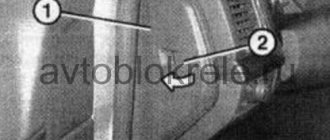
The fuse box is located under the decorative panel to the left of the steering column. Removing it is quite simple: press the latch and lower the structure down. Once you have access to the fuses, they can be removed and checked for integrity using a millimeter. The block contains only 20 fuses, designed for different current strengths. Just look at the color of the fuse to determine what amperage it is designed for:
- tan runs at 5 amps;
- darker brown – at 7.5;
- red – at current strength 10;
- saturated blue – at 15;
- bright yellow is for 20;
- colorless or transparent – by 25;
- green – by 30.
Source
Main settings
The fuse box is located under the decorative panel to the left of the steering column. Removing it is quite simple: press the latch and lower the structure down. Once you have access to the fuses, they can be removed and checked for integrity using a millimeter. The block contains only 20 fuses, designed for different current strengths. Just look at the color of the fuse to determine what amperage it is designed for:
- tan runs at 5 amps;
- darker brown – at 7.5;
- red – at current strength 10;
- saturated blue – at 15;
- bright yellow is for 20;
- colorless or transparent – by 25;
- green – by 30.
Procedure. Step-by-step instruction
If after completing the next step the problem goes away, further checks are stopped.
- Open the hood.
- Wait for the engine to cool down.
- Perform an initial visual inspection: integrity of the hoses, reliability of the clamps, absence of leaks or cracks.
- Make sure that the expander cover elements are in good condition. Remove scale, rust, clear holes, wipe, assemble. The absence of noticeable damage to parts gives hope that the product will work.
The valve design is elementary. The cover contains a spring. Functionally, it is designed to regulate the pressure in the cooling circuit. A hot engine increases it, a cold engine decreases it.
Compressing at a value of 1.1 atmospheres, the spring relieves excess pressure and prevents the destruction of hoses and the tank. As the motor cools, it creates a vacuum effect. The tank will begin to flatten. The valve equalizes the pressure.
The lid screws tightly on the thread, eliminating distortions. There should be a gap between it and the body. An overtightened valve will not work. It is difficult to test the device's operation in road conditions. You can check by replacing it with a known good one.
Inspect the electrical wiring elements to ensure a reliable connection
Possible factors for damage to electrical circuits:
- vibration;
- oxidation;
- burning;
- breakage, fraying of electrical wires;
- insulation aging, short circuit.
Switch the tester to resistance measurement mode. Remove it with special tweezers and ring the fuse link F7 located in the mounting block.
Replace the burnt-out element with a serviceable one with a rating of 20A. Inspect and clean the nest. Insert fuse.
It was not possible to find out the reason, the protection triggered again - look for a short circuit.
Disconnect the fan plug. Use a tester to measure the circuit of the electric motor windings. Zero resistance or a break indicate the need to replace the radiator blower electric drive.
Interturn short circuits that cause multiple replacements of fuse links cannot be measured with the device.
Sensor check
Start the car. Pull out the coolant temperature sensor connector. The fan starts working - the sensor needs to be replaced. Secure the disconnected wire. Drive to a nearby service station.
Relay test
There is a hatch on the floor at the front passenger's feet.
Below it is a built-in panel with three relays of the same type:
- fan installation;
- fuel pump;
- ignition (main thing).
By replacing each other, try to start the airflow. The VAZ 2110 fan does not work - go to the next step.
Where is the VAZ 2110 cooling fan relay located?
If you are wondering where the fan relay is located on a VAZ 2110, then this photo below will answer your question and you can easily find where the cooling fan relay is located on a VAZ 2110.
Check the electric motor
Winding measurements did not reveal a malfunction. Apply voltage briefly from the battery using additional insulated conductors. The operation of the fan indicates a malfunction of the controller, which does not output a signal to the relay.
- The only correct solution is to turn on the airflow directly and urgently visit a service station.
- Prevention of breakdowns of the cooling system of the VAZ 2110 injector 16 valves.
- Periodically inspect the components of the cooling system.
- Monitor the cooling temperature on the device, listen to the operation of the fan.
- Maintain coolant level. Replace after 2 years or 30,000 km.
- Use the solution to remove rust and scale.
- Signs of a change in the properties of the coolant are a change in color, an increase in fluidity.
- Check the density with a hydrometer.
- Do not mix coolants.
- Every twelve months, rinse the expansion tank cap with water and check it on a stand with a pressure gauge.
- Avoid contact of aggressive liquids with electrical wiring and electric motor windings.
Improvements to the fan start control circuit for the VAZ 2110 injector
The smooth functioning of the engine worries factory designers, auto mechanics, and car enthusiasts. Folk craftsmen change the design of valves and electrical circuits.
Installation of three position toggle switch:
- continuously on: the VAZ 2110 cooling fan does not work;
- constantly switched off: warming up the engine when starting in the cold season, automatic control is faulty;
- automatic mode: controlled by the controller, the equipment is working properly, the algorithm is executed correctly.
When choosing an installation location, consider the following conditions:
- prevent accidental switching;
- not to be confused with other controls.
It is important to remember when modifying the design about the safety of the changes made.
