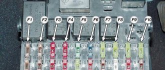
VAZ 2106 fuse box pinout, diagram
If you have any problems with electrical equipment: the low or high beams have disappeared or are not working, the turn signals, stove, cigarette lighter, fan, wipers are not working, the signal has disappeared, etc., then this could all be the reason that the fuse has blown. This means it needs to be replaced.
To do this, you need to know the location of the mounting block. And it is located under the steering wheel, on the left side. In order to understand what the VAZ 2106 fuses are responsible for, you need to look at the simple pinout of the old fuse block (FB) and see the description below.
Table “VAZ 2106 fuse designations”
| Fuse number | Current, A | What is he responsible for? |
| 1 | 16 | 1. Lamps 2. Horns 3. Power socket 4. Cigarette lighter 5. Rear lamps 6. Front door open warning lamps 7. Clock |
| 2 | 8 | 1. Windshield wiper and wiper relay 2. Wiper motor 3. Heater motor |
| 3 | 8 | Left headlight (high beam) and high beam indicator lamp |
| 4 | 8 | Right headlight (high beam) |
| 5 | 8 | Left headlight (low beam) |
| 6 | 8 | Right headlight (low beam) |
| 7 | 8 | 1. Left front marker 2. Right rear marker 3. Trunk light 4. License plate light 5. Instrument lights 6. Cigarette lighter light |
| 8 | 8 | 1. Right front marker 2. Left rear marker 3. License plate light 4. Engine compartment lamp 5. Side light indicator lamp |
| 9 | 8 | 1. Oil pressure sensor with warning lamp 2. Coolant temperature sensor 3. Fuel level with reserve warning lamp 4. Parking brake activation and brake fluid level warning lamps 5. Turn signals and corresponding warning lamps 6. Battery charge warning lamp 7. Control lamp carburetor choke control lamp 8. Carburetor shut-off valve 9. Tachometer 10. Reversing lamps 11. Glove compartment lamp 12. Rear window heating relay coil |
| 10 | 8 | 1. Voltage regulator. 2. Generator excitation winding |
| 11 | 8 | Spare |
| 12 | 8 | Spare |
| 13 | 8 | Spare |
| 14 | 16 | Heated rear window |
| 15 | 16 | Engine cooling fan |
| 16 | 8 | "Emergency" |
Not protected by fuses
- Starter
- Ignition system
- Battery charging circuit
- Low beam relay
- High beam relay
Thermobimetallic fuses
- Windshield wiper (since 1985) - integrated into the electric motor circuit
- Window lifters - integrated into the electric motor circuit
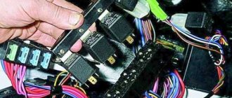
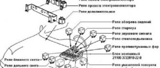
Relay
- Hazard warning and turn signal relay ('77-'85 - 23.3747
, '85-'01 -
231.3747
) - mounted on the front panel behind the instrument cluster. - Battery charge indicator lamp relay (PC 702) - secured to the right side member mudguard in the engine compartment with two self-tapping screws. A ground tip is installed under one of the screws.
- The low beam headlight relay - B
(113.3747, 90.3747 (RS 527)) - is mounted on the mudguard of the right side member in the engine compartment. - Headlight high beam relay - A
(113.3747, 90.3747 (RS 527)) - is mounted on the mudguard of the right side member in the engine compartment. - Windshield wiper relay (PC 514) - installed under the instrument panel on the driver's side and attached to the body with two screws.
- Voltage regulator (PP 380, RS 702, RS 121, 59.3702, 592.3702, 591.3702, 591.3702-01) - mounted on the mudguard of the left side member in the engine compartment.
- Sound signal relay (PC 528) - mounted on the mudguard of the left side member in the engine compartment.
- Cooling system fan relay (90.3747-10, 113.3747-10) - mounted on the left side member splash guard in the engine compartment. (not installed since 2000)
- Parking brake warning lamp relay (PC 492) - located behind the instrument panel. (Not applicable since 1994)
- Rear window heating relay - located behind the instrument panel.
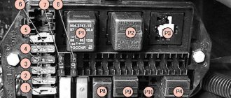
Relay VAZ 2106
The following shows the location and designation of each factory relay:
- Voltage regulator, which is responsible for proper charging of the battery. Located on the left mudguard.
Battery charge voltage regulator relay - Turning on the radiator cooling fan. It is also located on the left mudguard, behind the expansion tank.
Radiator fan relay - A light on the dashboard that indicates battery charging. The relay is already located on the right mudguard.
Battery charging light relay - Low and high beam headlights. They are also located on the right mudguard. They are identical and interchangeable.
Relay for low and high beam headlights - Turn and hazard warning relay. It is located behind the instrument panel, approximately behind the tachometer.
- The wiper relay is located on the left side, under the instrument panel.
The video below clearly shows where which relay is located.
VAZ 2107 - injector diagram (fuel injection control system)
| Relay/fuse no. | Designations |
| 1 | Controller connector |
| 2 | Mass air flow sensor |
| 3 | Coolant temperature sensor |
| 4 | Crankshaft position sensor |
| 5 | Throttle position sensor |
| 6 | Oxygen concentration sensor |
| 7 | Speed sensor |
| 8 | Ignition module |
| 9 | Canister purge solenoid valve |
| 10 | Electric fan relay |
| 11 | Electric fuel pump relay |
| 12 | Main relay |
| 13 | Fuse protecting the power circuit of the electric fuel pump relay |
| 14 | Fuse protecting the main relay power circuits |
| 15 | Fuse link |
| 16 | Fuse protecting the controller's constant power supply circuit |
| 17 | Diode |
| 18 | Idle speed control |
| 19 | Injectors |
| X1 | Diagnostic block |
| X2 | Connection block to the vehicle electrical system |
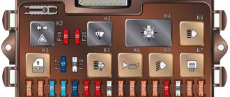
"Euroblock" VAZ 2106 (new model), diagram
Below is a picture of what the Eurobloc looks like in real life.
Photo of Euro block VAZ 2106
Below is the pinout of the new type of power supply or, as people say, “Euroblock”. The diagram also shows which fuse is responsible for what.
VAZ 2106 fuse block diagram with decoding
How to identify a blown fuse
- visual inspection;
- diagnostics with a multimeter.
Visual inspection
It is necessary to check the integrity of the metal partition of the element. If it is broken, then the insert is burned out.
Diagnostics with a control and a multimeter
When an element burns out, the integrity of the jumper is not always compromised. It wouldn't hurt to check with a multimeter. The probe is applied to the fuse, the device is turned on, and if it shows resistance other than 0 Ohm, then the element is broken.
Replacing the VAZ 2106 fuse box with a “Euroblock”
And finally, for those who don’t know how to replace the old model with a “Euroblock”, the following information. There is nothing complicated here.
You just need to follow the instructions below:
- First you need to disconnect the minus from the battery.
- Use a 10mm wrench to unscrew the old power supply. In this case, the wires are not disconnected.
- According to the diagram above, wires and jumpers are installed.
- It is important to install jumpers only on those wires that carry voltage from the engine compartment.
- Jumpers are installed between pins 3-4, 5-6, 7-8, 9-10, 11-12.
- Next, the wires are removed one by one from the old device and attached to the Euroblock.
- At the end, check that the connection is correct (for example, with the low beam on, if you pull out the 5th fuse, the left headlight should go out).
- All other circuits are also checked.
The video below clearly shows how to replace an old power supply with a Euroblock.
Removal and replacement process
There is nothing difficult in the process of changing power supply parts, so we will not describe this process. But we will tell you how to replace an old-style power supply with a new-style device.
- First of all, disconnect the battery. Now open the driver's door and use a screwdriver to pry out the two fasteners securing the decorative interior trim. Move it to the side and you will see a block. Using a Phillips screwdriver, unscrew the screws securing the power supply. Do this carefully so that the wires do not fly off the terminals in the process.
- Once the power supply is unscrewed, move it down. But do not pull it too hard to avoid breaking the wires. Note! Jumpers must be installed on those wires through which voltage comes from the engine compartment. Do not connect the jumper after the fuse itself, otherwise this will result in voltage passing through one part to power several electrical components.
- The order of installation of jumpers should be as follows: 3-4, 5-6, 7-8, 9-10, 11-12, 12-13.
- Now you need to remove each wire one by one, starting with the first fuse from the old power supply, and mount it on the new one. Perform this operation with each contact, until the very last wire. When all the contacts are in place, you should check whether you did everything correctly. In particular, you need to turn on the voltage source and remove the corresponding fuse. If the device stops functioning, then all actions were performed correctly. For example, turn on the low beam headlights and remove one of the power supply elements responsible for the left or right headlight. If it goes out, then you did everything right.
- Check each fuse in the same way. If, when dismantling the element, the device continues to work, then the jumper is most likely installed incorrectly, so double-check the connection diagram.
This completes the replacement of the power supply with a new type device. As you can see, there is nothing difficult about this, but if you are not sure that you will do everything correctly or cannot distinguish the blue wire from the red or green, then entrust this matter to an electrician.
Sources
- https://granta-service.ru/diagnostika/predohraniteli-vaz-2106-kakoj-i-za-chto-otvechaet.html
- https://vsepredohraniteli.ru/lada/vaz-2106.html
- https://knigaproavto.ru/shemy/vaz/21032106/496-predohraniteli-vaz-2106.html
- https://rus-avtomir.ru/predohraniteli/rele-vaz-2106
- https://saturn-lada.ru/novosti/raspinovka-predohranitelej-vaz-2106.html
- https://bumper.guru/klassicheskie-modeli-vaz/elektrooborudovanie/predohraniteli-vaz-2106.html
- https://VazNeTaz.ru/publ/remont_vaz_samomu/predoxraniteli-vaz-2106-sxemy-kakoj-za-chto-otvechaet.html
Problems with the mounting block and their solution
Many owners of "sixes" are faced with the problem of frequent power surges. It can be caused either by a malfunction of the generator or voltage regulator, or by problems with the mounting block. If you have established that it is the cause of the problems, do not rush to replace it with a similar one, just a new one. Better take a closer look at the mounting block from GAZ-3110. How is it better? The fact that it will allow installing fuses on the VAZ-2106, which are equipped with “installers” of modern cars. They are easier to buy and more reliable. In addition, the Volga mounting block is much more compact than the “six” one. It is made in the form of a single strip, accommodating only 12 fuse links.
Modifications
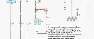
Switching diagram for electric windows of the front doors
1 - main fuse block; 2 — relay for turning on electric windows; 3 — left door power window switch; 4 — right door power window switch; 5 — gear motor for the right door electric window; 6 — gear motor for electric window lifter of the left door; 7 - additional fuse block; 8 — ignition switch; A - to terminal “30” of the generator; B - to the instrument lighting switch; B - conventional numbering of plugs in the gear motor block.
Carburetor solenoid valve control circuit
1 - ignition switch; 2 - generator; 3 - battery; 4 — ignition coil; 5 - switch; 6 — control unit; 7 — carburetor solenoid valve; 8 — carburetor limit switch.
Engine cooling fan motor
1 - generator; 2 - battery; 3 — ignition switch; 4 - main fuse block; 5 — electric fan activation relay, 6 — electric fan activation sensor; 7 — electric fan; 8 - additional fuse block