Modifications of mounting blocks and fuses of the VAZ 2112 have changed more than once during the production of the model. Radical innovations were introduced only in 2002 after the appearance of a 16-valve injector.
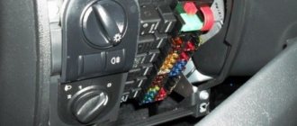
In 2006, there was only one unit in the cabin, and in 2007 a console unit was added to it. This happened thanks to changes in the shield and gearbox, and the addition of a Europanel. The cover of the main unit became hinged, which simplified access to the fusible elements. Separate inserts outside the mounting blocks, for example, under the brake pad, have been preserved.
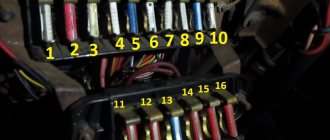
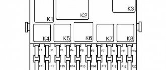
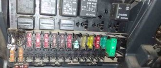
VAZ 2112 fuse diagram
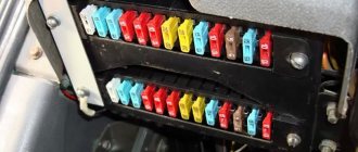
With an 8-valve and 16-valve engine, it is equipped with a main mounting block, and since 2008 an additional console has been added. A diagram with element markings is printed on the left side of the main block cover and placed below.
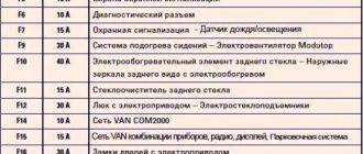
The designations of all elements are presented below. You can find the transcript in the table.
| Circuit breakers | Power, A | What protects |
| F1 | 5 | Lamps for turning on the license plate lighting, instruments, side lights, trunk, left side. |
| F2 | 7,5 | Low beam |
| F3 | 10 | Further |
| F4 | 10 | PTF |
| F5 | 30 | Door windows |
| F6 | 15 | Portable lamp (socket) |
| F7 | 20 | Engine cooling fan. Sound signal. |
| F8 | 20 | Rear window heating element. Relay for turning on the heated rear window. |
| F9 | 20 | Recirculation valve. Cleaners, windshield and headlight washers (wiper fuse). Relay for turning on the heated rear window. |
| F10 | 20 | Spare |
| F11 | 5 | Starboard side marker lamps |
| F12 | 7,5 | Middle left |
| F13 | 10 | Far left. Power indicator lamp |
| F14 | 10 | Left PTF |
| F15 | 20 | Electrically heated seats. Trunk lock lock |
| F16 | 10 | Turn signals and emergency lights. |
| F17 | 7,5 | Interior lighting. Ignition switch. Stop signal. Watch. |
| F18 | 25 | Glove compartment lighting. Heater controller. Cigarette lighter fuse. |
| F19 | 10 | Locking door locks. Relay for monitoring the serviceability of brake light lamps and dimensions. Direction indicators. Reversing light. Generator excitation winding. On-board control system display unit. Instrument cluster. Watch. |
| F20 | 7,5 | Rear fog lamps. |
Relay
- K1 - lamp health monitoring;
- K2 - windshield wiper;
- KZ - direction indicators and emergency lights;
- K4 - switch on low beam;
- K5 - high beam;
- K6 - additional relay;
- K7 — heated rear window;
- K8 - rear PTF.
Starter fuse and relay
Installed on the device itself between the engine and the fan radiator. If signs of a malfunction appear, it is better not to delay replacing the element and install a new relay.
Fuel pump fuse and relay
Located in the additional interior installer - No. 3. Responsible for the fuel pump relay No. 5.
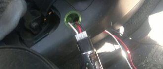
Relay and fuse for cigarette lighter
No. F18 is rated at 25 Amps.
Stove
The 25 A element F18 is responsible for protecting the operation of the electrical circuit of the heater motor.
Turn signals
The elements are marked as F19 and are rated at 10 Amps.
Brake lights
Located in the main block - No. F17. Its power is 7.5 A.
Where is the alarm fuse located?
No. F16 and rated 10 A.
Cooling Fan
The F7 element with a power of 20 Amperes is responsible for its protection.
Which fuse goes to the radio?
This is an F4 rated at 20 A.
Window lifters
F5 at 30 A.
Fuse and relay for central locking VAZ 2112: where is it located
They can be found in a separate box behind the main mounting block.
Ignition
The main relay is located in the additional cabin unit, where it is number 6.
Reverse
F19 with a rating of 10 Amperes is responsible for the lamps.
Fogs
Protected by three inserts: right - F4, left - F14, and rear - F20. The power of all PTFs is 10 Amps. In case of tuning, you may need to replace them with new ones along with the fog lights. The connection occurs via switch K8.
Lamp health monitoring relay
Marked as K1 in the main block of the VAZ 2112.
Brake
Installed under the brake pedal.
Relay and fuse for injectors
The additional element F3 is rated at 15 Amps.
Fuse for interior light
The F17 element with a power of 7.5 A is responsible for the safe operation of the VAZ 2112 interior lighting lamp.
Number plate illumination
Corresponds to F1 with a rating of 5 Amps.
Generator
A three-level relay voltage regulator is located on the device. It is better to replace the factory element with a new one, since three-level voltage regulation often leads to a short circuit.
Heated rear window
Relay K7 is responsible for turning on. Protects the F8 electrical circuit with a rating of 20 Amps.
Seat heating
It is protected by a 20 Amp F15 insert.
Wiper relay
This is a K2 and without its stable operation there will be no washer supply to the windshield, and the wipers will not be able to do their job.
Charger
They placed it next to the device - one of the few elements of this kind under the hood of a car.
Low and high beam VAZ 2112
It is protected by fuses F2 and F12 (left and right headlights), and the high beam is protected by F3 and F13 (left and right). The first has a rating of 7.5 A, and the second has a rating of 10 A.
Fuse for the dashboard of VAZ 2112
Located in the wiring harness leading to the instrument panel from the battery.
Dimensions
There are 2 fusible elements - F1 and F11, left and right. The power of both is 5 Amperes. Factory fuses require replacement due to the fact that the dimensions often burn out due to their malfunctions.
Heated seats
It is protected by an element marked F15 for 20 Amperes.
VAZ 2112 speedometer fuse: where is it located?
He's gone.
Opening the trunk
This is an F1 and is rated at 5A.
Fuse F6
Responsible for protection against burnout of the car socket. Its rating is 15 Amperes.
VAZ 2112: fuse F17 blows
Most often, this element, which is responsible for interior lighting, fails due to a battery failure. Its power is 7.5 A.
Fuse F19
Responsible for protecting the brake light, reversing lights and dimensions.
Relay K1
An element of lamp serviceability, which in older versions is replaced by a jumper.
Relay K6
This is a reserve item.
Speed sensor
Located on the wiring harness leading to the device.
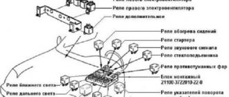
Location
The relay and fuse mounting block is located on the left side of the steering column in the instrument panel.
Types of mounting blocks
Block 2110-3722010
Block 2110-3722010-01
Block 2110-3722010-08
Where is the fuse box
A separate section of the chain is protected by a special element.
The current strength is calculated for certain values. Due to a short circuit in the cigarette lighter, this parameter may be outside the acceptable range. To prevent wire melting or fire, a thin metal bridge in the fuse blows. Therefore, replacement with a working element is required. Evidence that the fuse on the VAZ has blown will be the failure of not only the cigarette lighter, but also additional devices. This element is part of the circuit going to the stove, radio and glove compartment lamp. If all these devices fail, you should get to the mounting block and replace them.
Relay
K1
- Lamp integrity monitoring relay (4412.3747 / 2110-3747410)
K2
- Windshield wiper relay breaker (524.3747 / 2110-3747710)
K3
- Relay-breaker for direction indicators and hazard warning lights (492.3747 / 2108-3747010-02)
K4
- Relay for low beam headlights (113.3747 / 2105-3747210-10)
K5
- Headlight high beam relay (113.3747 / 2105-3747210-10)
K6
- Additional relay (71.3747-01 / 2110-3747310-01)
K7
- Relay for turning on the heated rear window (113.3747 / 2105-3747210-10)
K8
- Rear fog lamp relay (113.3747 / 2105-3747210-10)
Fuse blown
Sometimes the device does not need to be replaced. It is enough to change the fuse located inside the device itself. The procedure is carried out as follows.
- Open the hood and remove the negative terminal from the battery. You can also remove the fuse from the mounting block that is responsible for the cigarette lighter of the VAZ 2110.
- We unscrew the four fasteners of the tunnel covering and remove both parts of the lining.
- Disconnect the three-pin plug going to the cigarette lighter.
- Remove the lining under the handbrake lever.
- Remove the gearshift lever cover.
- We move the seats back, and then unscrew the three fastenings of the upper part of the tunnel and remove it.
- Pull out the cartridge.
- Use a flat-head screwdriver to pry the cigarette lighter latch so that it comes out of the seat.
- We remove the nest from the cladding for subsequent repairs.
Inside the cigarette lighter is a miniature mica plate. It is a semiconductor that sometimes breaks and melts. It needs to be removed. After this, it is worth assembling the unit and then checking the functionality of the device.
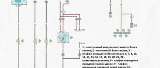
Additional mounting block Priora
- F1 (15 A) – main relay and starter interlock circuit fuse;
- F2 (7.5 A) – fuse for the power supply circuit of the ECU (controller);
- F3 (15 A) – Priora fuel pump fuse;
- K1 – main relay;
- K2 is the place where the Priora fuel pump relay is located.
Attention!
The relay and fuse diagram may differ depending on the configuration and production date of the vehicle. Current diagrams of the mounting block are presented in the operating manual for the date of manufacture of the vehicle ().
Let us remind you that on our website you can find detailed instructions for repairing the Lada Priora with your own hands.
Keywords: Lada Priora mounting block | Lada Priora torpedo
8 6 0 2 2 1
Share on social networks:
How to protect yourself from serious malfunctions
The traffic rules provide a list of breakdowns with which it is prohibited to operate a car. These include non-working wipers, headlights not working, and no turn signals. Driving a car with the listed breakdowns is dangerous. A car that is unable to communicate to other road users that it intends to turn can cause a serious accident with its sudden maneuver. Without working wipers, it is impossible to ensure maximum visibility of the road, which will also lead to an accident, the cost of which is often too high. The presence of a set of replaceable fuses in the car will help to instantly eliminate the malfunction and will allow you to operate the car without posing a threat to all road users.
It is important to remember that replacing a blown fuse with a new one can only be done by observing the specified ampere value. It is this indicator that is responsible for the amount of current allowed for a particular section of the circuit. It is also unacceptable to install electronic or electromechanical fuses instead of fuses.
Basic starter malfunctions
The traction relay does not operate after the ignition key has been turned, and the armature does not rotate.
In this situation, it may be due to the following possible problems:
- the battery is broken or discharged, the solution to this problem is to buy a new battery or charge it;
- the positive contacts have oxidized - you just need to clean them;
- it happens that an interturn short circuit occurs on the winding of the traction relay - to correct this situation, you need to install a new relay;
- the circuit that powers the traction relay has broken - you need to check the wires for integrity, and whether they have become disconnected from the circuit?
- contacts “30” and “50” do not close - you just need to change the contact part of the ignition switch;
- The traction relay armature does not work well - you need to remove it and disassemble it, there may be a lubrication problem.
After turning the key, the starter does not start, the armature rotates slowly, and a click is heard in the traction relay.
This situation may arise due to previously similar situations:
- the battery is discharged or disconnected - you need to check and correct the situation;
- the winding of the traction relay is shorted or broken - you also just need to change the relay;
- the ends of the wires have seriously succumbed to oxidation - they need to be checked and cleaned, starting with the battery.
After turning the key, the starter armature spins, but the flywheel does not spin..
This situation arose due to the fact that:
- the freewheel is slipping - you need to diagnose the starter at the stand and replace the clutch if it is faulty;
- The gears on the gearbox are worn out - you just need to replace them.
The starter makes a lot of noise when the armature is spinning.
This problem arose because:
- The liners on the armature or drive shaft bearings have served their service life - you just need to replace the parts that have failed;
- the starter is not secured properly, and the cover could have broken - you just need to secure it or change it;
- the gears on the gearbox, flywheel crown or drive have failed - you just need to change them, or immediately replace the non-functioning parts entirely.
- the gear is constantly engaged with the flywheel; if the clutch on the shaft splines is stuck, it is possible that the armature of the traction relay is stuck - to solve this problem, you need to lubricate the splines with oil. And if the traction relay is stuck, then you need to either change it or use certain methods to get rid of the jam.
Replacing the VAZ 2110 starter relay on your own
All drivers know that without a starter, the car not only won’t move, it won’t even start. It drives the crankshaft. In this case, the shaft is accelerated to a certain frequency. As soon as the desired frequency is reached, the engine will start. One of the starter components is a two-winding traction relay. Replacing the VAZ 2110 starter relay is a mandatory procedure, because without the correct operation of this mechanism, the vehicle will not move. On a VAZ 2110, replacing the starter relay can be done on your own.
Lada 2110 PhiX › Logbook › Additional, starter unloading relay VAZ 2110
Hi all! I’ll tell you about a very useful modification that will be useful for owners of elderly VAZ 2110. Many ten-year-olds have encountered a problem when, in hot weather, a hot engine does not respond to the movement of the key. The starter does not turn and you have to go under the hood with a screwdriver and make a direct connection to the contacts. In the case when the starter is working (in my case it is completely new), the culprit for this trouble may be the contact group of the ignition switch. Over time, the contact group in the ignition switch wears out or the current collector contacts burn out. This problem is successfully solved by installing an additional unloading relay. By the way, such a relay is installed on many cars from the factory.
To install this relay we will need: 4-pin relay with a metal ear (30-40A); 80r Wires 1.5 sq. mm; about three meters -80r relay block - 1 piece; 20r Flat male connector - 1 piece; Flat female connector - 1 piece; Ring tips - 2 pcs. Electrical tape, heat shrink, corrugation.
Let's put this whole thing together according to the following scheme.
The relay needs to be protected from moisture, for this I used thick heat shrink, in which I completely covered the relay block.
After assembly, I check the relay by connecting it to the LBP.
Pay attention to the laboratory power supply, the ammeter shows the current that the relay consumes. The current is only 0.12A and it is this current that will flow through the contact group of the ignition switch. For comparison, the pull-in current according to different sources is from 10 to 30A! Most often we are talking about 20-25A, where 20A is the current of the pull-in winding and 5 amperes of the holding winding.
Obviously, such currents will not be to the liking of the ignition switch contact group. The relay solves this problem perfectly.
I carried out another experiment, turned the voltage towards a decrease, the relay operates down to 7V, at 6V it no longer works, but this is quite enough, because the retractor will not work even at 8 volts.
We connect the wiring to the starter.
We pull off the red wire from the flat terminal of the traction relay and tightly insert the “folder” with the wire from the new relay into the connector of this wire. This wire now powers the coil of the new relay. We connect wires with ring lugs to the battery terminals.
We put the wire from contact 30 of the new relay with the “mother” onto the freed contact of the traction relay. Through this wire, the plus goes to the traction relay coil.
You can install the starter relay on the VAZ 2110 yourself
Those people who have a VAZ 2110 have certainly encountered a situation where the starter did not turn after the key was turned, and some clicks are heard, which indicate that the retractor relay is working. In such a situation, the question immediately arises: where is the VAZ 2110 starter relay located and how to find it faster. This question is also relevant when tuning a VAZ 2111.
But we have interesting news for you: the VAZ 2110 simply does not have a starter relay. There is a solenoid relay, to which the positive contact is supplied from the ignition switch. The relay is installed on the starter, its size is 2 times smaller than that of the starter, and it is round in shape.
Next, we will highlight some popular malfunctions that usually arise in the VAZ 2110, related to the VAZ 2110 starter relay and the starter; by the way, a lot of things are used in the VAZ 2115, so by tuning this car, many problems can be avoided.
Replacing the fuse
One of the most common causes of breakdown is failure of the protective element. A clue that the fuse for the cigarette lighter has blown will be a non-working VAZ 2110 stove or a faulty glove compartment illumination lamp. To carry out repairs, it is necessary to replace the blown fuse in the mounting block.
To get to the box, press the button in the front panel to the left of the steering wheel. The fuse to be checked is number F18, rated for a current of 25 amperes. It is convenient to use tweezers for replacement.
A fuse of the recommended rating should be installed. Otherwise, there is a high risk of insulation melting, short circuit, and fire. After repair, you cannot connect powerful devices to the cigarette lighter socket. The maximum power is 300 watts. Calculated using the formula P=I*A, where I is the network voltage (12 volts), and A is the amperage (25 amperes).
Additional fuses and relays
Location
Additional fuses and relays are installed behind the side trim of the console, secured with two screws, on the right side of the instrument panel.
Circuit breakers
1 (15A)
- Ignition module
- Controller
2 (15A)
- Canister purge valve
- Vehicle speed sensor
- Oxygen sensor (heating)
- Air flow sensor
3 (15A)
- Fuel pump relay
- Fuel pump
- Injectors.