Peugeot Partner is a compact van, designed on the basis of a passenger car, produced since 1996. The first generation was supplied to the market in 1997, 1998, 1999, 2000, 2001, 2002, 2003, 2004, 2005, 2006 and 2007. During this time it received 2 restylings. After a complete update, the 2nd generation was produced in 2008, 2009, 2010, 2011, 2012, 2013, 2014, 2015, 2016 and to date in various modifications (tepee, with an extended and standard base, etc.). We offer information on the diagrams of all fuse and relay blocks of the Peugeot Partner with a detailed description of the elements for all generations, we will show the fuse responsible for the cigarette lighter and the instruction manual.
In this model there are 2 main places with the location of
fuse blocks :
- on the left under the dashboard (under the cover)
- in the engine compartment (near the battery under the protective cover).
Removal and replacement instructions
The replacement process is the same in both the first and second blocks, but in order not to confuse anything, we will describe the replacement in each of them separately.
Under the dashboard
Finding the unit located in the cabin is not difficult. It is conveniently located and immediately visible. There is no need to remove any nodes or systems to access it.
Preparation
To replace the safety elements, simply remove the cover. In addition, to avoid accidentally damaging the elements and getting an electric shock, special plastic tweezers are provided. Perform work on removing and installing elements only with it. It's convenient and safe.
In the store, buy a set of fuses for a Peugeot Partner car. In general, many people recommend taking it in the car.
Steps
- To access the unit, located on the left side of the driver under the dashboard, you need to perform a fairly simple operation.
- We find the clamps located on the cover.
- We turn them a quarter turn.
- Remove the cover.
- In the table we find the number of the fuse responsible for the faulty equipment.
- Next, according to the diagram, we find where in the compartment the element responsible for the non-working consumer is located.
- We remove it with tweezers.
- We install a new one, similar to the nominal value.
- Turn the ignition key.
- We check whether the consumer has started working.
- If it works, close the lid.
Table of elements
Layout diagram
In the engine compartment
It is not difficult to find the unit installed in the engine compartment; it is located next to the battery and is covered with a plastic cover, which can be gray or black.
Preparation
Before starting work, turn off the car. Make sure you have spare tweezers and protectors on hand.
Replacement fuse tweezers
Steps
- Raise the hood.
- We are fixing this.
- We find where the block is.
- Release the latches and remove the cover.
- We look at the table. We determine the number of the fuse that protects the inactive consumer.
- Find a place on the diagram.
- Stop it with tweezers and remove it.
- We put the same one in place of the extracted one.
- We check if the consumer is working.
- If everything is ok, close the lid. If not, then most likely there is a hardware problem and this is where you will need to fix it. Wiring may also be damaged.
Table of elements
Layout diagram
Recommendations for use
- Before starting work, be sure to turn off the ignition.
- Disconnect the negative terminal of the battery.
- Exchange only for an item of equal value. In this case, the use of various wires and jumpers is strictly prohibited.
- Remove and install elements using tweezers.
- Replacement of high-power MAXI elements with additional protection should only be carried out by CITROEN service specialists.
Loading …
Description for 1st generation
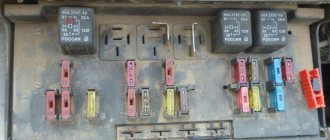
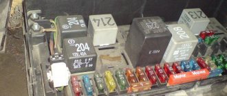
Fuse box under the hood
Lock position
Real photo of the unit
General scheme
Descriptive table
| № | Protection circuit | |
| one | 10 A | Reversing light, preheating unit, clutch release contact |
| 2 | 15 A | Fuel pump |
| 3 | 10 A | Electronic control unit (ECU) of the ABS system |
| 4 | 10 A | The engine control unit |
| 5 | 10 A | Replacement |
| 6 | 15 A | Front fog lights |
| 7 | 20 A | Headlight washers |
| 8 | 20 A | Engine ECU, fan relay |
| 9 | 15 A | Left low beam lamp |
| 10 | 15 A | Right low beam lamp |
| 11 | 10 A | Left high beam lamp |
| 12 | 10 A | Right high beam lamp |
| thirteen | 15 A | Sound signal |
| 14 | 10 A | Window cleaner |
| 15 | 30 A | Engine sensors |
| sixteen | 30 A | Air pump |
| 17 | 30 A | Wipers |
| 18 | 40 A | Electric fan for air conditioning system |
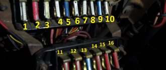
Partner passenger compartment fuse box
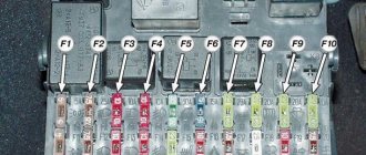
Scheme
Decryption table
| № | Protection circuit |
| F1 | Windshield washer 15A (with hinged doors), 12V socket (Modutop) |
| F4 | Dashboard car radio 20A, display, COM2000 |
| F5 | 15A Alarm Siren |
| F6 | Diagnostic connector 10A Citroen Berlingo |
| F7 | 15A Anti-theft |
| F9 | Heated seats 30A, electric fan Modtop |
| F10 | 40A Heated rear window, heated exterior mirrors |
| F11 | 15A Clean rear window |
| F12 | 30A electric sunroof, electric windows Citroen Berlingo |
| F14 | 10A VAN COM2000 network |
| F15 | VAN 15A network instrument panel, radio, display |
| F16 | Electric locks 30A |
| F20 | 10A Right rear brake light |
| F21 | 15A Rear left brake light |
| F22 | Citroen Berlingo 20A cigarette lighter fuse, 12V socket, electric door mirrors, interior lighting, directional light for reading maps and documents |
Fuses No. 1 and 22 are responsible for the cigarette lighter.
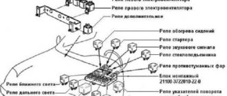
Fuse/relay box
Fuse/relay box in engine compartment
- 1. Battery case
- 2. Cover
- 5. Casing
- 8. Fuse box
- 9. Lock
- 11. Cover
- 13. Fuse
- 14. Fuse box
- 15. Fuse
- 20. Relay
- 50. Plug
- 51. Plug
- 52. Rivet
- 70. Flange nut
Under-dash fuse/relay box location (left-hand drive models)
- Under-Dash Fuse/Relay Box (BSI1)
Circuit breakers
| Circuit breakers | Sample | Nutrition | Application |
| F1 | 15 A | "+BAT" | Rear wiper |
| F2 | — | — | — |
| F3 | 5 A | +APC | Airbag control unit |
| F4 | 10 A | +APC | Diagnostic connector |
| Manual air conditioning system | |||
| Diesel fuel additive supply pump | |||
| Rear view mirror adjustment mechanism | |||
| Mechanism for adjusting the height of the headlight beam | |||
| F5 | 30 A | +BAT | Front door windows |
| F6 | 30 A | +BAT | Locks |
| F7 | 5 A | + ACC | Lighting lamps |
| Lighting: Cooled glove box | |||
| Mirror | |||
| Lamp lighting | |||
| Multifunctional roof | |||
| F8 | 20 A | +BAT | Multifunction display |
| Car radio RNEG | |||
| Car radio RD4 | |||
| CD changer | |||
| Tire pressure detection system | |||
| Hazard/anti-theft alarm | |||
| BSR: Towbar switching unit | |||
| BTC: Body transformation block | |||
| F9 | 30 A | + ACC | Cigarette lighter |
| 12 V socket in luggage compartment | |||
| Front 12V socket | |||
| F10 | 15 A | +BAT | Switch module under the steering wheel |
| F11 | 15 A | +BAT | Anti-theft switch |
| F12 | 15 A | +BAT | Rain sensor and outdoor lighting brightness |
| Airbag | |||
| BSR: Towbar switching unit | |||
| BTC: Body transformation block | |||
| F13 | 5 A | +BAT | Engine System Interface Unit (Module 2) |
| Dashboard | |||
| F14 | 15 A | +BAT | Hands free bluetooth kit |
| Parking sensor control unit | |||
| Automatic air conditioning control panel | |||
| F15 | 30 A | +BAT | Locking/unlocking locks |
| F16 | Shunt | +BAT | — |
| F17 | 40 A | +BAT | Heated rear window |
| Electrically heated rear view mirrors |
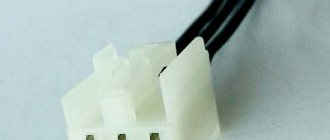
Connectors
| Number | Connector | Number of contacts | Color | Name |
| 2 | E.P. | 40 | Black | Main electronics wiring harness |
| 3 | E.A. | 6 | Black | Auxiliary Wiring Harness |
| 4 | PP | 16 | Green | Main power harness |
| 5 | P.B. | 10 | Black | Instrument panel power cable |
| 6 | PB1 | 10 | White | Instrument panel power cable |
| 7 | AP | 2 | Grey | Power Wiring Harness |
| 8 | PH2 | 16 | Grey | Power to interior wiring harness |
| 9 | PH1 | 16 | Black | Interior power wiring harness |
| 10 | EH2 | 40 | Blue | Interior electronics wiring harness |
| 11 | EH1 | 40 | White | Interior electronics wiring harness |
EP connector
EA connector
PP connector
PB connector
Connector PB1
AP connector
| Contacts | Contact type | Signal |
| 1 | Exit | Powered by + battery |
| 2 | Exit | Powered by + battery |
PH2 connector
| Contacts | Contact type | Signal |
| 1 | Exit | Power supply + auxiliary consumers (1st key position) (Portable lamp - 12 V connector, rear) |
| 2 | Exit | Power from the “+ battery” is turned off in parking mode to operate the security alarm |
| 3 | Exit | Power supply “+CAN” (rain sensor) |
| 4 | Exit | Power “+CAN” (Dashboard) |
| 5 | — | Not connected |
| 6 | Exit | Power + after turning on the ignition (2nd key position) (Headlight adjustment knob - Rear view mirror selection mechanism) |
| 7 | Exit | Heated exterior mirror control |
| 8 | Exit | Power supply - Locking drives |
| 9 | Exit | Front window regulator |
| 10 | — | Not connected |
| 11 | Exit | +CAN - Airbags |
| 12 | Exit | Illuminated control panel for exterior rear view mirrors |
| 13 | Exit | Locking control (rear and front) |
| 14 | Exit | Rear lock control |
| 15 | Exit | Controls the unlocking of all vehicle locks (inside and outside) |
| 16 | Exit | Front lock control |
Connector PH1
Connector EH2
Connector EH1
Models with left-hand steering column
Attention: Comply with safety and cleanliness requirements. When disconnecting, ensure that the electrical connectors are properly unlocked. When connecting, ensure correct installation and fastening of electrical harnesses. The connectors must be disconnected without removing the wire harnesses from the connectors. Do not pull on electrical harnesses.
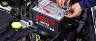
Removal
1. Disconnect the wires from the battery.
2. Disconnect the fastenings of the side trim of the instrument panel (1) (“a”) using a special tool.
3. Remove the side trim of the instrument panel (1).
4. Disconnect the sound insulation clips (2) under the dashboard (“b”) using a special tool.
5. Remove the trim (2) under the dashboard.
6. Remove the bolt (3).
7. Unscrew the nut (4).
8. Unfasten the front pillar trim (5) using a special tool.
9. Remove the front pillar trim (5).
10. Remove the bolt (6).
11. Unfasten the trim panel (7) (“c”) using a special tool.
12. Remove the trim panel (7).
13. Remove the screw (8) of the instrument panel (9).
14. Disconnect and move aside the Breakout Interface Interface (BSI) connectors (“d”) (10).
15. Disconnect the BSI (10) (“e”).
16. Move aside the instrument panel (9).
17. Slide the BSI (10) (as indicated by arrows “g”, “f”).
18. Disconnect and move aside the Connectors (“h”) of the Breakout Interface Intelligent (BSI) (10).
19. Move aside the instrument panel (9).
20. Remove the Smart Switch Box (10) (as shown by arrow).
Installation
1. Connect the connectors.
2. Install the smart switch box (10).
3. Install in reverse order.
4. Connect the wires to the battery.
5. Check the functionality of the electrical equipment.
Models with right-hand drive
Attention: Comply with safety and cleanliness requirements. When disconnecting, ensure that the electrical connectors are properly unlocked. When connecting, ensure correct installation and fastening of electrical harnesses. The connectors must be disconnected without removing the wire harnesses from the connectors. Do not pull on electrical harnesses.
Removal
1. Disconnect the wires from the battery.
2. Remove the miscellaneous drawer on the right.
3. Disconnect the connectors (“a”) of the Breakout Interface Intelligent (BSI) (1).
4. Break off the fastening tabs (2) of the smart switch box support (1) by bending them (“b”).
Note: Assemble the broken fastening tabs (2).
5. Slide the Breakout Interface (BSI) (1) (as indicated by arrows “c”, “d”).
6. Remove the smart junction box (1).
Where is the Peugeot Partner Tipi starter relay located?
Hello. There was a problem, in the morning I sat down to start it, and in response there was silence, all the devices work, dimensions, near, far, but the starter does not respond to the key, I removed at least the 5th terminal from the battery, installed another one, nothing changed, started it with a push immediately and without problems, warmed it up, drove for half an hour, turned it off, everything is still the same, there are no smart electricians in the area, make an appointment for the OD a week in advance.
I have no ideas. What about you? PLEASE. Look at the starter fuse (100 A). If the fuse is intact, then check the wire connection to the starter. If everything is intact, then most likely the starter is burned out.
Look at the starter fuse (100 A). If the fuse is intact, then check the wire connection to the starter. If everything is intact, then most likely the starter is burned out.
Are you sure that the fuse is 100A for the starter? As far as I understand. The starter, at the time of starting (especially in winter), draws starting current from the battery up to 460A. The starter is most likely “alive”; you need to look at the solenoid relay and the signal going to it. First of all, check the fuse under the black cover next to the battery—for a diesel engine it’s F8.. If an additional alarm is installed, then there is also a chance that it is this that does not remove the signal blocking to the retractor. Well, I repeat once again - if you have little understanding of electrics, then it’s better to go to a service center (why go straight to the OD - go to a crowded place - let them look, if there is a small thing (fuse, relay..) let them replace it and drive on, but if they give a verdict that is the end of the starter or something else “significant”, then ML = YES, and it’s not a fact that they will recognize it as an insured event.. Good luck
Source