Car : VAZ-2112. Asks : Smirnov Ivan. The essence of the question : I can’t find the fuel pump relay for the VAZ-2112?
Good afternoon, my gas pump has stopped pumping. When I turn the key, nothing happens. I think there is something wrong with the electrical system. Can you please tell me how to find the fuel pump relay?
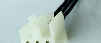
Pinout BN VAZ 2113, 2114, 2115
— block headlights; — gearmotors for headlight cleaners*; - fog lights*; — ambient temperature sensor; - sound signals; — engine compartment lamp switch; — electric motor of the engine cooling system fan; — generator; — low oil level indicator sensor; — washer fluid level sensor; — front brake pad wear sensor; — wire tips connected to the common windshield washer pump**; — windshield washer pump; — headlight washer pump*; — wire ends for connecting to the rear window washer pump on VAZ-2113 and VAZ-2114 cars; — low oil pressure indicator sensor; — engine compartment lighting lamp; — wire lug for connecting to the wiring harness of the engine control system; — gear motor for windshield wiper; — starter; — a block connected to the wiring harness of the ignition system on carburetor cars; — coolant temperature indicator sensor; — reversing light switch; — low brake fluid level indicator sensor; - accumulator battery; — low coolant level indicator sensor; — relay for turning on fog lights; - mounting block; — brake light switch; — plug socket for a portable lamp; — hydrocorrector scale illumination lamp; — switch for the parking brake indicator lamp; — block for connecting a backlight lamp; — switch for instrument lighting lamps; - Understeering's shifter; - hazard warning switch; — front seat heating element relay; — ignition switch; — rear fog light circuit fuse; - fuse for the front seat heating elements; — door lock circuit fuse; — front ashtray illumination lamp; — ignition relay; - cigarette lighter; — glove box lighting lamp; — switch for the glove compartment lighting lamp; — heater fan electric motor; — additional resistor for the heater electric motor; — heater fan switch; - heater switch illumination lamp; — lamp for illuminating the heater levers; — gear motors for electric windows of the front doors; — power window switch for the right front door (located in the right door); — gear motors for locking front door locks; — wires for connecting to the right front speaker; — gearmotors for locking rear doors; — wires for connecting to the right rear speaker; — door lock control unit; — wires for connection to radio equipment; — headlight cleaner switch*; — rear window heating element switch; — relay for turning on the rear fog lights; — block for connection to the heating element of the right front seat; — rear fog light switch; — switch for the heating element of the right front seat; — fog light switch*; — switch for external lighting lamps; — left front seat heating element switch; — block for connection to the heating element of the left front seat; — wires for connecting to the left front speaker; — power window switch for the left front door (located in the left door); — power window switch for the right front door (located in the left door); — wires for connecting to the left rear speaker; — side direction indicators; — courtesy light switches on the front door pillars; — courtesy light switches on the rear door pillars; - lampshade; — ceiling lamp for individual interior lighting; — block for connecting to the wiring harness of the electric fuel pump; — trunk light switch; — instrument cluster; — trunk lighting lamp; — display unit of the on-board control system; - trip computer*; — block for connecting the wiring harness of the engine control system; — rear exterior lights; — rear interior lights; — pads for connecting to the rear window heating element; — license plate lights; — additional brake signal located on the spoiler.
Relay-breaker layout diagram
| Name | What is it responsible for/what does it provide? |
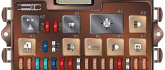
| K 1 | Relay for controlling the operation of lamps and lighting devices |
| K2 | Windshield wiper |
| K 3 | Hazard alarms, turn signals |
| K 4 | B S (low beam) |
| K5 | D Light |
| K 6 | Reserved relay |
| K 7 | Heated rear window |
| K 8 | Reserved relay |
Fuel check valve
The electric fuel pump of the VAZ “Ten” has good performance, but it creates too much pressure in the fuel system. In order to bring the pressure back to normal, a VAZ 2110 fuel pump valve is built into the fuel line; it is located in the “outlet” fitting of the BN housing. On the “tens”, a pressure regulator is also installed, which is located behind the fuel rail.
A valve malfunction involves a ball sticking in the open position, and the fuel pressure in the system may drop to zero. If such a problem occurs, the car is very difficult to start, since all the gasoline from the fuel lines goes back into the gas tank when the ignition is turned off. Is it possible to somehow repair the valve?
Drivers of 2110 cars claim that you can try knocking on the fitting in the BN flask so that the shut-off ball falls into place. If the malfunction cannot be eliminated in this way, the electric fuel pump bulb must be replaced, since this housing itself is non-separable.
Malfunctions
There are two main reasons why an alternator stops charging properly.
| Cause | Peculiarities |
| Device overload | This happens to those who like to install numerous additional equipment that is powered by a generator, that is, it requires electricity. These could be speakers, electric pumps, video devices, etc. A standard generator is not designed for such loads, and therefore loses efficiency |
| Battery and alternator mismatch | To ensure the operation of electrical equipment additionally installed on the car, many decide to install a more powerful battery with a standard generator. A mismatch in power leads to the fact that the generator ceases to provide proper charging to the more powerful battery. So he simply does not have enough resources for this |
What charge does the generator produce?
Many people are interested in the question of how much a generator should produce for normal operation.
Here the parameters directly depend on the current state of the car.
- If the engine is cold and just turns on, then the voltage will normally be 14.1-14.4 Volts;
- If you check the voltage after long trips in traffic jams, then the generator will produce less, about 13.9-14.1V.
Fuel pump relay VAZ 2110 injector 8 valves where is it located
Dear visitors of the site “Everything about cars”! We will be very grateful for your comments on the video clip “Where is the fuel pump relay for VAZ 2110 injector 8 valves?”, registration is not required for this. We also ask you to let us know if you have any problems playing the video.
thank you for the detailed video, the question has arisen about replacing the fuel pump mesh, and as a young driver it was very helpful
08/12/2017 — 21:05 Smouk65
Tell me what is the button to the right of the keys that blinks red?
05.08.2017 — 05:25 oipm pmpm
please tell me, my pump is humming, will replacing the mesh help? or is it better to change the pump?
03.08.2017 — 20:20 Slava Kazak
Or you can change the float and track separately, otherwise on my top ten it’s like you can’t start a car, so the device shows different fuel levels.
07/18/2017 — 04:25 SteFan
I accidentally poured about 1.5 liters of water into the tank, what should I do? The fuel pump is not working, how to drain the water.
07/12/2017 — 16:22 Boris Grishin
Well done. Everything is clearly intelligible.
07/11/2017 — 04:13 Alexander Suvorov
Thanks for the video Please make a video about replacing the fuel pump
06.23.2017 — 19:19 Ivan Dadykin
Is this an old-style fuel module? I watched another video on replacement, the modules are slightly different.
06/09/2017 — 20:45 MIKHAIL TROFIMOV
During disassembly, I tore off the thread on the fuel pipe, or rather the first two turns. When reassembling in the reverse order, the fuel pipe does not tighten completely. I started the car, the fuel pump pumps gasoline from under the tube, nothing oozes. What do you recommend if you don’t change the handset?
06.06.2017 — 07:43 malytino
Great educational video. Well done author. It may really be useful for novice drivers.
05/09/2017 — 07:38 taksist komandir
Instead of a rubber seal, you can wind a thread, it holds well and does not leak
04/28/2017 — 13:13 Sergey Sergeev
03/30/2017 — 11:02 Yuri Zotov
everything is clear and correct remark about the battery and ring gaskets, pressure relief
03/28/2017 — 20:08 Hicks Aliens
Damn the grid is dirty, what do you fill the tank with, brother?
04.03.2017 — 20:43 Soslan Bekoev
Good afternoon. Please tell me. I have a problem with the Kalina 8 valve. When the temperature rises above 90, the engine will not start until the pressure drops. Diagnostics showed nothing. The valves have been adjusted. Traction and engine operation without problems. but only up to 90 degrees
02/27/2017 — 21:38 Evgesha
Please tell me. What kind of O-rings should I buy from the store for tubes? In our stores they don’t know what sizes they are.
02/18/2017 — 15:39 Long Project
Thank you very much for the video. I have trouble starting when it sits, apparently the pressure will drop. If I turn it off and start it, everything is fine, I’ll try to change the grid, because gasoline is such a waste right now
01/24/2017 — 01:23 BEST MOVIE IN HD
Well done. explained everything perfectly
01/08/2017 — 05:39 craniosex Nekroman
Good evening, due to poor eyesight, before I took out the fuel pump, I broke the same long tube that you unscrewed with the 17th key. What should I do now?
01.01.2017 — 10:20 Ivan Rysev
good evening, but I couldn’t put on the container that is located under the fuel pump, is there any danger?
Causes: fuse, relay, connector
The pump power circuit includes many elements: closed relay contacts 5, fuse 3 (15 A), “+” wire, “pump-to-ground” wire. The most difficult defect is a short circuit of the “+” wire to ground. By the way, the cord itself is laid on metal, so such a defect cannot be ruled out.
Both the relay and the fuse are located in a block located under the dashboard on the right. A fuse can blow in two cases:
- The “+” cord makes contact with ground;
- The motor resistance decreases due to overheating.
The first defect may be “floating”, and then it will be difficult to identify. But before calling an electrician, try checking everything else:
- Relay 5 should click twice: when the ignition is turned on and after 1.5 s. If this does not happen, replace the relay;
- Check fuse 3. If it is blown, you need to look for the cause.
Consider the situation: the relay is working, but the fuse is blown. Then we do this: disconnect the pump connector, install a new fuse and measure the voltage at the terminals. Details are below.
Signs of a fuel pump failure
A faulty fuel pump is quite easy to identify, since it is characterized by characteristic signs of failure. For example: while driving, the car suddenly stalls - after turning it on again, the engine begins to make uncharacteristic sounds, while the starter does not stop turning. After the car starts up, the picture repeats itself - the fourteenth engine stalls again. It is also possible that the car starts every once in a while - problems usually arise after sitting at neutral speed.
Let's determine the most typical signs of a fuel pump malfunction:
- The engine refuses to start. Of course, there can be many reasons for this problem - the same spark plugs, or the ECU, but the possibility of a fuel pump malfunction is also worth taking into account;
- The pressure level in the fuel relay differs from normal values;
- The motor is tripping. As a rule, if the fuel pump does not pump as it should, the engine begins to twitch quite noticeably because gasoline is not burned properly in the working cylinders;
- The engine growls at low speeds. One of the most truthful signs, which indicates either an immediate breakdown of the pump, or that the low-purity filter is clogged and the mesh needs to be replaced.
There are quite a lot of possible breakdowns that could cause the fuel pump to fail. The following parts of the unit design can present an unexpected surprise: fuse, fuel pump relay, ground, electric motor, contact system. Let's look at each of them separately.
Pressure level
In order to get most of the picture of what is happening, it is enough to measure the pressure in the fuel rail. For this, it is necessary to use a pressure gauge that has a small measurement range (preferably up to 7 atmospheres), since devices with a large range can produce significant inaccuracies.
Rail pressure measurement
Under the hood of the fourteenth there is a pressure fitting; unscrew its cap and connect the pressure gauge to it.
Normal indicators should be as follows:
- When the engine is idling – 2.5 kPa;
- At the moment of ignition - 3 kPa;
- With a pinched drain hose – 7 kPa;
- When gaining speed - 2.5-3 kPa.
If the pressure gauge needle does not move when the ignition is turned on, then the gasoline pressure regulator is most likely broken. When there is no change as the speed increases, the fuel pump itself has failed, but if the needle moves very slowly, which indicates that the pump is pumping, but poorly, the fuel pump screen is clogged.
How to test wiring with a multimeter
If the fuel pump does not work, do not rush to change it - perhaps the problem is in poor-quality wiring. There are 3 wires connected to the pump: to the gasoline level sensor, and positive and negative to power the motor.
No special tools are required to check the wiring - a regular 12-volt light bulb is enough. We connect the light bulb to the negative and positive wires of the pump, and turn on the car’s ignition - if the light blinks, then everything is fine with the wiring.
Fuel pump motor
When you have determined that the external wiring of the fuel pump is normal, you need to move on to checking the motor. This is done with the same light bulb, the wires of which are connected to the external terminals of the motor. If the light comes on when you turn on the ignition, then you need to change the motor.
Fuel pump ground and relay
In the fourteenth, the mass of the fuel pump is fixed under the dashboard, next to the handbrake lever, during use of which the mass can be touched and shifted from its normal position. To fix this, remove the plastic around the handbrake, clean the ground contacts and reattach it.
Next to the ground there is a VAZ 2114 fuel pump relay. The relay is necessary so that during ignition the required pressure level is immediately created in the system.
A few words about where the fuel pump relay is located: after removing the plastic around the handbrake, you will immediately find 3 different relays - one of them is from the fuel pump.
Troubleshooting
Lack of charging can be caused by a wide range of reasons, which we will talk about today.
These reasons include:
- Weak contacts;
- Winding breaks;
- Short circuit on the rotor housing;
- Interturn short circuits;
- Mechanical breakdowns;
- Closing the positive clamp on the body;
- Short circuit in the phase winding;
- Short circuit of the stator to the housing.
Let's look at these situations in more detail to determine the true cause of the breakdown specifically in your case.
Start by turning off all additional equipment in your car that is not included as standard - DVR, navigator, audio system, etc.
Next, we perform the following operations.
- Measure the current output when the vehicle is cold, not running and all life support systems are disconnected. If there is no return at all, that's good. But this rarely happens. Almost always on tens there may be insufficient contact, some kind of short circuit, due to which there is recoil, but it is small. It’s much worse if the recoil is impressive and leads to battery discharge in one night spent in a parking lot or garage.
- If everything is normal, there are no strong current leaks or they are insignificant, and the battery has retained its charge, then you can return all the devices to the places that were installed additionally.
- Recheck the recoil. If at the same time the instruments show an active leak, then the reason does not lie in the battery and is not related to the generator. The culprit of the problem is one of the additionally connected devices.
- If no recoil is observed, then you need to carefully inspect the generator.
- There are many sources of trouble that can lead to generator failure. These include:
- Insufficient contact between the rotor rings and brushes;
- There was a break in the excitation winding;
- An interturn short circuit has occurred on the field winding coil. In this case, the generator will hum and get very hot;
- The field winding closes to the rotor housing;
- The stator shorts to the housing;
- A break occurs in the stator phase winding;
- The diodes have broken through in the rectifier block, that is, the diode bridge;
- The plus is shorted on the body;
- Mechanical problems have occurred.
Next, we will take a closer look at each of the reasons presented above.
Disassembled unit
Problem solving
- Poor contact. Loose contact can occur due to contamination, oil getting on the brushes, slip rings. Also, contact may deteriorate due to shrinkage of the springs that press on the brushes, or the brushes are stuck. Such phenomena lead to an increase in excitation resistance and can sometimes break the circuit. To eliminate the problem, sometimes it is enough to simply treat the surfaces with a rag soaked in gasoline. If the brushes are worn out, it is better to replace them. At the same time, check the condition of the springs and rings. The rings oxidize, so treat them with glass sandpaper.
- The winding has broken. If this happens, the battery will no longer charge. To determine the problem, place your hand on the battery. If there is a break, the device will begin to heat up. If you want a more accurate check, then disconnect the end of the field winding from the brush and connect the battery wires to it and terminal Ш using a voltmeter or a light bulb. If there is a break, the lamp will not light up and the voltmeter needle will not budge. Test each coil individually to determine which one is preventing the alternator from working. The internal coils must be replaced, and the internal coils must be soldered.
Unit diagram
- Short circuit between turns. An interturn short circuit can occur in any field winding coil. If such a situation occurs, the winding will begin to heat up, and the excitation current will increase. To check, be sure to measure the resistance of each coil. For this you will need a voltmeter.
- Short circuit on the rotor housing. Such a breakdown leads to the fact that the entire field winding is short-circuited. The generator stops working. The most common short circuit area is where the ends of the winding lead to the rotor rings. To check, use a 220V light bulb. One wire should be connected to any contact of the ring, and the second to the rotor core or shaft. If there is a short circuit, then the light will turn on. It is impossible to operate a car with such a generator. It is necessary to isolate or completely replace the faulty winding. The first option is only suitable for getting to a service station and carrying out a full repair.
- Short circuit on phase winding. This kind of problem occurs because the insulation between the turns of the stator coil is destroyed. If this happens, the generator will start to get very hot, the battery will not receive sufficient charge, as this happens at high crankshaft speeds.
- Short circuit of the stator to the housing. As is the case with the other listed short circuit options, in this situation the generator begins to overheat, hum, and its power drops significantly. To check you will need a 220V light bulb. One wire is connected to the core, and the second to the winding terminal. Any. If there is a short circuit, your light bulb will light up. To fix the problem, simply replace the failed coil.
- The positive terminal closes to the housing. This kind of malfunction is unpleasant because it does not just overheat your generator. Also, due to this short circuit, breakdown of the diodes of the rectifier unit occurs. From there, the problem goes to the battery, which can simply short out. Not infrequently, a short circuit led to complete failure of the battery. Although most often it just completely discharges.
- Mechanical problems. If we take into account all possible mechanical problems of the generator, then belt stretching will be in first place in terms of frequency. This is the most common breakdown in the case of the VAZ 2110. If this happens, the pulley will begin to seriously overheat and the battery will not have enough charge. It is not superfluous to check the quality of all contacts, the presence of broken connections and other possible mechanical problems.
If problems are detected with the generator, you should immediately begin measures aimed at eliminating the breakdown. If you have no experience, contact only trusted service stations.
The alternator is the heart of your vehicle's electrical system. Like the main human organ, it provides power to all instruments and devices. Therefore, you should treat it very carefully and if problems arise, do not delay repairs.
Where is the fuse and fuel pump relay on the VAZ 2110
It’s worth saying right away that the fuse and relay for the VAZ 2110 injector fuel pump are located in the same place. They are both located in the center console on the passenger side below. The main task of a relay in an electrical circuit is to close and open a circuit. Thanks to this, the circuit is protected from high inrush current.
| F1 - 5A | License plate lamps. Instrument lighting lamps. Side light indicator lamp. Trunk light. Left side marker lamps. |
| F2 - 7.5A | Left headlight (low beam). |
| F3 - 10A | Left headlight (high beam). |
| F4 - 10A | Right fog lamp. |
| F5 - 30A | Electric door window motors. |
| F6 - 15A | Portable lamp. |
| F7 - 20A | Engine cooling fan electric motor. Sound signal. |
| F8 - 20A | Rear window heating element. Relay (contacts) for turning on the heated rear window. |
| F9 - 20A | Recirculation valve. Windshield and headlight cleaners and washers. Relay (coil) for switching on the heated rear window. |
| F10 - 20A | Spare. |
| F11 - 5A | Starboard side marker lamps. |
| F12 - 7.5A | Right headlight (low beam). |
| F13 - 10A | Right headlight (high beam). Indicator lamp for turning on the high beam. |
| F14 - 10A | Left fog lamp. |
| F15 - 20A | Electrically heated seats. Locking the trunk lock. |
| F16 - 10A | Relay-breaker for direction indicators and hazard warning lights (in hazard warning mode). Hazard warning lamp. |
| F17 - 7.5A | Interior lighting lamp. Individual backlight lamp. Ignition switch illumination lamp. Brake light bulbs. Clock (or trip computer). |
| F18 - 25A | Glove box lighting lamp. Heater controller. Cigarette lighter. |
| F19 - 10A | Locking door locks. Relay for monitoring the health of brake light lamps and side lights. Direction indicators with warning lamps. Reversing lamps. Generator excitation winding. On-board control system display unit. Instrument cluster. Clock (or trip computer). |
| F20 - 7.5A | Rear fog lamps. |
| K1 | relay for monitoring the health of light bulbs; |
| K2 | front wiper relay; |
| K3 | repeater and alarm relay interrupter; |
| K4 | low beam relay; |
| K5 | high beam relay; |
| K6 | additional relay; |
| K7 | rear window heating relay; |
| K8 | backup relay |
A similar type of relay is installed on the fuel pump, protecting the circuit when the engine starts. It consists of a plastic housing that houses an electromagnetic coil with a core. The incoming voltage allows the core contacts to close. The operating current of the relay is 30 Amperes.
Where is the fuel pump relay located on a VAZ 2110?
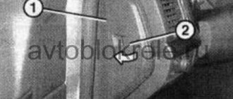
People often wonder where the fuel pump relay is located on a VAZ 2110; this photo will help you answer this question ↓
Where is the fuel pump relay located on a VAZ 2110?
Location of the relay and fuse for the fuel pump VAZ 2110 injector
If during repairs or diagnostics, the fault indicates a relay and fuse, then they must be removed and replaced with new parts. You should prepare a Phillips screwdriver and position yourself on the passenger side. At the bottom of the center console there is a cover secured with two screws. You need to unscrew them. It is there that the panel is located where the VAZ 2110 injector fuel pump relay is located and where the fuse for the VAZ 2110 fuel pump is located.
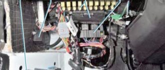
Rice. 2 Removing the side cover
After removing the protective cover, access to the power fuses and relays of the car appears. The required parts responsible for the operation of the fuel pump are marked with numbers 5 and 2 in the center of the photograph.
Fig.3 Power fuses and relays
Why does the VAZ 2110 fuel pump fuse blow out?
Fuse failure is a fairly common occurrence. Burnout indicates one thing - there is a short circuit in the fuel pump power system. In this case, you can change the fuse, drive away for several days without problems, and the situation will repeat again. So it is necessary to look for the reason.
The most common culprits are:
- the wiring harness above the exhaust manifold melted;
- wires under the carpet are damaged or melted;
- interturn short circuit in the pump motor;
- The positive wire going to the pump is damaged (current leakage to ground).
To identify the cause, you should disconnect the power supply from the fuel pump and turn on the ignition. If the fuse is blown, then the problem is in the wiring. Remained intact - short circuit in the electric motor. In the first case, you have to inspect the entire harness, looking for contact of the “plus” with the ground. As a rule, this is a gray wire running from the relay to the tank. The harness runs along the central tunnel, and not from the left threshold.
Finding the fuel pump relay and troubleshooting
As you know, in order to start any process, be it mechanical or electrical, you need a source of energy. And the relay thus represents a kind of trigger mechanism, because its work is to connect the contacts located inside, which close when exposed to electric current.
If we personally consider the VAZ-2112 fuel pump relay, then there are certain specifics in its operation. It also happens that many car enthusiasts simply do not know where exactly this relay is located, and how to correct the malfunction when it fails.
Principle of operation
Almost all relays that are mounted on Russian cars are identical. For the most part, they differ in the number of contacts with five versus four, and the latter, as a rule, does not have a central input.
The current strength, measured in Amperes, is also almost the same and is about 30 - 40A.
The relay in the photo is 30 Ampere.
The relay is connected to the network using a plastic block (plug - approx.), and when the electric current reaches the coil inside the relay and the magnetization process begins, it then closes and the circuit is connected.
Relay in additional fuse box
Location of the additional relay unit inside the car
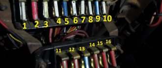
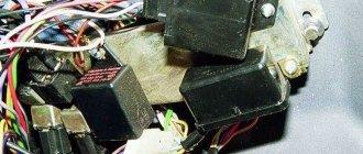
The fuel pump relay is located on the left side of the front passenger's feet, where three relays and three fuses are located next to each other.
After dismantling, we put it aside
The fuel pump relay is located exactly in the middle under the number “ 5 ”. Nearby, there is also a fuse numbered “ 3 ”.
Functionality check
In order to check the fuel pump fuse, you just need to inspect it and, if necessary, replace it with a known working one.
There are several methods to check the fuel pump relay:
- The easiest way is to replace the old relay with a known good one .
- If you don’t have one at hand, you can use a regular multimeter .
If everything has been checked, but the fuel pump does not work - article numbers
In general, the pump article number for VAZ-2112 engines looks like this: 21102-1139009-XX. Instead of the letters XX there are numbers, for example 02 or 03. They indicate the manufacturer. So, modules from different factories are not interchangeable! The resistance of the FLS resistor is different in them. However, when replacing the FLS sensor, you can borrow it from the “old” module. That's what they usually do.
Until April 2002, article numbers of the type 2112-1139009 were used.
Almost every module available for purchase contains a built-in pressure regulator. There are also exceptions - KSZC-A243, for example. The meaning is as follows:
- All internal combustion engines with a volume of 1.5 liters are equipped with a ramp with an “external” regulator (2112-1160010);
- The 21124 or 21114 motor requires a built-in regulator.
In conjunction with 1.5 liter engines, you can use any module – both with and without a built-in regulator.
Designations of analogues
- 21102-062213.0XX – instead of the letters XX there will be a plant designation (07, 13, etc.);
- KSZC-A233 or A243 – KSZC brand. There is no pressure regulator.
Location and principle of operation
ATTENTION! A completely simple way to reduce fuel consumption has been found! Don't believe me? An auto mechanic with 15 years of experience also didn’t believe it until he tried it. And now he saves 35,000 rubles a year on gasoline! Read more"
The location of the relay cannot be the same for all car models. This is directly related to the design of the machine, its make and model. However, in most cases, this is the area near the ICU (injection control unit) or under the dashboard, near the mounting block. On injection cars, the relay is usually installed in the driver’s left foot area, under the dashboard.
What is a relay for?
Above we talked about the microcontroller system. It is worth noting that the output of the ECU does not allow direct connection of a powerful load. And the fuel pump, which is based on a DC motor, has quite a lot of power. And when it is turned on, a significant current consumption occurs. But if you turn on the VAZ 2110 fuel pump relay coil from the control unit, the injector will continue to operate in the same mode, and no excess current consumption will be observed.
Therefore, we conclude: a relay is a buffer cascade between the electronic control unit and the current consumer. However, most relays have precisely this purpose - they allow a very weak current to flow in the control circuit. In this case, the entire electrical system of the car is divided into two parts:
- Low-current control circuits.
- Power cables (connecting optics, fluid and fuel pumps, power windows).
The VAZ 2110 fuel pump relay is located on the right side, opposite the front passenger seat. There is an additional block designed for installing some elements of electrical equipment. It is quite possible that such a simple solution was caused by the reluctance of the designers to use other fuse blocks that would be very different from those installed on carburetor engines.
Where is the fuel pump relay located on a 16-valve injection VAZ-2112
Car : VAZ-2112. Asks : Smirnov Ivan. The essence of the question : I can’t find the fuel pump relay for the VAZ-2112?
Good afternoon, my gas pump has stopped pumping. When I turn the key, nothing happens. I think there is something wrong with the electrical system. Can you please tell me how to find the fuel pump relay?
The fuel pump relay does not turn on.
If the fuel pump does not work, then first of all you need to check the attraction of the main relay and the fuel pump relay. If the main relay does not click, then it is necessary to check its switching circuit and its serviceability. How to do this is described in the article the main relay does not turn on,
In the case when the main relay turns on, but the fuel pump relay does not, it is necessary to check the power at pins 85 and 86. When using a test lamp, its current consumption should not exceed 0.25A, otherwise damage to the controller may occur. If the control lamp does not light up on any terminal, then the relay is not receiving power. This may be caused by a blown fuse or a broken power cord.
In the case when the lamp burns brightly on one terminal, and at half-glow on the second, and the relay may be activated, you should remove the relay from the socket and connect terminals 85 and 86 with a test lamp. When the ignition is turned on, the control lamp should light up and go out after approximately 20 - 30 seconds. If the lamp lights up and there is poor contact in the connection between the block and the fuel pump relay. If the lamp does not light up, there may be a break in the wire connecting the relay to the controller or the controller itself may be faulty.
Additional block
It is located under the center console and is covered with a lid. One part is accessible from the right side.
Scheme
Designation
The other part is on the left side of the console:
Scheme
Decoding
On our channel we also prepared a video on this publication. Watch and subscribe.
Do you know how to make the material better? Write in the comments.
Source
Malfunctions of the electric fuel pump 2110
If the pump stops working, there may be several reasons for the malfunction:
- electrical wiring is damaged;
- fuse burned out;
- the relay stopped working;
- BN motor burned out;
- The engine control unit has failed.
When a driver in a car with a VAZ 2110-12 injection engine turns on the ignition, the electric motor starts working - a characteristic buzzing sound is heard. If no sounds are noted, it means that the BN is not pumping fuel.
The easiest way is to check the electric fuel pump fuse, which is located almost in the same place as the relay, located to the left of the RB.
If the fuse is blown, it must be replaced. It often happens that when replacing a fuse, it immediately blows. The main reasons for the malfunction of this phenomenon:
- the fuel pump itself “shorts”;
- There is a short circuit in the electrical wiring.
Another characteristic malfunction of the electric fuel pump is that fuel is pumped, but the operation is accompanied by loud noise. A noisy fuel pump is a sure sign that this device will not “live” for long and will soon fail.
Signs of faulty fuses
- The module has changed color, black dots are visible on the surface, carbon deposits,
- On the instrument panel (European panel) an indicator indicates a malfunction in the engine compartment,
- When the engine is running, the ignition is on, the battery is charged, some mechanisms do not work, they do not work correctly,
- In the car interior you can hear the smell of burning, melted in the area where the mounting block is located,
- The modules feel hot to the touch.
Checking the fuel pump relay yourself
At the beginning of the test, you need to get to the following elements: the pump fuse and its relay. Having decided which relay is responsible for the fuel pump, you should also inspect the fuse. Additionally, you need to check the fuse because the fuel pump relay heats up and then does not respond in a timely manner or does not operate at all due to a malfunction of the specified fuse.
The easiest way to check is to install a known working device. Also in the list of general ways to check a fuel pump relay with your own hands, you can highlight one when a test lamp is connected instead of a relay. After turning on the ignition, the light should light up. You can also place a jumper on the terminals during diagnostics. If after turning the ignition key the fuel pump starts to work, then this indicates a malfunction in the fuel pump control device.
Now let's look at another available way to check using the example of a VAZ 2110 car. The fuel pump relay itself in this model is located near the fuse.
To check, you will need a multimeter or a test light of no more than 0.25 A. Next, you should alternately measure the voltage at the control terminals of the device, simultaneously fixing the contact to ground
This method allows you to accurately determine whether the fuel pump relay needs to be replaced. If the warning light does not light up, the pump fuse is working or replaced with a known working one, then attention should be paid to the wiring from the relay to the computer. At the same time, the possibility of malfunctions in the engine control unit should not be ruled out.
Finally, we add that the element may also refuse to work or stick after failures or unqualified installation of a car alarm/immobilizer. The fact is that security and anti-theft systems with an engine start blocking function are often based on interrupting the power supply to the fuel pump. In this case, these systems must be diagnosed separately.
- Fuel pump relay
How to determine why the fuel pump does not pump or works poorly. Fuel rail pressure, pump diagnostics. Wiring, relays, fuel pump fuses. Read more
- Signs of a malfunctioning fuel pressure regulator
Purpose, design features, installation location of the fuel pressure regulator of an injection engine. Signs of RTD malfunctions, checking the device. Read more
- The starter turns, but the engine does not start
Why does the starter turn normally, but the engine does not catch and does not start? Main causes of malfunction, checking fuel supply and ignition systems. Adviсe. Read more
- The alarm is blocking the engine from starting: what to do?
How to remove engine start lock. Checking for random activation of the immobilizer and how to disable it. Diagnosis of possible alarm malfunctions. Read more
- The fuel pump hummed: causes of the malfunction
The causes of whistling and increased noise during operation of the fuel pump are overheating of the pump. How to diagnose and fix the problem yourself. Tips and tricks. Read more
- Mechanical and electric fuel pump design
Mechanical and electric fuel pump, design and principle of operation of the device, types of pumps and main malfunctions, operating features Read more
Cigarette lighter fuse: replacement
Using the example of a cigarette lighter, we will look at replacing fuses, since they are changed according to the same scheme. First you need to check the functionality of the cigarette lighter, this is done as follows:
- We start the car.
- The cigarette lighter must be inside its socket. That is, at your workplace.
- We wait 20 seconds.
- We take out the device and check it by touch: if the temperature has not increased, then it is faulty.
So, we are convinced that the device is not working. Now we have to replace the blown cigarette lighter fuse. We already know the location of the black box (to the left of the steering wheel, below the dashboard). Next, you need to press the latches so that the lid opens. Inspect the mounting block carefully: there should be tweezers inside to remove the fuses. Now all that remains is to find the cigarette lighter fuse - it is indicated in the diagram as “F18”. We remove the burnt out element and install a new one - the work is finished. We took the cigarette lighter as an example, since it most often fails. This happens due to the desire of VAZ 2110 owners to place additional electrical appliances inside its socket: pumps, car vacuum cleaners and other equipment that overload the fuse.
If there are no tweezers inside the black box or you have lost them, then you can use pliers as a replacement. You should not try to do this with your fingers, as such an action will weaken the already fragile nest. If the relay is inexpensive to replace, then you will have to spend a lot of money to repair the mounting block. You need to unscrew the element carefully so as not to crush it.
Inspection of cigarette lighter wiring
If after replacement the protective element burns out again, you should look for the cause elsewhere. It lies not in the VAZ cigarette lighter fuse, but in faulty wiring.
If the car is old or due to improper manipulation of the electrical system, the wires may shorten and burn out, or an open circuit may occur in the circuit itself, causing the cigarette lighter fuse to trip. It is advisable to inspect the cables for kinks or abrasions. This failure should be diagnosed using a multitester. The wires coming to the cigarette lighter are tested for resistance. If there is no power, then one of the cables is broken.
To repair the cigarette lighter on a VAZ, you will need a soldering iron with rosin and tin, working cables and insulating tape.
VAZ 2110 | Checking the fuel pump relay
Checking the fuel pump relay
| GENERAL INFORMATION |
| EXECUTION ORDER |
| 1. Remove the fuel pump fuse No. 28. |
| 2. Connect a diode test lamp using an auxiliary wire between ground and one of the two contacts of the fuel pump fuse. |
Power check
Remove the fuel pump relay from the relay board (relay location #4).
Turn on the ignition.
Connect the voltmeter in series:
– between contact 19 (plus the ignition switch) and ground; – between pin 17 (battery plus) and ground.
Required value: 12 V (battery voltage).
Otherwise, check the wire break according to the electrical diagram and repair it.
Turn off the ignition.
CONTROL CHECK
PERFORMANCE ORDER 1. Connect a diode test lamp with an auxiliary wire between contact 16 (control ground from the engine control device) and contact 17 (plus) of the relay base. 2. Turn on the starter. The LED should light up. Otherwise, find a break in the wire to the injection control device and repair it or replace the control device (service station work)
ATTENTION LED indicator lamps have a small current consumption. If the starter is not turned on, they have a faint glow and do not go out completely. 3
Insert the fuel pump fuse.4. Install the pocket in the area where the legs are located, and refer to the subsection Removing and installing the pocket on the driver's side.
Replacing the battery charging relay
1. Disconnect the negative cable from the battery.
2. Turn off the minus generator
3. Unscrew the nut securing the “plus” of the generator and remove the plastic cover by bending the latches
4. Unscrew the two screws securing the voltage regulator (the generator has been removed for clarity) and remove it
The brushes must protrude from the voltage regulator by at least 5mm. My brushes protruded 1-1.2 cm.
Almost new, one might say. The brushes did not jam and were generally in good condition. Next, I cleaned the terminals of the battery itself and the “+” contacts or, as it is also called, the “B” output of the generator. I measured the voltage again - the picture was the same. The charge is bad. After weighing all the pros and cons, I decided not to disassemble the generator (if you decide to disassemble the generator here), but to replace the voltage regulator (despite the good condition of the brushes). This element in the generator is perhaps the cheapest. I bought it for 230 rubles. Having replaced the regulator and started the engine, I hastened to check the voltage. The long-awaited reading of 14.1V appeared on the multimeter. Having turned on the low beam, stove, speakers and heated glass, the device showed 13.6V. The battery began to charge again. Next, I removed the battery and charged it at home. Now, two weeks later, all battery readings are normal. I hope this article will be useful to someone.
The voltage regulator on a modern car automatically and continuously adjusts the excitation current of the generator. Moreover, this process proceeds in such a way that when the current load and rotation speed of the generator changes, the value of its voltage remains in a strictly defined range.
Relay and fuse diagram for VAZ 2110
The mounting block, in which the main fuses and relays are located, is in the cabin.
| Relay no. | Purpose |
| K1 | Lamp condition |
| K2 | Front glass cleaner |
| K3 | Relay-breaker for direction indicators and hazard warning lights |
| K4 | Low beam |
| K5 | Turning on the high beams |
| K6 | Additional starter relay |
| K7 | Heated rear window |
| K8 | Rear fog light |
| Fuse no. | Current (amps) | Description of fuses |
| F1 | 5 | License plate lamps. Instrument lighting lamps. Indicator lamp. Trunk light. Left side lamp |
| F2 | 7,5 | Near left headlight |
| F3 | 10 | Far left headlight |
| F4 | 10 | Right fog light |
| F5 | 30 | Door window motors |
| F6 | 15 | Portable lamp or socket |
| F7 | 20 | Engine cooling fan motor. Sound signal |
| F8 | 20 | Heated rear window. Turning on the heated rear window |
| F9 | 20 | Recirculation valve. Windshield and headlight cleaners and washers. Rear window heating coil |
| F10 | 20 | Reserve |
| F11 | 5 | Right side light |
| F12 | 7,5 | Right low beam |
| F13 | 10 | Right high beam. High beam warning lamp |
| F14 | 10 | Left fog light |
| F15 | 20 | Electrically heated seats. Trunk lock lock |
| F16 | 10 | Relay-breaker for direction indicators and hazard warning lights (in hazard warning mode). Hazard warning lamp |
| F17 | 7,5 | Interior lighting. Individual lighting. Illuminated ignition switch. Brake light bulbs. Clock or trip computer |
| F18 | 25 | Glove compartment lighting. Heater controller. Cigarette lighter. |
| F19 | 10 | Locking door locks. Relay for monitoring the health of brake light lamps and side lights. Direction indicators with warning lamps. Reversing light. Generator excitation winding. On-board control system display unit. Instrument cluster. Clock or trip computer |
| F20 | 7,5 | Rear fog light |
Main unit
The main mounting block is located near the driver's seat on the front panel, to the left of it. The niche is closed by a plastic lid with a shutter above it in the shape of a button - to open it you need to press it. Under the cover there are fuses, numbered in the diagram from F1 to F20 - they are responsible for all vehicle control elements, except for those placed in an additional block (there are three of them). The power of the fuses is different. There are also eight relays responsible for the main elements of the car control power circuit.
Console additional mounting block
You can find it inside the center console. It is located behind a plastic cover attached with screws, to the left of the front passenger seat. The block contains three relays and three fuses. In particular:
- Fan motor relay;
- Ignition relay;
- Fuel pump motor relay;
- Engine ECU and ignition module fuse;
- Fuse for electronic elements of the fuel supply system;
- Fuse for the electrical circuit of the speed and oxygen sensors, as well as the air flow meter and the canister purge valve.
The power of all fuses is rated at 15 Amps.
In the diagram, the letters indicate the following colors:
- B - white;
- Ch - black;
- F - yellow;
- O - orange;
- G - blue;
- P - pink;
- Z - green;
- C - gray;
- K - brown;
- P - red.
If the letters are together, then wires of two colors must be connected to the plug.
Changes in switching and layout of mounting blocks
The most important innovation in the VAZ 2110 fuse box from old to new models affected the location of the fog lamp fuse. In the first modifications, this device was located behind the block, and not inside it, and was supported by a bundle of wires, without being equipped with a board. Over time, the designers provided a special board for it, which was still located outside the main unit, but was placed to the left of the console. Only ten years later did it find a place among the other fuses.
Blocks with different layouts differ in numbering. The first models with 6 relays have the number 2110-3722010, while those equipped with 7 devices were marked 2110-3722010-08, and the most modern ones - 2110-3722010-01. Modifications that do not have relay legs for turning on the front lighting are marked as 21110-3722010-12. Also, the manufacturer produces units equipped with legs, but not relay K1, which can be either with or without jumpers - in both cases, independent installation of the device or jumpers instead of it is allowed.
Main unit
The main block with fuses and relays is located in the cabin, on the left side, under the control panel. To access, press the latch switch.
Photo - diagram Option 1
Scheme Option 2
Block 2110 - 3722010
Scheme Option 3
Description of fuses
Fuse number 18 at 25A is responsible for the operation of the cigarette lighter.
The fog lamp fuse is installed separately in the instrument panel niche behind the main unit.
Relay purpose
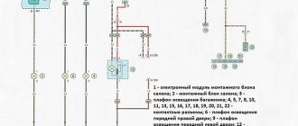
Electrical diagram of the block
Let's sum it up
Taking into account the above information, it becomes clear that the uninterrupted operation of the electric fuel pump of the VAZ 2110 or any other car will depend on correct and timely preventive maintenance, as well as on careful operation and compliance with certain rules.
Only clean fuel should be poured into the tank and the fuel filter should be changed promptly. It may also be necessary to periodically change or clean the fuel pump strainer, use a moisture displacer from the gas tank, etc.
Please note, it is not recommended to drive with an empty tank as the pump does not cool properly
Finally, we note that in the event of malfunctions in the operation of the internal combustion engine, it is quite possible to diagnose and replace the fuel pump with your own hands in a regular garage (if you have the tools)
However, working with the fuel system will require increased caution and compliance with all safety measures. If you are not confident in your abilities, it is better to contact experienced specialists
Where is the fuse for the fuel pump?
A common failure associated with the fuel system is that the fuel pump fuse blows. In this case, power is not supplied to the pump, and the fuel pump itself stops pumping gasoline into the main line. As a result, the car stalls, the pump does not buzz in the gas tank after turning the ignition key, and the engine does not start.
Why do fuel pump fuses blow?
A fuse is a small element whose task in the design of electrical circuits is to melt in the event of an overload. The device melts and the current-carrying circuit opens.
Using the example of a solution from the popular VAZ Priora model, we can superficially examine the design and operating principle of the fuse. The device is small, the outer casing is made of plexiglass.
There is a conductive element inside. Such an element is based on several plates, which are made of different materials. Between these plates there is a special low-melting material. Electricity passes through this material, which allows the fuse to be an integral part of the electrical power circuit of the fuel pump.
How to test a relay
If the electric fuel pump does not show any signs of life when the ignition is turned on, this does not mean that it has burned out. The cause of the malfunction may also be a relay. The easiest way to check the RB by ear is that when you turn on the ignition, the relay should click. If you don’t hear a click, there is a high probability that the “relay” is faulty.
But not everything is so simple - the problem can be “tricky”, for example, the car does not start the first time. The cause of the malfunction may be hidden in burnt relay contacts. It’s quite simple to check the functionality of the pump itself; proceed as follows:
- remove the protective casing, under which there is a block with relays and fuses;
- we unscrew the fastenings of the block, remove it, it remains attached to the wires;
- we pull the RB out of the block, place a jumper between two opposite contacts, thus directly supplying power to the BN;
- If, with such a connection, the electric motor of the pump begins to make noise, it means that the BN itself is working, most likely, the malfunction is hidden in the relay.
If there is no voltage on any of the contacts on the RB block, you should look for a break in the wiring; there may also be poor contact at the place where the wire is attached to the terminal.