Articles
- 2 Pinout of standard Euro connector
2.1 Upper power connector “A”
- 2.2 Bottom acoustic connector “B”
Pinout of ISO connectors for car radios
Not so often, but it still happens that almost every car owner is faced with the problem of do-it-yourself installation and subsequent independent connection of the head unit (car radio) to the standard acoustic circuit of his car. It would seem that this could be confusing, because everything is simple there! Yes, this statement is true. But, as experience shows, this confidence lasts until manipulations with the wires begin, during which the “handy” car owner begins to understand that he urgently needs pinout of Euro connectors for car radios, or even better, complete instructions for connecting the car radio.
Standards 1DIN and 2DIN
The differences between them are the height of the radios. The number 2 in the designation of the 2DIN standard indicates that the height of a double-DIN receiver is 2 times greater than a device made according to the 1DIN standard. The latest radios are now the most popular and widespread. Installation of double-din radios is not possible in every car, since an appropriate seat must be provided on the front panel.
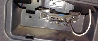
All car radios are divided into two types: with a proprietary connector, most often made in the form of a plug, and located on the rear wall, and with a universal ISO connector. In the first case, you should purchase a proprietary connector for the radio, the pinout of which matches the desired model. If the machine has an ISO socket, then the other end of the proprietary cable should also have an ISO plug. In the second case, the radio is connected directly to the ISO socket located in the car.
When replacing the radio with another one, you should look at the back wall and determine which block is located there. After this, you can decide whether to purchase a proprietary plug or you can connect the device to the machine through an already installed ISO socket. The pinout of the car radio connector is carried out according to the ISO 10487 standard.
If the car radio is without a plug
If the vehicle does not have ISO connectors for car radios, the car owner can install them himself. To do this, pinout is performed in the following order.
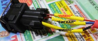
- If the plug is missing only in the car, you need to purchase an ISO connector from a specialized store. It must match the plug on the head unit that will subsequently be installed. If the plug is missing from the radio (in its place there is a bundle of wires), then you need to select a block.
- The first to be separated are the wires responsible for supplying voltage. Most often, they are distinguished by an increased cross-section and insulation in red and black colors. You can verify the correct choice using a test device.
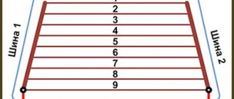
- Separate the wires for the speakers according to the car's electrical diagram. During the connection, it is prohibited to connect the negative wires to the common line or ground.
- Separate the wire necessary for the antenna to operate.
- After the linear outputs on the radio are designated, they are connected to the rods of the new connector. To do this, the bare ends of the wire are secured with a crimping tool. This technique ensures reliable fastening.
- After connection, you should check the functionality of the device.
ISO pinout
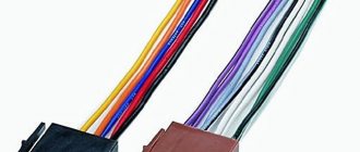
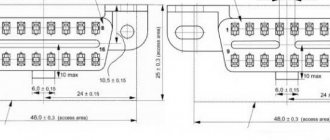
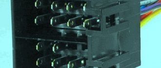
Many new radios increasingly use a Euro connector. It is a rectangular sixteen-pin plug consisting of one or two equal parts. An ISO plug is installed on the car, allowing you to connect any car radio that has the appropriate connector. The ISO pinout does not depend on the radio model equipped with such a connector.
Upper power connector A
It is used to supply current from the vehicle's on-board network, as well as to remove power from an active antenna or amplifier, to mute the sound and supply a backlight control signal. According to the standard, wires are marked by color:
- yellow - direct connection to the vehicle’s battery; it also supplies power to the receiver’s RAM, which provides storage of settings specified by the user;
- red - it supplies the main power;
- black is ground, the negative pole connected to the GU body;
- blue with a white stripe - when the car player is turned on, 12 V is supplied to the active antenna amplifier or the remote control controller of the car audio power amplifier;
- orange - a signal is sent to it from the vehicle’s side light switch to control the backlighting of the keys and display;
- brown - used to mute the sound, for example, while talking on the phone.
It is worth considering that two power supply systems are used. In the first case, the yellow and red wires on the pinout are connected together. The power supply to the radio does not depend on the position of the ignition key.
If you leave the car player on without a protection timer, the car battery may quickly drain.
The second system involves connecting the red wire through the ignition switch, and the yellow wire directly to the on-board network. Thanks to this, the power supply to the radio is connected to the position of the key. When the ignition is off, you can remove or insert the CD. It also keeps the audio system's built-in clock running and saves settings such as sound settings and radio channels.
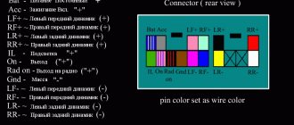
The pinout of the ISO connector of the radio, intended for power supply, is carried out as follows. Pins 1, 2 and 3 are reserved and are used by some head units to enable additional functions. Pin 4 is connected to the yellow wire, and pin 5 is connected to the blue/white wire. An orange wire is connected to pin 6. Pin 7 is connected to the red wire, and pin 8 is connected to the black wire. This connector is often painted brown.
Bottom speaker connector B
It is used to supply amplified sound from the car player to the speakers. The wires through which alternating current directly flows from the microcircuit are solidly colored, and the wires connected to ground have black stripes. Color marking is carried out as follows:
- the white wire connects to the left front speaker;
- the gray wire connects to the right front speaker;
- the green wire connects to the left rear speaker;
- The purple wire connects to the right rear speaker.
The pinout of the radio chip intended for connecting speakers is done as follows:
- purple wires connect to pins 1 and 2;
- gray - to pins 3 and 4;
- white - to pins 5 and 6;
- green - to pins 7 and 8.
Design of radio connectors and features of their installation
Pinout of ISO standard radio connectors
All car radio connectors have a fundamentally identical design - this is a block made of dielectric material (usually non-flammable plastic), in which metal contacts are installed, and a wiring harness is brought out on the reverse side. The shape and dimensions of the block, as well as the location of the contacts in it, depend on the standard.
The wiring harness for connecting the block to the parts of the radio, speaker systems and the car electrical system is made of wires in colored insulation, each of which has its own purpose. Most connectors, regardless of standard or manufacturer, use wires with the same color insulation to make connections for the same purpose. For example, the connection to ground is always made with a black wire, the right speakers are connected with gray and purple conductors, the left ones with green and white, +12/24 V power is supplied via the yellow wire, etc.
However, it should be borne in mind that the ISO standard does not define the purpose of the wires and contacts in the connectors, so many manufacturers use their own connection diagrams, in which the colors of the wires may not match those indicated above. Therefore, before installation, it is necessary to clarify the purpose of the conductors in the car.
As a rule, car radio connectors are sold with short-length mounting wires (15-30 cm) in polymer insulation, which, after stripping the ends, can be mounted to the corresponding terminals. The adapter connectors also have wires, but the connectors of different standards are located at both ends of the harness, so there is no need to strip the wires or perform other operations when installing them.
Pinout diagrams for radio tape recorders from popular manufacturers
Wiring of linear outputs on a standard radio can be done using two RCA connectors. This option is the most common, since power amplifiers have the same sockets. The pinout of connectors for Pioneer car radios contains from 10 to 20 contacts. Their purpose depends on the model of the multimedia device. For example, in the KEH series, the first pin is the antenna control, the second pin is the voltage from the ignition switch, etc. The speakers are connected to pins 3, 4, 5, 6, 8, 9, 10 and 11.
- Ford Focus 2 radio connector pinout
- Mystery radio pinout
- Connecting the radio directly
- How to connect your phone to the radio via bluetooth
Power connection
Connecting the power supply is the stage at which most mistakes are made when connecting the radio.
To obtain clean playback after installation, it is better to connect the black and yellow wires to the battery. Install an additional 10-20 A fuse on the yellow wire. The red wire is connected to the ignition circuit.
As a rule, the red and yellow wires are connected together, so the radio operates regardless of the ignition being turned off. But this option has a caveat - the radio will drain the battery, because will remain in sleep mode all the time after shutdown. To eliminate the possibility of the battery being discharged due to this nuance, a separate shutdown button is additionally placed on the red wire, thanks to which the power will turn off automatically when the car is parked for a long time.
Most people want to replace their stationary radio with a built-in one. This decision may be prompted by the fact that factory radios do not always produce the required number of watts or provide little power for the installed speakers.
Read more: Repair of car thresholds preparation and execution of work
The main rule when replacing stationary radios with built-in ones is the correct selection of adapters and related connectors.
Thus, the KY83190A radio, which is installed on Lifan cars, has its own plugs and is built into the standard 2Din slot already provided by the manufacturer. To use the KY83190A radio on other cars, special adapters for ISO standard plugs are required.
The manufacturer of the JVC brand radio has already made sure that the buyer, when purchasing his car radio, can install it himself. It comes with special studs for fixing the back and front for easy installation. JVC models are connected via an ISO connector.
For high-quality music sound, you need to move the fuse on the end side of the radio to the next socket, and connect the gearbox wire to the battery and insulate the reinforced concrete wire. It is also better to give preference to higher quality wires. Let's take a SONY brand radio as an example; most of them are also connected according to the standard scheme via an ISO connector, but it happens that some models have ISO connectors. They are individual, and you need to choose ISO adapters for them, or cut the wires and connect them to the connectors according to the diagram.
Of course, it is not recommended to cut the wires for connection, but if this happens, it is better to use heat-shrinkable tubes rather than electrical tape, since in winter it peels off, which can lead to a short circuit. In any case, connecting the car radio will become more convenient if it already has an ISO connector.
As for the Pioneer car radio, it also has ISO connection connectors. The connector for connecting the Pioneer radio has two plugs: black (from which the radio is powered) and brown (which produces acoustic output to the radio). When installing the Pioneer radio, you must correctly connect the red positive wire and use the battery fuse.
Thus, connecting the ISO connector of the radio greatly simplifies the work process.
Toyota
Adapter from the manufacturer Intro. Responsible for connecting the power supply and acoustic (sound) signal from the ISO connector to the standard radio socket for Japanese-made cars:
- Toyota;
- Lexus;
- Daihatsu.
Renault
ISO adapter from the manufacturer Intro for quickly connecting a modern multimedia system (MMS) or other non-standard device (radio tape recorder) to the place of the factory device. An adapter device of high quality at an affordable price, recommended for installation on cars of the following brands:
- Peugeot;
- Citroen;
- Renaults produced after 2005.
This technical adapter device is a plug for connecting to the standard connector of the player and the connector for the electrical wiring of the car. Without any special tools in a short period of time.
All you need to do is buy an ISO adapter
at an affordable price, and you can independently connect the car radio in the shortest possible time. At the same time, safety from incorrect connections, short circuits and other difficulties is guaranteed.
When you can't do without an ISO adapter
When purchasing a car with medium or higher equipment, the owner receives a standard car radio. Often its functions are limited to playing CDs, MP3 files, and listening to radio stations. The presence of a USB interface is much less common; only premium cars are equipped with a navigation system that allows you to display images from the rear view camera. Unfortunately, not everyone has the opportunity to buy a premium car; in other cases, the car radio is either completely simple or simply absent. The problem is solved by purchasing and installing one of the speaker systems offered on the modern market.
But here an additional difficulty arises - a warranty is provided for a new car, but it is preserved only if the owner adheres to all the rules for operating the vehicle. One of them is not to tamper with the car's electrical wiring. Therefore, many dealers prohibit installing radios and other equipment in third-party service centers. The problem is exacerbated by the fact that many car manufacturers use their own mounts, connectors and form factors, resulting in additional difficulties in installing the speaker system.
Methods for connecting a new radio
If the driver decides to replace the standard car radio, then he has two options:
- Cut off the “original” connectors and twist and solder the wires, and then insulate them. If, after solving the problem in this way, you contact the dealer to take advantage of the car’s warranty service, the probability of receiving a refusal will approach 100%. In addition, in the future it will be difficult to return everything to its original place. It is difficult to expect high quality from the resulting connection - when there is frost outside, the wires become tanned, and the twisting encounters vibration while driving, as a result of which the contact may disappear or periodically disappear.
- Select and purchase the appropriate ISO adapter
. This is the optimal solution to the problem - there is no need to make any changes to the car wiring, or damage the standard connectors. All that is required is to remove the plugs or the “original” car radio, and then install two adapters - for the antenna and for the electrics. This will take no more than 10 minutes! And if the driver has to go to a dealer’s service station, he can always return the standard radio.
The AvtoProfi store offers adapters for various car models. A wide range of adapters will allow everyone to choose the most suitable product that will facilitate the installation of a stereo system. And if you need additional help with choosing a product or making a payment, our employees will be happy to provide it.
A little theory: the pinout of the ISO connector of the radio is determined by the functionality of the contacts in the plugs, in accordance with their numbering. ISO radio connector is a connector for connecting a car's standard radio, certified according to international standards.
When trying to independently replace, for example, a car player from Pioneer with a JVC, car owners are faced with a situation where the wires in the plug are mixed up or do not even fit the shape of the connectors. In order to solve this issue, you need to buy an ISO plug, which is sold at any auto parts store. After that, pinout the head unit connector according to the diagram.